Audiovox 1286504A Скачать руководство пользователя страница 15

128-6504A

15 of 16

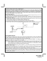
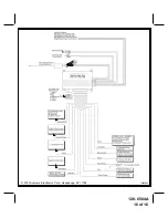
NOTE: A second 4002 series diode may be required to maintain the integrity of the hood open, shut down circuit.  If

this is the case, it must be installed as shown in the diagram above.  The anode (Non Striped) side must be
connected to the Gray/Black wire of the Remote Start Unit.  The cathode (Striped) side must be connected to
the hood pin switch.  If the hood pin switch is also used for an alarm trigger input, be certain to use the dual
diode assembly packaged with the Audiovox Remote Start Unit as shown in this installation guide.

AFTER THE CONNECTION OF THE NEUTRAL START SAFETY WIRE AS INDICATED IN ANY OF THE PREVIOUS
ALTERNATE CONFIGURATIONS, THIS CIRCUIT MUST BE TESTED FOR OPERATION.
Retest by following the steps outlined in the NEUTRAL START SAFETY TEST shown in this manual.

COMPLETING THE INSTALLATION:

After you have confirmed the operation of the Audiovox Remote Start unit and tested all the safety features of the
system:

1.  If you have not done so already, place the red rubber handle cover over the handle of the control switch for ease of

identification.  This will allow your customer to distinguish the Remote Start control switch from the program
switch.

2.  Mount the control module up and behind the dash securing it in place with cable ties or screws.  Be certain that the

chosen mounting location will not inhibit any of the controls of the vehicle.

3.  Securely harness and tie all wiring up and away from all hot and moving parts that they may come in contact with

under the dash board or in the engine compartment areas.

CAUTION: Particularly avoid the area around the steering shaft and column, as wires can wrap around these

mechanisms and impair the safe operation of the vehicle.

4.  Apply the Caution Labels supplied with this kit to a conspicuous area in the engine compartment.  Make sure to clean

the surface before affixing the label.

5.  Check the vehicle's wipers, lights, horn, etc.... to insure proper operation.

6.  Replace all panels that were removed during installation, and retest the system.

7.  Explain all activated features and safety systems associated with Remote Start Unit installed to the customer.

8. Place the Valet Switch Tag and or the Remote Start Control Switch Tag on their respective switches and

point these out to the customer.

15

Содержание 1286504A

Страница 1: ...In line Fuse Holders With Fuses 1 Control Switch 1 Programming Switch 1 Ring Terminal 4 1 2 Long Screws 1 Pin Switch 1 Remote Start Warning Label 1 Literature Package Model APS 55LRa Installation Man...

Страница 2: ...not penetrate any existing factory wiring or fluid lines Drill a 1 4 hole in the desired location and thread the hood pin switch into it using a 7 16 nut driver or deep well socket If using the mounti...

Страница 3: ...e wire as used by the battery 1 source Most vehicles have more than one battery source supplying power to the ignition switch Separate feed wires must be used for the Red and Red White wires If your v...

Страница 4: ...itch This wire will show 12 volts when the ignition key is turned to the to the ON or RUN and the START or CRANK positions and will have 0 volts when the key is turned to the OFF and ACCESSORY positio...

Страница 5: ...ition is in an upward or toward the driver direction GRAYWIRE NegativeInhibitInput1 Connect the GRAY wire to the previously mounted hood pin switch provided This wire will be routed through the firewa...

Страница 6: ...put when the ignition key is turned to the ON position and 0 Volts when the ignition key is OFF and when the vehicle is running under the control of the remote starter This wire should be connected to...

Страница 7: ...30 85 to a fused 12 volt battery source rated for a minimum of 25 Amp Connect terminal 87 to the third ignition wire in the vehicle C GM VATS Key Override If the vehicle has the General Motors VATS sy...

Страница 8: ...OUTPUT HARNESS The auxiliary 4 pin connector provides low current outputs to control various functions in the vehicle during different stages of the Remote Start unit s operation Understanding these...

Страница 9: ...es a ground pulse during the arming sequence or pulsed ground lock output Connect the Red wire to the low current ground signal wire from the factory door lock switch to the factory door lock relay Th...

Страница 10: ...y to the ON position 2 Press and release the program switch 3 times 3 Immediately turn the ignition key OFF then back to ON 4 Press and release the program switch 2 times 5 Use the Start button on the...

Страница 11: ...n coil s 1 For vehicles utilizing independent coils per cylinder connect the three Green Black leads to alternate coils To achieve optimum performance the coil signals must be evenly distributed This...

Страница 12: ...wire be connected to the ignition switch side of the Neutral Start Switch Consideration for the placement of a starter inhibit relay is important as well and should be connected to the ignition switc...

Страница 13: ...ble switch 4 Connect the other side of the enable switch to the Black White enable input wire of the Remote Start unit The reference diagram below shows a typical GM B Body ECM reference wire and how...

Страница 14: ...ire Gray Black using a 4002 series diode as shown above 14 These situations should be carefully considered before altering the vehicle s wiring and must be fully explained to the consumer Circuits may...

Страница 15: ...the control switch for ease of identification This will allow your customer to distinguish the Remote Start control switch from the program switch 2 Mount the control module up and behind the dash sec...

Страница 16: ...128 6504A 16 of 16 2003 Audiovox Electronics Corp Hauppauge NY 11788 1286504A...

Отзывы: