


TRIGGER
IN OUT
_
+
BUS 1
TREB
ON
TRIGGER
AUT
O
BUS 2
TREB
BUS 1
BASS
BUS 2
BASS
BUS 1
LEVEL
BUS 2
LEVEL
+
+ -
-
BUS 1
OPTICAL
PCM AUDIO
ONLY
1
1
2
2
BUS
INPUT
LEFT RIGHT
FUSE: T12AL 250VAC FOR 120VAC 60HZ
FUSE: T6.3AL 250VAC FOR 230VAC 50HZ
POWER
RATING:
_
+
_
+
BR
ST
L R
LINE IN LINE IN
SPEAKER SPEAKER
_
+
BRIDGE
1 2 LINE IN 1 2 LINE IN
ZONE 5
VOL
VOL
_
+
_
+
BR
ST
L R
LINE IN LINE IN
SPEAKER SPEAKER
_
+
BRIDGE
1 2 LINE IN 1 2 LINE IN
ZONE 6
VOL
VOL
_
+
_
+
BR
ST
L R
LINE IN LINE IN
SPEAKER SPEAKER
_
+
BRIDGE
ZONE 3
VOL
VOL
_
+
_
+
BR
ST
L R
LINE IN LINE IN
SPEAKER SPEAKER
_
+
BRIDGE
1 2 LINE IN 1 2 LINE IN
ZONE 4
VOL
VOL
1 2 LINE IN 1 2 LINE IN
_
+
_
+
VOL
BR
ST
L R
LINE IN LINE IN
SPEAKER SPEAKER
BUS BUS
BUS BUS
BUS BUS
BUS BUS
BUS BUS
BUS BUS
1 2 LINE IN 1 2 LINE IN
_
+
BRIDGE
VOL
ZONE 1
_
+
_
+
BR
ST
L R
LINE IN LINE IN
SPEAKER SPEAKER
_
+
BRIDGE
1 2 LINE IN 1 2 LINE IN
ZONE 2
VOL
VOL
~120V60Hz/230V50Hz 1000W
3076079
3-30V 12
SMALLEST MAX
20MA
1.0A
AD5012
OWNER’S MANUAL
13970 SW 72nd Ave, Portland, OR 97223 • 503.914.4688 • www.audiosource.net
3
1.
2.
FRONT PANEL CONTROLS
4.
5.
6.
8.
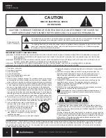
REAR PANEL CONTROLS
Figure 1. Front Panel
3.
9.
10.
11.
Figure 2. Rear Panel
Master Power Switch / Indicator LED
Front panel pushbutton power switch tur
QVWKHDPSOL¿HURQDQGRII
. When the
s
ZLWFKLVRQDQGWKHLQGLFDWRU/('LVUHGWKHDPSOL¿HULVLQVWDQG
by mode. When
the LED is blue
WKHDPSOL¿HULVIXOO\DFWL
ve. The master power switch will tur
QRII
WKHDPSOL¿HUQRPDWWHUZKLFKS
ower mode has been selected with the rear panel
Power Mode switch.
Zone Status Indicators
Each pair o
I
channels or zones has a bi-color LED to indicate its operational
status. These indicators provide quick and easy troubleshooting o
I
the system. I
I
the
circuitry determines that a channel must be shut down due to excessive heat or low
impedance (a short), only the channels that are a
II
ected will be turned o
II
causing
the zone LED to turn red. The remaining zones will continue to operate and maintain
a blue LED status. Once the condition has been corrected
I
or the zone in question,
the status LED will return to blue.
Note:
When the power LED is red and the zone status LEDS are not lit (o
II
) indicates
the unit is in stand by mode.
Bus Line Inputs / Outputs
The AD5012 has two common or Bus inputs that receiv
HVDXGLRVLJQDOVIURP
standard line-level audio sources and sends them to any or all channels. The Bus
line outputs are direct
I
eed-through to allow the Bus inputs to be
I
ed to other
DPSOL¿HU
s. Be sure to use high quality RCA cables that
I
eature low impedance,
shielding and high quality connectors.
Power Mode Switch
This switch selects the turn-on stimuli that will put the ampl
LILHULQUHDG\PRGH
“Trigger” setting relies on 3-30Vdc voltage
going
into
the
trigger
input
to
activate the
DPSOL¿H
r. “Auto” setting senses a signal on the RCA line-level inputs
and automatically puts the amp in ready mode. “On” setting puts the amp
constantly in ready mode so that it can be controlled by the master power switch
on the
IURQW
panel.
,Q³$XWR´PRGHWKHDPSOLILHUZLOOWDNHDSSUR[LPDWHO\
PLQXWHVWRUHWXUQIURPUHDG\WRVWDQGE\PRGH
Trigger Input / Output
The trigger input is a handy
I
eature when connecting
WKHDPSOLILHUWRDQ
automated audio system. The 3.5mm mini plug jack will accept a 3-30Vdc, 20mA
output
IURP
another device, or
IURP
a separate power supply. When the trigger
input is energized, the amp turns
I
rom standby to ON mode. When using the
AD5012 with a receiver without a trigger output, the voltage can come
IURP
a 12V
wall wart (3.5mm tip-positive connector) plugged into the receiver’s switched outlet
and the trigger input. The A5012 can also provide an output trigger voltage (12Vdc,
1.0A)
to
turn
on and
RII
other
devices
in the audio
system .
When
WKHDPSOLILHU
WXUQVRIIVWDQGE\PRGHWKHYROWDJHZLOOGURSWR]HUR
Optical Input
7KLVLQSXWXVHVDILEHURSWLFFDEOHWRWUDQVPLWDGLJLWDOVLJQDOWRWKHDPSOLILH
r.Use
RIWKLVLQSXWLVUHFRPPHQGHGIRUDGYDQFHGXVHUVZKRDUHIDPLOLD
r with the
audio source’s OSD system. When using the Optical input, make sure the
source unit the cable is plugged into is in
Digital PCM (2 Channel) Mode
.
3OHDVHUHIHUWR\RXUVRXUFH
’s operating manual when using this input.
NOTE:
Optical Input will not decode 5.1 or 7.1 signals; only Digital PCM signals.
Bus Level Controls
Each Bus has its own independent level adjustment. This allows the output level
RIHDFK%XVWREHDGMXVWHGWRPDNHXSIRUGLIIHUHQWVRXUFHOHYHOVRUWRJURXS
GLIIHUHQWVRXUFH¶VYROXPHOHYHOV
. These controls are rotary encoders, with 1dB
“click” increments. The remote control can also increase or decrease these levels
independently.
7.
12.
AD5012
DIGITAL
MULTI-ZONE POWER AMPLIFIER
1
2
3
4
5
6
7
8
Bus 1 and Bus 2 Bass and Treble Controls
7KHVHFRQWUROVFDQDGMXVWEDVVDQGWUHEOHIUHTXHQFLHVG%
at 100Hz
and 10kHz on Bus 1 and Bus 2 independently.
Bridging Switch
%\VLPSO\IOLSSLQJDVLQJOHVZLWFKWZRFKDQQHOVFDQEHFRPELQH
d to increase the
WRWDOSRZHURXWSXW7KLVLVKHOSIXOZKHQ
extra power is needed in certain areas.
Note:
The minimum impedance
I
or bridged channels is 8 ohms. Also, please
observe the proper speaker wiring when bridging channels. Input selection and
volume settings
I
or bridged channels will be controlled by the le
I
t channel. “BR” is
bridged mode and “ST” is non-bridged or stereo mode.
Channel Gain Control
Each channel has its own independent level adjustment. This allows the output
lev
HORIHDFKVSHD
ker to be per
I
ectly matched to its area. It can also be used to
limit the maximum audio level in a certain area.
Input Selection Switch
Each channel is capab
OHRIGHOL
ver
LQJWKHVRXUFHIURPRQHRIWKUHHLQSXW
s. The
three main inputs are Bus 1, Bus 2 and LINE IN. The selection
I
or these inputs
is done via the Input Selection switch associated with each channel. Select the
desired source input. Set the Input Selection switch to Bus 1 (will play source
connected to the Bus 1 input), Bus 2 (will play source connected to the Bus 2
input) or LINE IN (will play source connected to that channel’s LINE IN).
Individual Channel Input
All twelve channels have their own dedicated input that allo
ZVWKHFRQQHFWLRQRI
audio sources in addition to the common Bus inputs.
7KLVLVXVHIXOZKHQXVLQJ
the AD5012 with an audio matrix switcher.
Speaker Output Terminals
The AD5012 uses high quality Phoenix style connectors
I
or the speaker
connections. Use 14-18 gauge stranded two-conductor loudspeaker wire.
(QVXUHWKDWDWOHDVWLQFKHVRIHDFKFRQGXFWRUDUHVHSD
rated. Strip away ¼
LQFKRILQVXODWLRQIURPHDFKFRQGXFWR
r. Connect the appropriate conductor
to each screw terminal, observing correct polarity. Also, please observe proper
speaker wiring when bridging channels.
9
10 11 12
13
13.
14
15


