background image

Receiver Installation

3

Location

For best operation the receiver should be at least 3' (1 m)
above the ground and at least 3' (1 m) away from a wall or
metal surface to minimize reflections. Keep the receiver 
antennas away from noise sources such as digital equipment,
motors, automobiles and neon lights, as well as away from
large metal objects. In multi-channel systems, position
receivers at least 3' (1 m) apart and keep operating 
transmitters at least 6' (2 m) from the receivers to help assure
maximum RF performance.

Output Connection

The receiver provides unbalanced, aux-level output from a 

1

/

4

"

TS (“mono”) phone jack; an output cable is not included. Use 
a shielded audio cable with 

1

/

4

" phone plug to connect the

receiver’s AF Out jack to the mixer/amplifier’s aux-level input.

Power Connection

Connect the DC plug on the included AC power adapter to the
DC power input on the back of the receiver. Secure the cord
over the cord hook on the back of the receiver, to keep the
plug from being detached by an accidental tug on the cord.
Then plug the adapter into a standard 120 Volt 60 Hz AC
power outlet. 

(Note that the receiver has no power Off/On switch. The
receiver will be energized whenever the power adapter is 
connected and plugged into the AC outlet. Unplug the power
supply from the AC outlet when the system is not in use –
both for safety, and to conserve energy.)

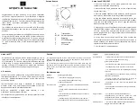
Front Panel Controls and Functions (Fig. B)

1.

ANTENNAS:  Position the “signal” antenna (1a) and 
“ground” antenna (1b) as shown in Figure A.

2.

POWER INDICATOR:  Lights when power is supplied to 
the receiver.

3.

RF INDICATOR:  Lights to show presence of transmitter 
signal.

4.

AF PEAK INDICATOR:  Only lights when audio distortion 
is present at maximum modulation. Not affected by 
position of Volume control.

Antennas

A novel “dipole” antenna system on the receiver improves
operation by providing a “ground” element in addition to the
usual “signal” element. Position the two antennas at 90° in the
form of a “V,” or position the left (“signal”) antenna vertically
and the right (“ground”) antenna horizontally, in the shape of 
an “L” (Fig. A). Use the position that performs better in your
operating environment. Be certain to extend both antennas to
their full 15" (38 cm) length by holding them at their bases and
pulling out on their caps. Both antenna elements may be
swiveled to the left and right, but do not attempt to rotate
them in a screwing/unscrewing motion. To do so may damage
the antenna and/or receiver. For best performance, locate the
receiver so its antennas are in direct line-of-sight to the 
transmitter's likely operating position.

Receiver Controls and Functions

Rear Panel Controls and Functions (Fig. C)

5.

AUDIO OUTPUT JACK: 

1

/

4

" TS (Tip-Sleeve) or “mono” 

phone jack. Use a shielded cable to connect to an 
unbalanced aux-level input of a mixer or amplifier.

6.

VOLUME CONTROL:  Adjusts the audio level at the 

1

/

4

"

output jack. Does not affect AF Peak indicator.

7.

CORD HOOK: Loop the cord around the cord hook to keep 
the DC plug from pulling out accidentally.

8.

POWER INPUT JACK: Connect the DC plug from the 
included AC adapter.  


Содержание Freeway ATW-251

Страница 1: ...rofessional VHF Wireless Systems ATW 251 UniPak System ATW 251 G Guitar System ATW 251 H Headworn Microphone System ATW 251 L Lavalier Microphone System ATW 252 Handheld Microphone System Installation and Operation ...

Страница 2: ...cW headworn microphone H or a lavalier mic L for particular applications All A T Wireless Essentials microphones and cables available separately are pre terminated for use with any ATW 251 system Because 200 Series packaging is designed to hold all versions of the system some compartments in the carton are intentionally left empty The ATW R250 receiver includes a space saving switching power suppl...

Страница 3: ...the signal antenna 1a and ground antenna 1b as shown in Figure A 2 POWER INDICATOR Lights when power is supplied to the receiver 3 RF INDICATOR Lights to show presence of transmitter signal 4 AF PEAK INDICATOR Only lights when audio distortion is present at maximum modulation Not affected by position of Volume control Antennas A novel dipole antenna system on the receiver improves operation by pro...

Страница 4: ...light strongly with a fresh battery As the battery weakens the indicator will grow dimmer When the indicator becomes very dim or goes out there is little life left in the battery Replace it at once for continued operation of the transmitter All transmitters feature battery save switches Fig D F As supplied the switch is set in the High position for maximum range Switching to the Low position incre...

Страница 5: ...ier Input Level Adjustment Input trimmer controls in the transmitters enable you to maximize performance for a particular microphone or guitar sensitivity or to adjust for different acoustic input levels Adjusting Input Level UniPak Transmitter Slide the battery cover off the top part of transmitter and remove the screwdriver from its clip Fig D Gently turn both the MT Mic Trimmer and GT Guitar Tr...

Страница 6: ...icrophone operations are unprotected from interference from other licensed operations within the band If any interference is received by any Government or non Government operation the wireless microphone must cease operation If you need assistance with operation or frequency selection please contact your dealer or the A T professional division Extensive wireless information also is available on th...

Страница 7: ...unt adapter kit mounts one ATW R250 in a single 19 rack space ATW RMS1 Remote mute switch designed to be installed between a wireless microphone using an HRS type connector and its associated body pack wireless transmitter Includes permanently attached 22 cable and belt clip ATW RCS1 Remote momentary mute cough switch designed to be installed between a wireless microphone using an HRS type connect...

Страница 8: ...Figure A p 3 Antennas Figure B Front panel controls and functions Receiver Controls and Functions Figure C Rear panel controls and functions 2 3 4 8 1a 1b 6 5 8 7 ...

Страница 9: ...ve Switch under screwdriver clip Guitar Trimmer GT Microphone Trimmer MT Battery Polarity Diagram Battery Save Switch BATT ON OFF ST BY INPUT POWER BATT ANT OFF ON ST Battery Condition Indicator Power Switch On Standby Off Battery Condition Indicator Input Connector Power Switch Off Standby On Antenna Screwdriver Gain Trimmer ...

Страница 10: ...U S is required for return This warranty excludes defects due to normal wear abuse shipping damage or failure to use product in accordance with the instructions This warranty is void in the event of unauthorized repair or modification or removal or defacing of the product labeling For return approval and shipping information contact the Service Dept Audio Technica U S Inc 1221 Commerce Drive Stow ...

Отзывы: