Turn down the mixer/amplifier level before starting up the
wireless system.
Switch on the receiver. Do
not
switch on the transmitter yet.
Receiver On…
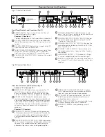
The Channel Designator Displays will light. If any of the RF
LEDs light up at this point, there may be RF interference in the
area. If this occurs, select another frequency using the front-
panel channel selectors. While holding in the “Set” button,
press the “Up” or “Down” button to access the desired
frequency; then release the Set button to select the channel.
Transmitter On…
Refer to the manual included with each Engineered Sound
transmitter for details of setup and operation.
Before turning on the transmitter,
make certain it is set to the
same operating channel as the receiver.
When the transmit-
ter is switched on and in normal operation, the
receiver’s RF signal level indicators will light up from left to
right. For optimum performance at least four, and preferably
five, of the signal strength indicators should light up when the
transmitter is switched on. One of the Tuner LEDs (A or B)
also will light up when the transmitter is on, indicating that its
signal has been received and the receiver’s Tone Lock squelch
circuit has opened.
Setting Levels
Although Engineered Sound receivers require no level
adjustment, correct adjustment of transmitter audio input
and mixer/amplifier input and output levels is important for
optimum system performance.
Engineered Sound transmitters include adjustments for
optimum audio modulation levels. Refer to the transmitter’s
manual for full details. Maximum audio input to the mic or
guitar should light about three or four green LEDs on the
receiver’s AF Level indicator. Audio modulation from the
transmitter level should not be allowed to light the red LED –
doing so will cause the system to overload and distort.
The audio output level of the ESW-R220 has been optimized
for best performance and no adjustment is necessary. The
level control on the front panel controls the headphone jack
only.
Receiver Squelch
The sophisticated Tone Lock
™
system in ES wireless units
eliminates the need for any user-adjustable squelch control on
the receiver. Do not attempt to open the receiver housing or
adjust any internal alignment controls.
RF Interference
Please note that wireless frequencies are shared with other
radio services. According to Federal Communications
Commission regulations, “Wireless microphone operations are
unprotected from interference from other licensed operations
in the band. If any interference is received by any Government
or non-Government operation, the wireless microphone must
cease operation...”
If you need assistance with operation or frequency selection,
please contact your dealer or the Audio-Technica professional
division. Extensive wireless information also is available on the
Audio-Technica Web site at www.audio-technica.com.
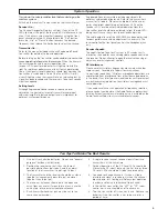
5
System Operation
Ten Tips To Obtain The Best Results
1. Use only fresh alkaline batteries. Do not use “general
purpose” (carbon-zinc) batteries.
2. Position the receiver so that it has the fewest
possible obstructions between it and the normal
location of the transmitter. Line-of-sight is best.
3. The transmitter and the receiver should be as close
together as conveniently possible, but no closer
together than three feet.
4. The receiver antennas should be in the open and
away from any metal. If mounted in a rack, have the
unit on top, or use external/remote antennas.
5. Each transmitter/receiver pair must be set to the
same channel number.
6. A single receiver cannot receive signals from two
transmitters at the same time.
7. For best operation, all the RF Level LEDs should be
lit (maximize RF input); but only the first two or three
AF Level LEDs should be lit (don’t overmodulate).
8. You need to change channels 1) when a strong
interference signal is received, 2) when the channel
breaks down, or 3) during multiple-system operation
in order to select an interference-free channel.
9. In the UniPak transmitter, the “MT” or “GT” input
control not in use should be set to minimum.
10. Turn the transmitter off when not in use. Remove the
batteries if the transmitter is not to be used for a
period of time.

