Audio Technica AEW-4110 Скачать руководство пользователя страница 23

System Operation

Artist Elite wireless receivers and transmitters are extremely
versatile components with many operating features and 
functions, some of which are not obvious. As a result, we 
suggest the following approaches to assure a “comfort level”
with any new equipment:

1. Begin using a single receiver/transmitter pair at their Default 

(“

DEF

”) settings, to become familiar with equipment 

functions and operation before doing any customizing. 
(If the Default frequency is not usable in your area, change 
the frequency to one that is suitable.)

2. Before installing/starting up a large multi-channel system, 

explore the functions and operation of only two or three 
receiver/transmitter pairs together.

Basic Operation – Single AEW-R4100 receiver system:

Turn down the AF Level of the mixer or amplifier. Switch on the
receiver. Do 

not

switch on the transmitter yet.

Turning on the Receiver

The Alert indicator and the LCD window lights up; the normal
operation LCD display appears after 1–2 seconds. If any of the
bars show in the “

RF

” bar-graph meters, there may be RF 

interference in the area. If this occurs, select another frequency
as explained below. (If the Meter Hold function has been 
selected, one of the RF bars in each column will be flashing,
indicating the lowest RF levels received.)

Selecting/Setting Receiver Frequency

Selection of the desired operating frequency is made through
the function menus. There must be no local interference on that
frequency. If the Default frequency (lowest in band) happens not
to be usable, the receiver frequency may be set manually, or by
using the IntelliScan function.

• Manual frequency selection:

Adjust the receiver frequency 

as detailed in the next section.

• IntelliScan frequency selection:

The receiver’s IntelliScan 

function may be employed to select a usable operating 
frequency automatically, as detailed in the section following 
on page 25.

Note: Once the receiver frequency is set, the associated 

transmitter

must be set manually to the receiver’s 

exact

frequency. See page 26 for the correct procedure.

Setting Receiver Frequency Manually

1.

Touch

the Mode/Set button once. “FRQ” appears on the first

line of the LCD window with the current frequency setting on
the second line. (The receiver is now in Menu mode.)

2.

Touch

the Mode/Set button again. The small flashing word 

“EDIT” appears at the bottom of the window. (The receiver 
is now in Edit mode.)

3. Use the Up/Down arrow buttons to change the frequency. 

Touch

either arrow for single steps, or 

hold

either arrow for 

rapid cycling through the band. Frequencies “wrap around”
to the other end of the range when the top or bottom of the 
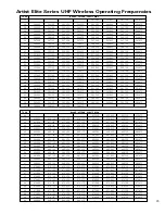
band is reached. Choose a frequency appropriate for your 
area, avoiding frequencies with active TV channels. (See the 
frequency listings on pages 29 and 30.)

Note: The top line of the LCD indicates when frequencies
belong to IntelliScan groups. Asterisks (*) are displayed in front
of “FRQ” to indicate membership in one of more of the three
groups (Figure R on page 25). See page 30 for frequency group
listings.

4. To choose this frequency, 

hold

the Mode/Set button until the 

word “STORED” appears in the receiver’s window. (If you do 
not wish to complete this selection, 

touch

the Mode/Set 

button 

once

. The word “ESCAPE” appears briefly in the 

window, and the receiver returns to Menu mode.)

5. When finished entering a frequency, 

touch

the Up arrow 

button 

once

. The display reads “QUIT.” 

There are several ways to quit, depending on whether the 
current Name is to be retained or the frequency stored to a 
user preset. See page 14 for help with Quitting and saving 
changes. 

To quickly store the new frequency into the “NAME?” 
location, 

touch

the Mode/Set button. The receiver shows 

“NAME?” in the top line and the new frequency in the 
bottom line. 

Note: You must now set the transmitter to the exact same
frequency for the system to operate!

24

The details of setting up and operating a multi-channel 
system vary greatly in complexity, depending upon the 
number of receivers and nature of the system. Because the
feature-rich nature of AEW units can greatly increase this
complexity, we suggest starting with a simpler, straightfor-
ward setup and use to become familiar with the 
equipment and its capabilities.

Single AEW-R4100 receiver system:

Begin using a receiver and transmitter at their Default 
(“

DEF

”) settings, to become familiar with equipment 

functions and operation before doing any customizing.
(If the Default frequency is not usable in your area, 
manually change only the frequency to one that is 
suitable.)

Single AEW-R5200 receiver system (two channels):

Start out using only Channel 1, treating this the same as 
the single AEW-R4100 above.

Multiple-receiver system with link cables only:

The link cables provide data and control between 
receivers. The IntelliScan

feature scans for clear channels 

and assigns non-conflicting frequencies to all linked 
receivers. (If IntelliScan is not used, the receiver 
frequencies may all be set individually/manually, as with 
any standard receiver, selecting frequencies that are 
within the same IntelliScan groups listed on page 30.)

Multiple-receiver system with Ethernet-connected 
computer interface:

Refer to the separate AEW Control Interface manual for 
setup and operation of a computer-based system. Basic 
hardware aspects of the receivers, and all transmitter 
setup/operating information, are in the manual you are 
now reading.

Touch:

A momentary press of the Mode/Set button. It is 

used to enter Menu mode, to enter Edit mode, or to Escape 
without making any changes to current settings.

Hold:

A press and hold (about two seconds) of the Mode/Set

button. It is used to accept a new setting when the receiver 
is in Edit mode or to save the current settings to one of the 
five user-defined name presets or the internal memory 
location (“NAME?”). 

Содержание AEW-4110

Страница 1: ...4000 5000 Series Professional UHF Wireless Systems Installation and Operation ...

Страница 2: ...ubject to the following conditions 1 This device may not cause harmful interference and 2 this device must accept any interference received including interference which may cause undesired operation AVIS RISQUE DE CHOC ÉLECTRIQUE NE PAS OUVRIR CAUTION RISK OF ELECTRIC SHOCK DO NOT OPEN Warning To prevent fire or shock hazard do not expose this appliance to rain or moisture Attention Pour prévenir ...

Страница 3: ... 12 AEW R4100 Rear Panel Controls and Functions 13 Common Receiver Controls 14 Power On Off 14 Level Alert Light LED 14 LCD Window 14 Mode Set Button 14 Up Down Arrow Buttons 14 Changing Receiver Settings 14 Menu Mode 14 Edit Mode 14 Quitting and Saving Changes 14 Receiver Controls and Functions 15 IntelliScan Channel Assignment System 15 Receiver Locks 15 Antenna Power 15 Digital Tone Lock Squelc...

Страница 4: ...ss Operating Frequencies Groups 29 Serial Number Log 31 Warranty Statement 32 Guide to Illustrations 5 Receiver Location Figure A 8 Connecting Linked Receivers Figure B 9 AEW R5200 Front Panel Controls and Functions Figure C 10 AEW R5200 Rear Panel Controls and Functions Figure D 11 AEW R4100 Front Panel Controls and Functions Figure E 12 AEW R4100 Rear Panel Controls and Functions Figure F 13 Rec...

Страница 5: ...ign and manufacturing experience Recent advances in the quality and sophistication of profession al live sound systems have been nothing short of revolutionary Tours clubs broadcast events corporate facilities and worship venues sound better than ever utilizing better system design and better components in the audio chain That s why Audio Technica has been partnering with industry professionals on...

Страница 6: ...turers All Artist Elite Series components feature soft touch controls for quick easy access to a formidable range of functions an LCD information display in each unit provides convenient visual indication of unit settings and operation Digital data sent by the transmitters is available for display on the receivers Receivers Both Artist Elite receiver models feature True Diversity reception Two ant...

Страница 7: ...r geographic area Also only certain of the available operating frequencies may be used together Operating frequencies and IntelliScan frequency groupings will be found on pages 29 30 Use of the IntelliScan channel assignment system will determine and set appropriate frequencies automatically Receiver Installation Location For best operation the receiver should be at least 3 ft 1 m above the ground...

Страница 8: ...ons of AEW R4100 and AEW R5200 receivers The exclusive IntelliScan channel assignment system provides easy automatic scanning of the RF spectrum and assignment of usable compatible frequencies to all linked AEW receiver channels Both AEW receiver models can be interconnected using Link In Out jacks and included link cables In addition the AEW R5200 offers a built in Ethernet 10 BaseT connection wi...

Страница 9: ...perating frequency and edit receiver function choices 8 12 MODE SET BUTTON Use in conjunction with the Up Down arrow buttons to step through menus choose operating frequency and select receiver function options 13 FRONT MOUNT ANTENNAS Cables and panel connectors are included with the AEW R5200 to permit attaching antennas at the front panel Front Panel Controls and Functions Fig C 1 POWER SWITCH P...

Страница 10: ...his output is transformer isolated from the 1 4 TRS Instrument output jack 19 26 GROUND LIFT SWITCH Disconnects the ground of both the Mic and Instrument output jacks on the associated receiver channel Normally the switch should be to the right ground connected If hum caused by a ground loop occurs slide switch to the left ground lifted 20 NETWORK INTERFACE CONNECTOR An Ethernet connection on the ...

Страница 11: ...SWITCH Press Power switch in and the receiver readouts will light 33 HEADPHONE OUTPUT 1 4 6 3 mm TRS stereo phone jack Plug in either a mono or stereo headphone to monitor receiver signal 34 HEADPHONE LEVEL CONTROL Adjusts the level of the headphone jack only it does not affect receiver audio output 35 ALERT INDICATOR The Alert Indicator lights a When the receiver is in the Mute mode b When no RF ...

Страница 12: ...48 AC POWER INPUT IEC type connector for 100V 240V AC 50 60 Hz power input No adjustment for mains voltage frequency is necessary Receiver Controls and Functions Continued 41 40 RX NAME RX LOCK TX LO TX HI TX LOCK TX NAME Figure G Receiver LCD Window 49 51 53 58 59 52 57 54 50 56 55 49 RF SIGNAL LEVEL INDICATOR Shows the strength of the RF signal received from the transmitter Also indicates which ...

Страница 13: ...mode touch the Mode Set button The top line of the receiver display shows FRQ preceded by one two or three asterisks Touch the Up Down arrow buttons to scroll through the available functions that may be changed See the chart on page 17 for a list of functions and display indication Note that the display s lower line indicates the current setting for a given function Enter Edit mode When the functi...

Страница 14: ...e edited from the receiver s front panel or from an associated computer via an Ethernet connection to a linked AEW R5200 ALL LOC Receiver functions and frequency settings cannot be edited from the front panel or from a computer via an Ethernet connection to a linked AEW R5200 ALL LOC must be changed via the receiver s Menu before other settings can be changed PC LOC Receiver functions and frequenc...

Страница 15: ...Touch the Mode Set button once LOAD or STORE appears in the LCD 4 Touch the Up or Down arrow once if needed to change the selection to STORE 5 Hold the Mode Set button until PRSET1 or the name of the currently loaded Preset appears on the second line of the LCD 6 If desired touch the Up or Down arrow to cycle through the available choices PRSET1 through PRSET5 or their previously changed names 7 A...

Страница 16: ...tion to LOAD 5 Hold the Mode Set button The name of the currently loaded Preset appears on the second line of the LCD 6 Touch the Up or Down arrow to cycle through the available choices stopping on the desired choice 7 Hold the Mode Set button until LOADED appears briefly in the LCD The receiver reverts to normal operation with the selected preset s functions loaded The top display line indicates ...

Страница 17: ... is designed for greatest contrast and best viewing with the window rotated somewhat away from the viewer about 30 degrees not straight on for a more convenient holding viewing position Power Mute Button The transmitters have a combination Power and Mute switch Figure J K When used in combination with the programmed choices explained below the various functions available to the transmitter user ma...

Страница 18: ...atch the receiver s AF meter 6 indication and the Alert light to make certain they are not triggered often by the highest audio levels The transmitter s red LED power indicator which is on during normal operation will blink off if the peak audio input reaches overload level Power Mute Locks Programmable Power Mute Locks limit the functioning of the Power Mute button as desired for particular users...

Страница 19: ... touch the Up or Down arrow to cycle through the available choices PRSET1 through PRSET5 or their previously changed names 7 Accept or enter a name for the Preset a To accept the standard name PRSET1 PRSET5 or the previously stored name for a new Preset configuration and to update overwrite any previously stored configuration choices a1 At the desired Preset hold the Set button until the first cha...

Страница 20: ...and D 655 500 MHz Table 2 UniPak Transmitter Functions Transmitter Controls and Functions Continued 21 Handheld Transmitter Functions Function Menu Default Value Choices Edit Wrap around Frequency Lowest in band 200 discrete frequencies Yes RF Power RF LOW RF LOW RF HI Yes Audio Input Level Dynamic 6 dB 6 dB 0 dB 6 dB 12dB No Condenser 6 dB 0 dB 6 dB 12dB No Power Mute Locks NO LOC NO LOC ALL LOC ...

Страница 21: ...lkaline batteries Figure Q Insert the first battery and slide it down Then insert the second battery bottom first into the space remaining Make certain the batteries are fully seated in the battery compartment 3 Slide the lower body cover back up the body then screw the housing together Do not overtighten Note Remove batteries from the handheld transmitter starting at the bottom end of the top bat...

Страница 22: ...ically but may not have the operating range of the wire antenna The wire antenna should hang down at its full length from the bottom of the transmitter If the received signal is marginal experiment with different transmitter positions on your body or instrument try the wire antenna or try repositioning the receiver Do not attempt to modify either transmitting antenna Replace them only with the sam...

Страница 23: ...top line of the LCD indicates when frequencies belong to IntelliScan groups Asterisks are displayed in front of FRQ to indicate membership in one of more of the three groups Figure R on page 25 See page 30 for frequency group listings 4 To choose this frequency hold the Mode Set button until the word STORED appears in the receiver s window If you do not wish to complete this selection touch the Mo...

Страница 24: ...tions on page 9 2 Switch on all the slave receivers first switch on the Master receiver last Alternatively all receivers can be turned on simultaneously as when using AC power plug strips controlled by a single AC switch If an AC power or link connection is interrupted even briefly all receivers must be turned off and the power up sequence repeated to assure complete system control 3 Using control...

Страница 25: ...e audio input level to the transmitter for best modulation and highest signal to noise ratio with minimum distortion Select the highest setting that does not result in over modulation with the highest audio instrument input levels an AF indication on the receiver no higher than 3 watch the receiver s AF bar graph 6 indication and the Alert light to make certain that they are not triggered by the h...

Страница 26: ...x 1 74 44 0 mm H x 9 26 235 0 mm D AEW R5200 18 98 482 0 mm W x 1 74 44 0 mm H x 10 85 275 5 mm D Net Weight without accessories AEW R4100 3 8 lbs 1 7 kg AEW R5200 8 8 lbs 4 0 kg Accessories Included Both receivers Detachable IEC type AC power cable two flexible UHF half wave antennas link cable AEW R4100 Rack mount adapters AEW R5200 IEC type AC pass through cable front mount antenna cables and c...

Страница 27: ...tachable IEC power cable IEC pass through cable ten RF cables front mount antenna cables and connectors four DC power cables to power up to four 3000 Series receivers Mounts in a single 19 rack space AEW DA660D Same as AEW DA550C except 655 680 MHz operation AT8628a Joining plate kit allows rack mounting two AEW R4100 receivers side by side in a single 1U 19 rack space ATW A20 Pair of UHF ground p...

Страница 28: ... 375 565 500 565 625 565 750 565 875 30 566 000 566 125 566 250 566 375 Artist Elite Series UHF Wireless Operating Frequencies 29 TV Ch Band D 655 500 680 375 MHz 44 655 500 655 625 655 750 655 875 45 656 000 656 125 656 250 656 375 656 500 656 625 656 750 656 875 45 657 000 657 125 657 250 657 375 657 500 657 625 657 750 657 875 45 658 000 658 125 658 250 658 375 658 500 658 625 658 750 658 875 4...

Страница 29: ...1 500 29 562 625 29 564 000 29 564 250 29 565 625 30 566 125 Band C Group 1 0 6 4 5 4 2 Band C Group 2 1 7 0 5 6 1 Band C Group 3 1 6 2 4 6 1 Number of wireless frequencies in TV Channel TV Ch Frequency MHz 44 655 500 45 658 000 45 658 375 45 659 250 45 659 500 45 661 500 45 661 750 46 662 375 46 662 750 47 669 625 47 671 750 48 674 750 48 675 125 48 675 750 48 676 125 48 678 000 48 678 250 48 679...

Страница 30: ...3300 S N_____ _____ _____ _____ _____ _____ _____ Serial Number appears in a recess in the battery compartment of the transmitter S N_____ _____ _____ _____ _____ _____ _____ AEW T4100 S N_____ _____ _____ _____ _____ _____ _____ Serial Number appears in a recess in the battery compartment of the transmitter S N_____ _____ _____ _____ _____ _____ _____ AEW T5400 S N_____ _____ _____ _____ _____ __...

Страница 31: ...T U S is required for return This warranty excludes defects due to normal wear abuse shipping damage or failure to use product in accordance with the instructions This warranty is void in the event of unauthorized repair or modification or removal or defacing of the product labeling For return approval and shipping information contact the Service Dept Audio Technica U S Inc 1221 Commerce Drive Sto...

Отзывы: