

Step 2.
Locate pin-1 of the 68-pin
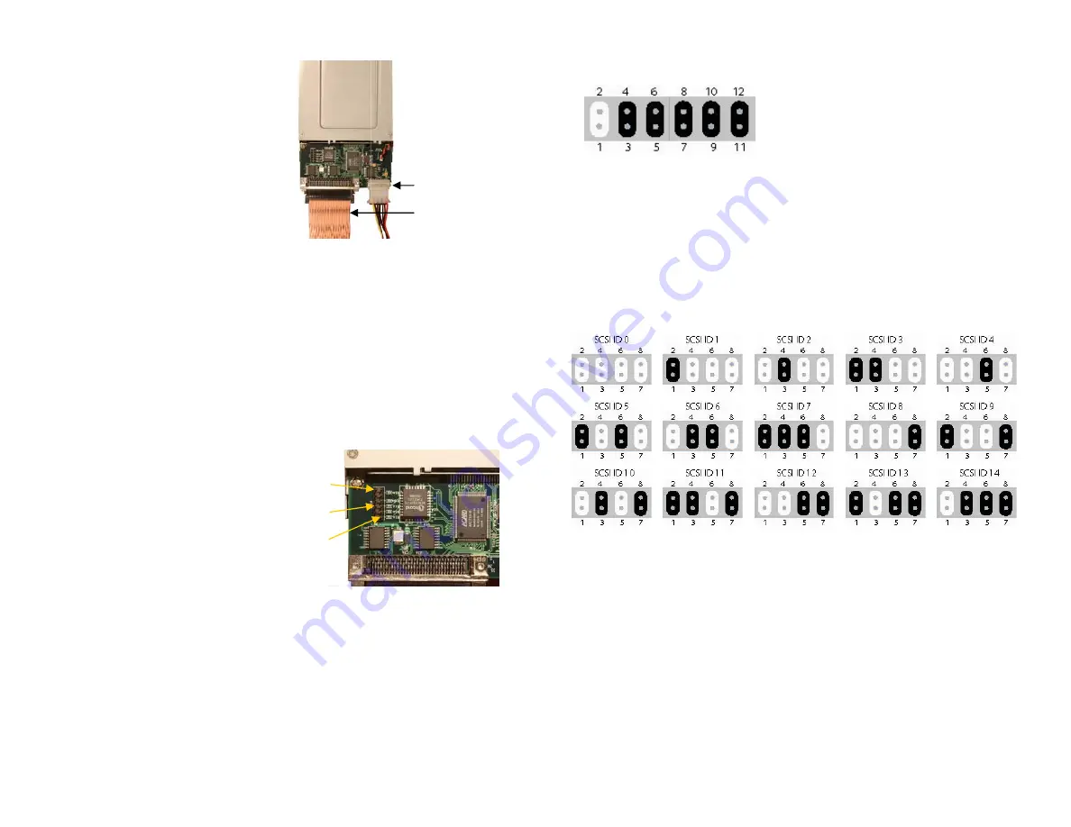
SCSI connector on the Ultra Wide
SCSI HardTape Bay PCB. (See
Figure 2).
Step 3.
Identify pin-1 of the SCSI ribbon cable connector. This will be
the same side as the colored line on the ribbon cable itself (See Figure 2).
Step 4.
Connect the SCSI ribbon cable connector to the Bay PCB
connector aligning pin-1 to pin-1.
Step 5.
Connect the 4-pin power cable to the Bay PCB.
Configuring jumper settings on your Ultra Wide SCSI HardTape Bay.
There are three functions to set via jumper
selection on the SCSI HardTape Bay JP2A
connector (See Figure 3):
•
Terminator enable/disable
•
Terminator power on/off
•
SCSI ID number setup
Please follow the instructions below to determine your jumper setting.
Step 1. Terminator Enable / Disable (pins 9-10)
When your device is at the end of the SCSI bus cable or there is only one
device on this cable, the terminator should be enabled. If you need to
disable the terminator, remove the factory installed jumper from pins 9
and 10 (see Figure 4).
Figure 3
Figure 2
Pin 1 68-pin SCSI
Connector
4-pin power cable
Pin 1 SCSI ribbon
Cable
Pin 12
JP2A
Pin 1
Pins
1, 3, 5, 7 : SCSI ID Number
2, 4, 6, 8 : SCSI ID Common Ground
9, 10 : Terminator Enable/Disable
11, 12 : Terminator Power On/Off
Figure 4
Step 2. SCSI ID Number (Pins 1-8)
For every device on one SCSI adapter card, there is a unique ID number
identifying that device. Use the information in Figure 5 to set a unique ID
number for your SCSI bay.
Step 3. Terminator Power (Pins 11-12)
Default setting is on. However, you can turn it off by removing the
jumper between pins 11 and 12.
Figure 5


