


CHAPTER 5: SPECIFICATIONS
Q-Series
®
– QFOT1310 Series Broadcast Transmitter User Manual
6-1
CHAPTER 6: FUNCTION GUIDE
FUNCTION GUIDE
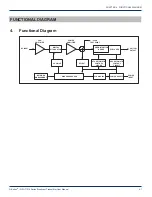
6. Function Guide
6.1. Front Panel Guide
1 ATX Trademark
2 LED Status Indicator:
Green light: normal; Red light: warning. Check VFD message to troubleshoot problem.
3 VFD Monitor:
Displays each status parameter, product model, serial number and other information about this
transmitter.
4 UP Button:
Scroll the VFD display UP, or increase setting value.
5 Down Button:
Scroll the VFD display DOWN, or decrease setting value.
6 Enter Button:
MGC mode select and ENTER button.
NOTE:
The default control mode of the FT13XX transmitter is AGC.
If the number of TV channels is less than 15
,
press the UP or DOWN button until the VFD displays “
MOD LEVEL=XX dBmV”
, then press the ENTER button to select
MGC mode. After selecting MGC mode, the VFD will display “
MOD LEVEL=XXdBmV”
and “
Please install…”
. At this
point the user can change the modulation level in 1 dB increments by pressing the UP or DOWN buttons. Once you
have selected the desired modulation level, press ENTER again to make it effective. At that time the VFD will display
“
MOD LEVEL=XX dBmV”
and transmitter will shift back to AGC mode. For instance, if user’s ideal Modulating level is
42
dBmV
, VFD would display
“MOD LEVEL= 42 dBmV”
after operations shown above. Please consult an ATX engineer
for help with this feature.
7 RF Input Test Port:
Standard 75Ω style F-style test port for RF signal on-line test. Level tested from this port is 20 dB
lower than the actual RF drive level to the laser.
6.2. Rear Panel Guide
8 RF Input Port:
Standard 75Ω American style F port, used for connecting RF signal and the equipment. Level in this input
port must be at the range of 15~25 dBmV. Too high level may damage laser.
Optimum input level is 17 dBmV.
*The input level above 17 dBmV may damage Laser. Please consult factory!
9 Optical Signal Output:
Optical signal output port, SC/APC, or optional FC/APC connector. There are invisible laser
emissions from Fiber output when laser is active!
*It would be dangerous to point this port toward the human body especially eyes when equipment is
energized!
10 RS-232 Standard Network Management Port (optional):
Use for connecting equipment with RS-232 port in network
management server.
11 Network Management Indicator
Front View
8
9
10
11 12 13
14
15 16 17
Rear View
2
3
4
5 6
7
1
Содержание QFOT1310 Series
Страница 4: ...ii This page left intentionally blank ...


