


ATX
Confidential & Proprietary
CHAPTER 2: SET-UP
THRESHOLD LEVEL SETTINGS
3. Threshold Level Settings
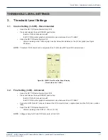
3.1. Coarse Setting (3-9 dB) - Recommended
•
Adjust the SET THD potentiometer fully CCW
•
Press and release the reset (RESET) push button:
◦
the B ACTIVE LED should turn
off
◦
the RF PWR level bar graph should indicate a level between 40 and 70 dBmV
•
Adjust the SET THD potentiometer CW:
◦
obtain a reading on the THD bar graph one bar below that indicated on the RF bar graph (see Figure
#4 below)
NOTE:
Threshold (THD) should not be set greater than 15 dB below RF Power (RF) indicator level.
3.2. Fine Setting (3 dB) - Advanced
•
Adjust the SET THD potentiometer fully CCW
•
Press and release the reset (RESET) push button:
◦
the B ACTIVE LED should turn
off
◦
the RF PWR level bar graph should indicate a level between 40 and 70 dBmV
•
Connect a DVM (Fluke 87 or equiv.) between the RF test point (black - negative lead) and the THD (red - positive
lead)
•
Adjust the SET THD potentiometer CW:
◦
obtain a reading on the DVM of -150 mV (-3 dB)
NOTE:
Voltage scaling for RF and THD test points is 50 mV/dB
MAXNET
®
– MNRS Redundant RF Detector/Switch Module – Installation & Operation Manual
3-1
CHAPTER 3: THRESHOLD LEVEL SETTINGS
Figure #4: MNRS Front Panel Bar Graph Display
(Threshold set for 3-9 dB)


