ATX Chromadigm-HQ Скачать руководство пользователя страница 15

MODULE SET-UP

Chromadigm CHS/CHQ Transmitter – Quick Start Guide 

4-3

4.2.1  AGC Mode 

Operating in the AGC mode provides for plug-and-play RF level setting as the transmitter automatically sets the internal 

attenuators for the optimal laser drive level and OMI. The following provides the procedures and associated menus for 

configuring the CHS or CHQ transmitter with the front panel display in the AGC mode. The CHS or CHQ transmitter will be 

in the AGC mode as a default.

1.  Connect power to the chassis.
2.  With a combined Broadcast/Narrowcast total RF power as determined in section 4.1, plug the Broadcast cable into 

the BC port and the four Narrowcast cables into the associated NC ports.

3.  From the front panel RF test points confirm the Narrowcast QAM RF channels are set to the same level as the 

Broadcast QAM RF channels on each port. If not, correct the level difference coming into the chassis on each 

individual NC port.

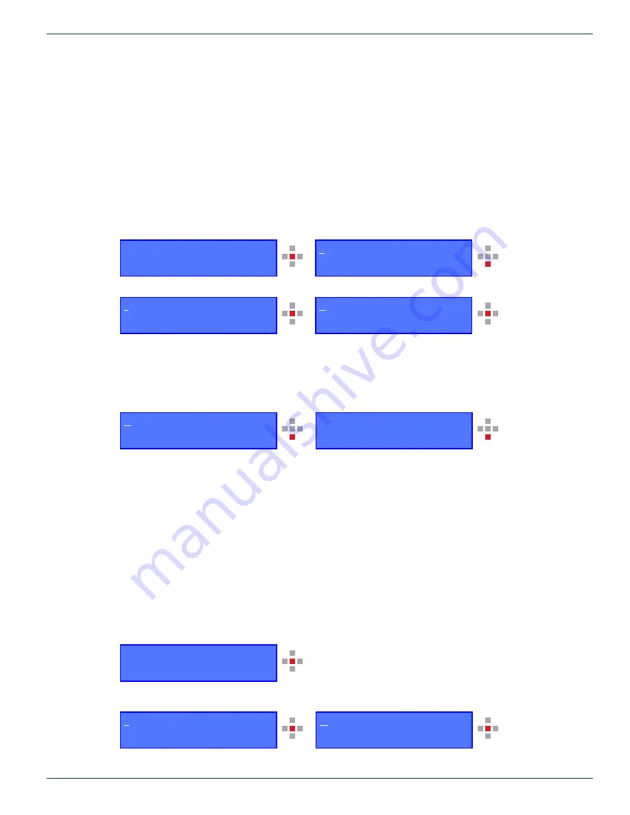
4.  Using the front panel menu navigate to the Tx Status Menu as follows. A CHS/CHQ with 12 dBm output power is 

utilized in the example.
Press center key to enter sub menus. Press the down key until the cursor is highlighted on the Tx Status Menu.

Press center key to advance to the Tx Status Menu.


This menu displays the optical power of each laser (OPT:) where each laser is displaying 12 dBm ± 0.2 dB and 

the “reference RF level” (RF:) is displaying the reference input level to each laser as 0 dB ± 0.5 dB which is the 

expected reference level with a rear panel RF input level of +38 dBmV total composite RF power of the BC and NC 

combined signal.

5.  Navigate to the RF menu to check for proper AGC reserve gain. Press the down key to move the cursor to the RF 

menu.


The RF menu now displays the reference RF level for each laser and the reserve gain “Att (dB)”, in this case +3.2. 

The reserve gain should be b3 to +4 with a rear panel RF input level of +38 dBmV total composite RF 

power of the BC and NC combined signal.
The set-up is now confirmed to be correct.

4.2.2  MGC Mode 

The following provides the procedures and associated menus for configuring the CHS or CHQ with the front panel display in 

the MGC mode.

1.  Connect power to the chassis.
2.  With a combined Broadcast/Narrowcast total RF power as determined in section 4.1, plug the Broadcast cable into 

the BC port and the four Narrowcast cables into the associated NC port.

3.  From the front panel RF test points, confirm the Narrowcast QAM RF channels are at the same level as the Broadcast 

QAM RF channels on each port. If not, correct the level difference coming into the chassis on each individual NC port.

4.  Using the front panel menu navigate to the Setup/Mode Settings menu.

Press center key to enter sub menus.

The cursor is on the Setup Menu, press the center key to enter the Setup Menu, and then press the center again 

key to enter Mode Setting.

CHAPTER 4: 

Setup Menu
Tx Status Menu

Mode Setting Menu
Gain Setting Menu

ATX Networks
Chromadigm Series AGC

ATX Networks
Chromadigm Series AGC

Setup Menu
Tx Status Menu

Tx Status Menu
Alarm Menu

OPT:   

1

2.0    

11

.8    

1

2.

1


1

2.2

RF   :     0.5    -0.2      0.0      0.4 

OPT:   

1

2.0    

11

.8    

1

2.

1


1

2.2

RF   :     0.5    -0.2      0.0      0.4 

RF          :     0.5    -0.2      0.0      0.4
Att (dB) :     +3.2 

Содержание Chromadigm-HQ

Страница 1: ...Chromadigm CHS CHQ Transmitter Quick Start Guide Patented U S 7 936 997 ...

Страница 2: ...r non ATX product and company names in this manual are the property of their respective companies Although every effort has been taken to ensure the accuracy of this document it may be necessary without notice to make amendments or correct omissions Specifications subject to change without notice ...

Страница 3: ...ion to 48 VDC Power Source 1 2 1 6 Fuse Replacement 1 2 1 7 Laser Safety 1 2 1 8 Laser Power Warning Labels 1 3 2 PRODUCT INTRODUCTION 2 1 3 BLOCK DIAGRAM OPERATION 3 1 4 MODULE SET UP 4 1 4 1 Setting RF Input Levels 4 1 4 1 1CHS All QAM Channels 4 1 4 1 2CHS Mix of Analog QAM Channels 4 1 4 1 3CHQ All QAM Channels 4 1 4 2 Configuring the CHS CHQ Transmitter 4 2 4 2 1AGC Mode 4 3 4 2 2MGC Mode 4 3...

Страница 4: ...iv Chromadigm CHS CHQ Transmitter Quick Start Guide This page intentionally left blank ...

Страница 5: ...rounding by using extension cables power cables or other devices on the mains power without a protective ground conductor If this equipment is equipped with an external grounding terminal attach one end of an 18 gauge wire or larger to the grounding terminal then attach the other end of the wire to a ground such as a grounded equipment rack 1 2 Installation Site When selecting the installation sit...

Страница 6: ...nnect this equipment only to the power sources that are identified on the equipment rating label Overcurrent protection breakers or fuses must be sized appropriately for the total current rating of the modules and accessories contained within a system chassis or multiple chassis that are connected to a common mains circuit This equipment may have two power sources Be sure to disconnect all power s...

Страница 7: ...y be installed operated and serviced by authorized personnel trained in the safe handling and operation of fiber optic cables and laser sources Do not apply power to this equipment if the fiber is unmated or unterminated Do not look into an activated fiber with optical instruments such as magnifiers or microscopes 1 8 Laser Power Warning Labels This equipment may contain or be connected to other e...

Страница 8: ...SAFETY 1 4 Chromadigm CHS CHQ Transmitter Quick Start Guide CHAPTER 1 This page intentionally left blank ...

Страница 9: ...ving to retune the transmitter when switched between different lengths of fiber The CHS CHQ transmitter with its innovative technology sets the performance standard in DWDM full band systems offering a unique set of benefits Chirp cancellation for distance independent performance Adaptive clipping mitigation for error free QAM performance High OMI for superior CNR MER performance Full utilization ...

Страница 10: ...PRODUCT INTRODUCTION 2 2 Chromadigm CHS CHQ Transmitter Quick Start Guide CHAPTER 2 This page intentionally left blank ...

Страница 11: ... the feedback loop when operated in the AGC mode or may be set in the manual mode via the chassis controller interfaces same as the BC operation The NC channels are then combined with the BC channels creating a full spectrum of channel loading from 54 1002 MHz The combined signal is coupled to a 20 dB front panel RF test point The signal is amplified and then passes through a directional coupler u...

Страница 12: ...BLOCK DIAGRAM OPERATION 3 2 Chromadigm CHS CHQ Transmitter Quick Start Guide This page intentionally left blank CHAPTER 3 ...

Страница 13: ...8 dBmV 22 16 dBmV Using the same formula to adjust for a lower channel loading such as a 750 MHz system with 110 channels 38 dBmV 10 log10 110 38 dBmV 20 4 17 6 dBmV Therefore with 110 of all QAM channel loading the correct rear panel RF input level is 17 6 dBmV at the input of both the BC and NC ports 4 1 2 CHS Mix of Analog QAM Channels The mix of analog and QAM reference channel loading and per...

Страница 14: ... limited number they do not contribute much to the total power 4 2 Configuring the CHS CHQ Transmitter The set up configuration and verifying the RF drive level for the CHS CHQ transmitter requires the operator to become familiar with the front panel configuration menus Refer to the ATX Document No 2000010 Chromadigm Chassis User Interface as a supplement to the following procedures which will ref...

Страница 15: ... a rear panel RF input level of 38 dBmV total composite RF power of the BC and NC combined signal 5 Navigate to the RF menu to check for proper AGC reserve gain Press the down key to move the cursor to the RF menu The RF menu now displays the reference RF level for each laser and the reserve gain Att dB in this case 3 2 The reserve gain should be between 3 to 4 with a rear panel RF input level of ...

Страница 16: ...r gain step setting Gain steps The gain setting is adjusted for a RF Level of 0 0 0 5 dB In the example below the reference level is 1 0 so the attenuator needs to be adjusted Press the down key to move the cursor to Gain Steps 8 Adjust the Gain Steps to add or remove the attenuation steps until the RF Lvl displays 0 0 dB 0 5 dB in the Tx Status RF menu Press the select key and press the right or ...

Страница 17: ...each port The RF menu now displays the reference RF level for each laser and the reserve gain Att dB in this case 3 2 The reserve gain should be between 3 to 4 with a rear panel RF input level as determined in section 4 1 for the total composite RF power of the BC and NC combined signal The set up is now confirmed to be correct CHAPTER 4 Gain steps 2 5 Save Yes 2 5 Tx Status Menu Alarm Menu RF 0 5...

Страница 18: ...MODULE SET UP 4 6 Chromadigm CHS CHQ Transmitter Quick Start Guide This page intentionally left blank CHAPTER 4 ...

Страница 19: ... Chromadigm TranScend COMPASS ART TECHNICAL SUPPORT Tel 408 227 3400 press 4 Fax 408 227 3403 Email opticalsupport atxnetworks com CUSTOMER SERVICE ATX Networks 5850 Hellyer Avenue San Jose CA 95138 USA Tel 408 227 3400 press 4 Fax 408 227 3403 Email opticalsales atxnetworks com Web www atxnetworks com 5 2 Warranty Information All of ATX Networks products have a 1 year warranty that covers manufac...

Страница 20: ...Printed in Canada Rev 11 17 ANW1163 5850 Hellyer Avenue San Jose CA 95138 USA Tel 1 408 227 3400 Fax 1 408 227 3403 www atxnetworks com opticalsupport atxnetworks com ...

Отзывы: