Attero Tech BoomBox NA4 Скачать руководство пользователя страница 10


BoomBox NA4 


User Manual 

 Attero Tech LLC 2011-2013 

Page 6 

614-00006-02 


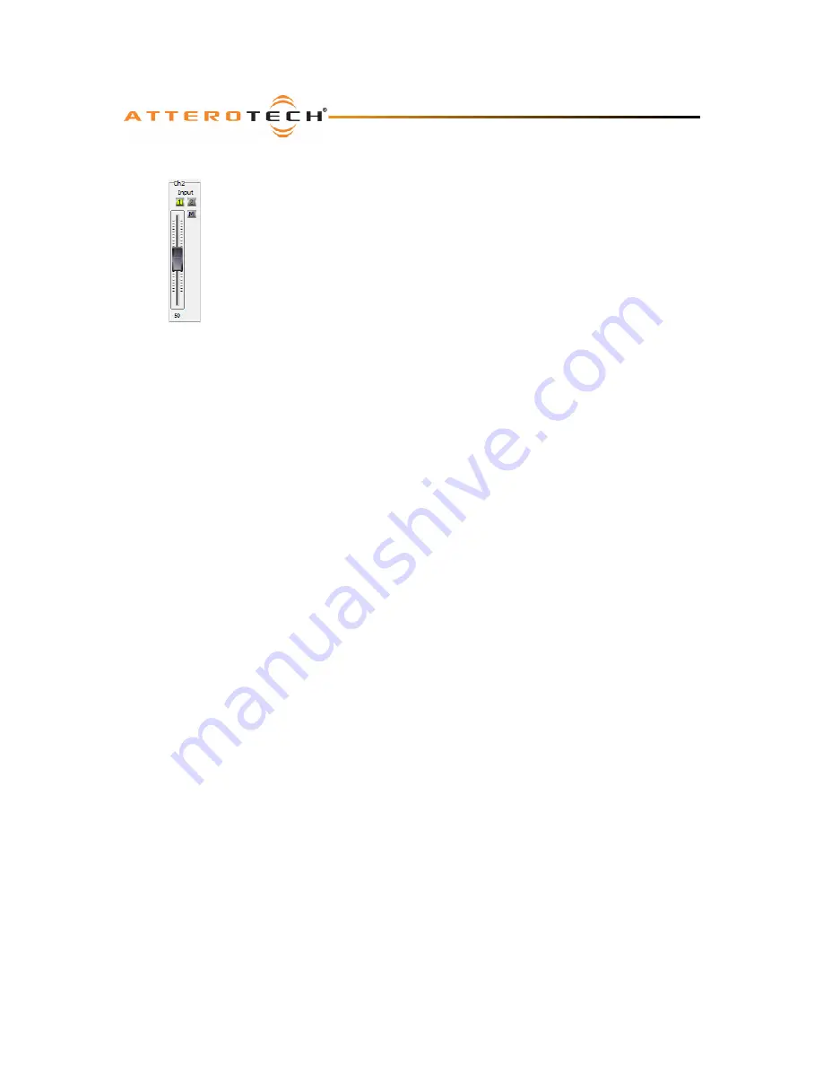
3.2.2 – Channel Controls 

Each individual output has its own local set of controls (see Figure 5).  At the top is the 
channel select.  This allows selection of which of the two possible audio streams to use for 
that particular output.  Which audio streams are available is determined by the bundle 
setup.  The active channel button will show green, and the inactive channel button show 
grey.  One or the other of the channel select buttons will always be active.  To select the 
other audio stream, simply click the inactive channel select button. 
 
There are no restrictions on how many outputs on a given unit can use a particular audio 
stream or in which order the streams are allocated to the outputs.  The channel selection 
can also be changed on the fly. 
 
Slightly below that is the mute button (marked with an ‘M’).  When the button is grey, as 
shown in Figure 5, the mute is not active.  When the button is grey, the mute is active.  
Clicking the mute button will turn it toggle the mute on or off.  The channel mute only 
affects an individual output. 
 
The main control is the volume fader.  The fader has a minimum value of 0 and a maximum 
of 100 Is this still true, or have we audio scaled this?.  Moving the fader up increases the 

volume, moving it down reduces it.  Altering the value will change the volume on that channel only.  Click and hold the 
left mouse button down on the slider and drag the mouse forward or backward to move the slider upward or downward 
respectively.  The new volume value is sent to the BoomBox once the mouse button is released. 
 
The volume control also accepts a value that is typed in.  A single left click on the control will highlight the volume 
controls text value and typing a new value will overwrite the current text.  Once the required value is entered, press the 
Enter key to complete the process and accept the new value.  If a valid number is entered, the control will change to the 
newly entered number or as close to it as the control’s range allows.  The control will revert back to its previous value if 
an invalid number is entered.  If the Enter key is not pressed after entering a new value and a different control is 
selected, the control that was being edited will revert to its previous value. 


Figure 5 – Channel 

Controls 

Содержание BoomBox NA4

Страница 1: ...Attero Tech LLC 1315 Directors Row Suite 107 Ft Wayne IN 46808 Phone 260 496 9668 Fax 260 496 9879 www atterotech com 614 00006 02 BoomBox NA4 User Manual Date 05 30 13 Revision 02...

Страница 2: ...rticularly at plugs convenience receptacles and the point where they exit from the apparatus 11 Only use attachments accessories specified by Attero Tech 12 Use only with the cart stand tripod bracket...

Страница 3: ...rotection against harmful interference when the equipment is operated in a commercial environment This equipment generates uses and can radiate radio frequency energy and if not installed and used in...

Страница 4: ...tion 3 2 1 Mechanical 3 2 2 Electrical 4 3 Configuration 5 3 1 Audio Configuration 5 3 2 Output Controls 5 3 2 1 Master Controls 5 3 2 2 Channel Controls 6 4 Troubleshooting 7 4 1 Checking the Network...

Страница 5: ...tandard IEEE802 3at compatible PoE network switch or injector or by using an external 12V 24V DC source Note Maximum output power from a BoomBox requires using either an IEEE802 3at PoE switch or a 12...

Страница 6: ...Audio AutoSwitch DC Selector 3 3V RJ45 Regulated 12 to 24VDC 12V 24V XFMR Speaker Output Speaker Output Speaker Output Figure 1 System diagram of a BoomBox The BoomBox system is shown in Figure 1 Pow...

Страница 7: ...us will need attaching to the BoomBox prior to installation into the rack The rack kits comprise of rack ears and rack extension pieces The dual rack kit also has an additional center spacer plate All...

Страница 8: ...ch the CobraNet I F port to a spare port on the CobraNet network switch using a CAT 5 cable o Attach the power supply to the power input jack and then power up the external supply If all steps are per...

Страница 9: ...ticular receiver submap table If more than one field has 33 or 34 and both bundles are active the output audio may not be what is expected Figure 3 shows a receiver setup where both audio streams are...

Страница 10: ...channel mute only affects an individual output The main control is the volume fader The fader has a minimum value of 0 and a maximum of 100 Is this still true or have we audio scaled this Moving the f...

Страница 11: ...the power light on the switch injector is on o If using the optional wall wart check power is supplied and the power light is on o Ensure the PC is running Windows 98SE or later Windows 95 is not sui...

Страница 12: ...he CobraNet interface shall be compatible with Attero Tech Control Center software monitoring in system applications The CobraNet interface shall be compliant with the RoHS directive The CobraNet inte...

Страница 13: ...cifically for CobraNet such as Attero Tech s Control Center application The figure above represents the types of data that coexist on a CobraNet network Before a CobraNet system can be configured it i...

Страница 14: ...sed from one device to the other It should be noted that no knowledge of a device s network topology or connection is thus required in order to configure audio connections The only restriction to this...

Страница 15: ...anual Attero Tech LLC 2011 2013 Page B 1 614 00006 02 APPENDIX B Reference Documents The following table lists the relevant reference documents Document Title Revision CobraNet Programmer s Reference...

Отзывы: