Atmos InterCombi
ATMOS
Installation Instructions
Atmos Heating Systems
West March
Daventry
Northants, NN11 4SA
Tel: 01327 871990
Fax: 01327 871905
e-mail:
[email protected]
internet: www.atmos.uk.com
Issue 1.4.05
Страница 1: ...InterCombi ATMOS ATMOS Installation Instructions Atmos Heating Systems West March Daventry Northants NN11 4SA Tel 01327 871990 Fax 01327 871905 e mail sales atmos uk com internet www atmos uk com Issue 1 4 05 ...
Страница 2: ...uct specifications that deviate from the standard model The information provided has been compiled with the utmost care However Atmos Heating Systems cannot be held liable for any faults in the information nor for the consequences thereof Atmos Heating Systems cannot be held liable for any damage resulting from the activities carried out by third parties To be changed without prior notice 2 ...
Страница 3: ...and the mounting bracket 17 4 5 3 Fitting the top connecting frame 17 4 5 4 Installation connections 17 4 6 Mount the appliance 18 4 7 Fit the pipework cover 18 5 Connections 19 5 1 Connect the CH system 19 5 1 1 Expansion vessel 19 5 1 2 Thermostatic radiator valves 19 5 1 3 System bypass 19 5 1 4 Underfloor heating 20 5 2 Hot water system 21 5 2 1 Appliance with pre heating by solar system 21 5 ...
Страница 4: ...ly 38 6 1 3 Gas supply 38 6 2 Commissioning of the appliance 39 6 3 System Shutdown 40 6 3 1 Frost protection 40 7 Setting and Adjustment 41 7 1 Directly via operating panel 41 7 2 Settings through the service code 41 7 3 Parameters 42 7 4 Setting maximum CH power 43 7 5 Setting pump position 43 7 6 Weather dependent control 44 7 7 Conversion to other gas type 44 7 8 Gas air control 44 7 9 Setting...
Страница 5: ...heater Appliance Appliance with piping for central heating CH system Appliance with piping for domestic water HW system Icons The following symbols are used in this manual CAUTION Procedures that when not carried out with due care may result in damage to the product or the environment or in personal injury Service and technical support For information about specific adjustments installation mainte...
Страница 6: ...e or injudicious treatment or to unskilful repair adjustment installation or maintenance by non approved installers 6 The guarantee is no longer valid when the defect is the result of deposition of scale harmful to the appliance and the system Surface damage and transport damage are outside the scope of the guarantee The right to guarantee lapses if the boiler has not had a yearly service by an ap...
Страница 7: ... or local Water byelaws 1 2 CH system The entire system should comply with the valid safety regulations as mentioned in BS 5449 Central Heating for Domestic Premises 1 3 Gas system The entire system should comply with the valid safety regulations as mentioned in BS 6798 Specification for installation of gas fired hot water boilers of rated input not exceeding 60 kW BS 6891 Installation of low pres...
Страница 8: ...atural gas G20 A conversion kit for propane G31 can supplied upon request 2 2 Operation The Atmos InterCombi wall mounted gas heater is a modulating high efficiency boiler This implies that the power is adjusted to the heat demand In the aluminium heat exchanger two separate copper circuits have been integrated Because of the separated circuits for central heating and hot water the heating and the...
Страница 9: ...ilate At starting the appliance the fan is first brought to the starting speed When reaching the starting speed the burner is ignited Code 3 is also visible when after stopping the burner post purge takes place 4 Ignite When the fan has reached the ignition speed the burner is ignited by means of electric spark ignition During ignition the code 4 appears If the burner is not ignited another igniti...
Страница 10: ...erature is displayed on the operating panel During domestic hot water operation the actual domestic hot water supply temperature can be read by pressing the service key 7 Heating the appliance For a quick supply of domestic hot water a comfort function has been provided in the controller This function keeps the heat exchanger at the correct temperature This comfort function has the following setti...
Страница 11: ...for protecting its heat exchanger as described below NOTE However to avoid the condensate freezing the boiler must be installed in a FROST FREE room In order to avoid freezing of the appliance heat exchanger it has an appliance frost protection When the temperature of the heat exchanger drops to 5ºC the burner will be activated and the pump will start running until the temperature of the heat exch...
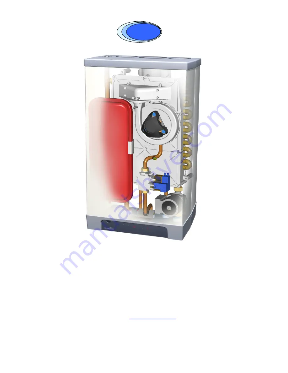
Страница 12: ...S2 P Hot water sensor S3 F Fan Q Siphon G Flow switch R Heat exchanger H Pressure gauge S Operating panel and display I 1m connecting cable 230 V Note Plug must be removed T Ionisation ignition probe J Manual air vent U Position type plate K Sight glass and mirror Additional Components supplied T piece Pressure relief safety valve 3 bar supplied in boiler box Valve set supplied separately with boi...
Страница 13: ...ly and return 22 mm diameter Connection cold and hot water 15 mm diameter Connection gas female thread Mounting strip boiler Bag with fixings Mounting frame for top pipe connection Pipework cover Outside sensor Conversion set to Propane LPG or G31 Interface cable 13 ...
Страница 14: ...rCombi HE 32 B CH return 22 mm diameter I C Gas 15 mm diameter H 810mm InterCombi HE 32 D Cold water 15 mm diameter E Domestic hot water 15 mm diameter Z Flue gas outlet 80 mm diameter F Condensate 32 mm dia after siphon 25 mm dia flexible Y Air supply inlet 80 mm diameter 14 ...
Страница 15: ...Pressure relief safety valve 3 bar Installation instructions Guarantee card Valve set supplied separately with boiler 3 Check the appliance for any damage report damage to the Supplier immediately 4 3 Additional dimensions The diagram shown below gives additional dimensions primarily for the mounting arrangement using the OPTIONAL mounting bracket 15 ...
Страница 16: ...led in a frost free room Keep 5 cm free space above the appliance in order to be able to remove the front panel from the casing 4 4 1 Installation in a kitchen cupboard Make sure there is sufficient ventilation above and below the appliance When the appliance is placed in a small cupboard ventilation openings of at least 50 cm2 must be made 4 4 2 Installation in an airing cupboard Compartment vent...
Страница 17: ...t horizontally to the wall according to the drilling pattern using the fastening materials supplied 2 Mount the parts of the various connecting sets Note that the 3 bar pressure relief valve must be installed on the boiler side of the CH flow valve see diagram 4 5 3 Fitting the top connecting frame 1 Fasten the frame vertically to the wall using the fastening materials supplied 2 Fasten the pipe m...
Страница 18: ...milar to arrangement for washing machine The 15 mm safety discharge copper pipe from the pressure relief safety valve may also be taken into this pipe as shown in the diagram 5 1 or alternatively taken to a safe discharge position on the outside wall of the building 4 Tighten the clamping fittings to the mounting bracket 5 Mount the air supply and the flue discharge 6 Close the air supply opening ...
Страница 19: ...ipe see also 5 1 1 A non return valve when pipes are running upward at a short distance from the appliance This prevents a gravity effect during domestic hot water operation of the appliance 5 1 1 Expansion vessel The appliance is fitted with a 6 litre expansion vessel which is adequate for a system with a water volume not exceeding 100 litres typically 8 radiators For larger volume systems an add...
Страница 20: ... pump of the CH circuit Connect underfloor heating with an electric shut off valve two way valve to prevent circulation through the appliance when there is no demand for central heating A Boiler B Pump C Thermostatic control valve D Spring operated non return valve E Electrical shut off valve 230 V F Radiators G Room clock thermostat H Maximum thermostat 20 ...
Страница 21: ...nnected or filled If the appliance is shutdown during the winter the domestic hot water should be drained to prevent freezing For this the cold water connection at the bottom of the appliance must be disconnected A Not applicable B InterCombi HE32 X Water pipe pressure in bar Y Water flow rate in l minute 10 5 2 1 Appliance with pre heating by solar system A connecting set for appliances with the ...
Страница 22: ...nected via a double pole isolating switch fitted with a 3 amp fuse The switch must be readily accessible within 1m of the appliance and provide complete electrical isolation for the boiler and control system The appliance is supplied factory wired complete with 1 m of mains cable Note the plug must be removed from the cable All electrical connections to the mains supply must be made in full accord...
Страница 23: ...ireless room thermostat is employed consult the manufacturer s instructions for installation Note Under no circumstances must any electrical power be input to the room thermostat terminals It is a volt free switch Note Care must also be taken to avoid induced voltages caused by the running of the thermostat cables along side mains voltage cables 5 4 3 Outside temperature sensor The appliance has a...
Страница 24: ... connection Using the concentric adapter set the standard two pipe connection can be changed into a concentric connection 1 Seal the open air supply connections in the appliance with the sealing cap delivered with the set foam plug 2 Remove the sealing ring around the flue discharge in the appliance 3 Fit the sealing ring ø 116 x 110 mm 4 Fit the adapter on the flue discharge 5 5 3 Pipe materials ...
Страница 25: ...Note Due to the low flue gas temperature pluming will occur at the flue terminal Care should be taken to ensure that the discharge plume will not cause annoyance to the customer or neighbours It is generally recommended that flues should discharge vertically at roof level In this position pluming is not normally a problem 5 5 5 Flue system The flue system must be installed in accordance with BS544...
Страница 26: ...s and the lengths of the equivalent pipe lengths of bends The maximum length of the 80 125mm concentric pipe is 24 m for horizontal pipe and 27 m for vertical pipe 5 6 1 Equivalent lengths Bend at 90 R D 1 2 m Bend at 45 R D 1 1 m Elbow at 90 R D 0 5 4 m Elbow at 45 R D 0 5 2 m Note The type supplied by Atmos are Elbows For smaller twin pipe diameters the maximum pipe length is reduced as follows ...
Страница 27: ...discharge pipe into the discharge stub of the appliance 2 Slide the flue discharge pipes into each other From the appliance all pipes must be slid into the previous one 3 Mount a non vertical flue discharge pipe in a slope to the appliance min 50 mm m 4 Mount the folded seams directed upwards in a horizontal part 5 Tape up non gastight connections with heat and moisture resistant aluminium tape Th...
Страница 28: ... pipes diameter 80 mm B Outlet grid C Wall cover plate 2x Maximum pipe length See 5 6 Flue discharge pipe and air supply pipe For mounting see 5 6 5 Mounting twin pipe terminal 1 Make two openings of diameter 90 mm at the place of the outlet 2 Cut the pipes to the correct length 3 Slide the supply and discharge pipes into the openings 4 Cover the openings with wall cover plates 5 Mount the outlet ...
Страница 29: ...as a console or separating wall and when the outlet is not at the edge of a building the air supply pipe does not need extension 1 Extend the flue discharge pipe and if necessary also the air supply pipe of the terminal with standard flue discharge and air supply pipes to the correct length required 2 Slide the flue discharge pipe and if necessary also the air supply pipe into the discharge and su...
Страница 30: ...orizontal B Atmos concentric pipe For extension of a balcony gallery outlet Maximum pipe length See 5 6 Flue discharge and air supply pipes For mounting see 5 6 5 Mounting 80 125mm horizontal terminal B 1 Make an opening of diameter 130 mm at the place of the outlet 2 Shorten the terminal to the length required 3 Mount the outlet grid and attach this to the inside pipe 4 Slide the terminal into th...
Страница 31: ...al 2 Shorten the combination terminal or the combination extension pipe to the correct length required 3 Mount the outlet grid and attach this to the inside pipe 4 Mount the combination terminal and combination extension pipe in a slope to the appliance 5 9 Roof outlet combination and twin pipe terminal vertical Appliance category C33 CAUTION When the Atmos combination terminal vertical cannot be ...
Страница 32: ...itched roof On a flat roof an adhesive plate for a pipe of diameter 126 mm must be applied 2 Dismount the manifold of the combination terminal C 3 Slide the combination terminal C from the outside to the inside With a pitched roof through the vertical terminal tile with shell With a flat roof through the adhesive plate 4 Mount the manifold of the combination terminal C and lock it with a sheet met...
Страница 33: ...g discharge cover on a pitched roof at the place of the outlet 2 Mount a ventilating passage diameter 80 mm with cross cut in the corresponding roof passage tile for the air supply 3 Mount for the flue discharge a double walled flue terminal diameter 80 mm with Giveg discharge cover at the place of the outlet Mount with a flat roof or a constructional chimney and for the air supply a ventilating p...
Страница 34: ...attack ice formation rain ingress etc In view of the different models and requirements the prefabricated chimneys must be adjusted to the local situation a gas certificate is not required CAUTION The connection of the air supply and the flue discharge between the appliance and the prefab chimney must be made in pipes of diameter 80 mm Maximum pipe length See 5 6 Flue discharge and air supply pipes...
Страница 35: ...ply 2 Shorten the air supply pipe to the correct length out of the wall 3 Mount the Atmos inlet grid and attach this to the pipe 4 Slide the air supply pipe into the opening and cover the opening with a rosette if necessary 5 Mount the air supply at the place of the outside wall terminal in a slope to the outside to prevent rain from entering Mounting flue terminal vertical 1 Mount a roof tile wit...
Страница 36: ...th The maximum length of the air supply and flue discharge pipes between appliance and common flue discharge and air supply together is 75 metres Flue discharge pipe and air supply pipe For mounting see 5 6 5 Common flue discharge The outlet of the flue discharge can be made at any place in the pitching roof surface provided that the outlet in the roof surface has the same orientation as the air s...
Страница 37: ... cover a certificate of incorporation from the Gastec Gasinstituut is required The common air supply and the common flue discharge may be made concentrically or separately Maximum pipe length The maximum length of the air supply and flue discharge pipes between appliance and CLV system together is 75 metres Flue discharge pipe and air supply pipe For mounting see 5 6 5 Remark The passage of the co...
Страница 38: ...ounted to the appliance instead of the manual air vent 3 De aerate the system with the manual air vents on the radiators 4 Fill up the CH system when the pressure has dropped too low as a result of the de aerating 5 Check all joints for leaks 6 Fill the siphon with water important 6 1 2 Hot water supply 1 Open the main tap in order to pressurise the hot water part 2 De aerate the heat exchanger an...
Страница 39: ...ce panel See Setting of maximum power If necessary change the pump position and or the radiator valves The minimum flow through is 200 l h at a set power of 7 0 kW 750 l h at a set power of 26 2 kW 7 Switch off the electrical supply to the appliance 8 De aerate the appliance and the system after cooling down fill up if necessary 9 Check the heating and the hot water supply for proper operation 10 ...
Страница 40: ...condensate discharge pipe the appliance should be installed in a frost free room In order to avoid freezing of the appliance heat exchanger it has an appliance frost protection When the temperature of the heat exchanger drops to 5ºC the burner will be activated and the pump will start running until the temperature of the heat exchanger reaches10ºC When the system or a part thereof can freeze a fro...
Страница 41: ...sing the hw store key and it has the following settings Eco The comfort function is self learning The appliance is inactivated during the night or after a long absence The appliance adjusts to the User pattern of the domestic hot water requirements On The comfort function of the appliance is continuously activated The appliance always supplies domestic hot water immediately Off Both LED s off The ...
Страница 42: ...ctive with external MIT switch 3 Set CH power 70 Setting maximum CH load 4 Set hw power 99 Setting maximum hw power 5 Min supply temperature of the control line 25 Setting range 10 C to 25 C Weather dependent control 6 Min outside temperature of the control line 7 Setting range 9 C to 10 C Weather dependent control 7 Max outside temperature of the control line 25 Setting range 15 C to 30 C Weather...
Страница 43: ...while burning modulation by time and decreases as soon as the set supply temperature is reached 7 5 Setting pump position The switch for setting the pump position is located on the connecting box of the CH pump 1 Set the pump position on the basis of the set maximum power and the resistance of the system on the water side See diagram Pressure loss and pump lift type Ups 50 130 positions 1 2 and 3 ...
Страница 44: ...f the electrical supply to the appliance 2 Close the gas tap 3 Remove the front cover of the appliance 4 Disconnect the coupling 1 above the gas valve and turn the gas mixing pipe 2 backwards 5 Replace the O ring 3 and the gas setting ring 4 by the rings of the conversion set 6 Reassemble in reverse order 7 Open the gas tap 8 Check the gas connections for tightness leaks 9 Switch on the electrical...
Страница 45: ...hose 3 Switch on the appliance using the on off key 4 Set the boiler to the lowest output by simultaneously pressing the service and keys on the operating panel until an L appears on the service display 5 Measure the CO2 value If the CO2 value does not correspond with the value in the table proceed as follows for setting 6 Remove the front cover of the appliance 7 Remove the cover cap A with a fla...
Страница 46: ...oiler to the lowest power by simultaneously pressing the service and keys on the operating panel until an L appears on the display 6 Read the pressure This should be about 5 Pa or 0 05 mBar min 10 max 0 Pa or min 0 1 mBar 10 max 0 mBar When this is not the case proceed as follows for setting 7 Remove the cover cap A with a flat screwdriver 8 Set the pressure using setting screw B clockwise higher ...
Страница 47: ...wires for breaks Replace boiler sensor S1 and or S2 1 Temperature too high Air in system Pump does not run Too little circulation in system radiators closed pump setting too low 2 Exchange S1 and S2 Check the cable loom Replace S1 or S2 4 No flame signal after 4 ignition attempts Gas tap closed Incorrect ignition distance Gas inlet pressure too low or disappears Gas valve or ignition unit does not...
Страница 48: ... gas pipe Air in the gas pipe Yes No Inlet pressure too low Yes No No ignition Yes No No spark Yes Ignitionunit on gasunit faulty No Gas air control not Yes adjusted properly No Fan faulty or Yes No Fan blockage Yes No Gas val faulty ve it Yes Possible causes 1 The house gas meter may be faulty Inlet pressure too high Yes Contact the gas company No 1 Check the adjustment See Gas air control 1 Repl...
Страница 49: ...ermostat weather dependent control not closed or faulty 2 Replace the thermostat Yes 3 Replace the weather dependent control No 1 Check the voltage 2 Check the connector x4 3 Replace defective pump 4 Replace defective controller 1 Replace sensor S1 or S2 See Fault code display 1 or 2 1 See Burner does not ignite Burner does not ignite Yes No Burner does not operate on CH Sensor S1 or S2 faulty Yes...
Страница 50: ...ution 2 Clean appliance and flue system Possible causes 1 Check the setting and adjust if Room thermostat settings not correct Yes necessary set to 0 1 A No 1 Raise the pump setting or replace the pump 1 Check for circulation at least 2 or 3 radiators must be open 1 Adjust the power see Setting maximum CH power 1 Descale or flush the heat exchanger on the CH side No heat transfer due to scaling or...
Страница 51: ... Yes Yes 1 Set the hot water circuit to 60ºC dependent on the required temperature Temperature setting water circuit too low Yes No No 1 Cold water temperature 10ºC Yes No Possible causes Remedies Table 6 NTC resistances NTC 12 kOhm T C R ohm T C R ohm T C R ohm 15 76020 25 12000 65 2752 10 58880 30 9805 70 2337 5 45950 35 8055 75 1994 0 36130 40 6653 80 1707 5 28600 45 5522 85 1467 10 22800 50 46...
Страница 52: ...ttom with a brush or with compressed air 12 If necessary clean the bottom side of the heat exchanger and the condensate discharge at the bottom of the flue discharge behind the heat exchanger 13 Clean the siphon and the condensate discharge pipe 14 After cleaning fill the siphon with water 15 Replace the baffles in the heat exchanger 16 Check the silicone gasket of the front cover for damage hair ...
Страница 53: ...water temperature C 60 CH Nom load upper value kW 8 0 30 3 Nom load lower value kW 7 2 27 3 Nom power at 80 60 C kW 7 0 26 2 Nom power at 50 30 C kW 7 7 26 8 Max CH water pressure bar 3 Max CH water temperature C 90 Other data Gas consumption m3 h 0 85 3 85 Pressure loss appliance mWk Electrical data Mains voltage V 220 Safety class IP44 B IP20 Consumed power full load W 105 Consumed power partial...
Страница 54: ...10 1 Electrical diagram Note F1 5x20mm anti surge fuse 2A 54 ...
Страница 55: ...hine directive 89 392 EC as amended in directive 93 68 EC Low voltage directive 73 23 EC as amended in directive 93 68 EC Directive concerning gas appliances 90 396 EEG Boilers Efficiency Directive for new oil and gas fired central heating boilers 92 42 EC EMC Directive 89 336 EC as most recently amended in directive 93 68 EC 55 ...