Atmel QT600 Quick Start Guide
4
Atmel QT600 Quick Start Guide
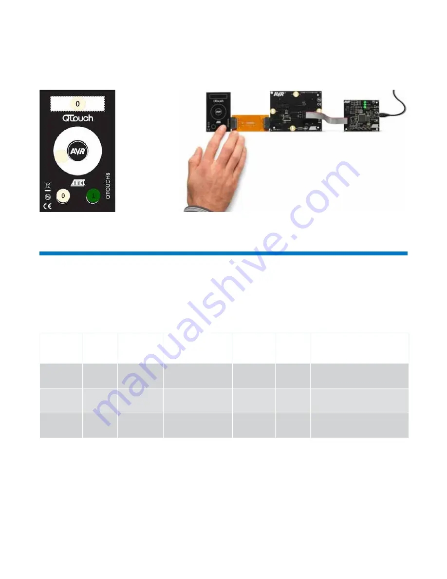
Figure 3 – Atmel QTouch8 Sensor
Board Displayed on CPU Monitor
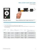
Figure 4 – Complete Set-up for the Atmel QTouch8 sensor board: The sensor board is
connected to the ATtiny88, which in turn is connected to the interface board
Sensor Board /
MCU Board
1.2)
To Program
1.6.1)
Main Lab - Device
and Signature Bytes
1.61)
Main Tab - Programming Mode
and Target Settings
1.7)
HW Setting tab
1.11)
To Program
and Run
1.8)
Program Tab --> Flash Hex Files
c:\Programs Files\Atmel_QTouch_Libaries_4.3\
Generic_QTouch_Libraries\AVR_Tiny_Mega_
XMega\
QTouch8 /
ATtiny88
6-conductor
ribbon cable
into ISP pins
ATtiny88
ISP Mode
(Settings = ISP Frequency =
200kHz)
VTarget = Target
Voltage: 3.3V
(click Write)
10-conductor
ribbon cable
into TOUCH
DATA
QTouch\example_projects\
QT600_ATtiny88_gnu.hex
ATouch16 /
ATXMEGA128A1
10-conductor
ribbon cable
into JTAG pins
ATxmega128A1
JTAG Mode (Settings = ‘Target
device is not part of a JTAG daisy
chain’)
VTarget = Target
Voltage: 3.3V
(click Write)
10-conductor
ribbon cable
into TOUCH
DATA
QTouch\example_projects\
QT600_ATxmega128a1_qt16_gnu.hex
QMatrix 8x8 /
ATmega324
10-conductor
ribbon cable
into JTAG pins
ATmega324PA
JTAG Mode (Settings = ‘Target
device is not part of a JTAG daisy
chain’)
VTarget = Target
Voltage: 3.3V
(click Write)
10-conductor
ribbon cable
into TOUCH
DATA
QMatrix\example_projects\
QT600_ATmega324_qm64_gnu.hex
Touch Solutions
Connect Kit Modules
2
QTouch16 with ATmega324 and QMatrix 8x8 with ATXMEGA128A1
2.1
By using the table below and following the same procedures as in step number 1 above, you can program and run
both of these boards


