background image

AT-OMNI-121 / AT-OMNI-122

22

Configuration

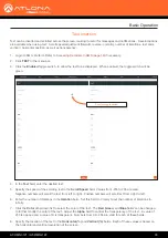
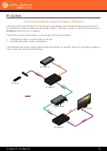
Configuring a Static IP Address

The following section is only required to set the decoder, currently in Auto IP mode, to a static IP address.  If a DHCP 

server is not found within 60 seconds, decoders are automatically placed in Auto IP mode and will be assigned an IP 

address within the range 

169.254.xxx.xxx

.   If this occurs, a static IP address can be assigned to the decoder in order 

for AMS to locate it on the network.

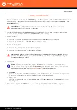
1. 

Make sure that the decoder is powered.  Power will need to be supplied either by the external 48V power supply 

(not included) or by connecting an Ethernet cable from the decoder to a PoE-capable switch.  If using the


AT-OMNI-122, the Ethernet cable can be connected to either 

ETHERNET 1

 or 

ETHERNET 2

.

2. 

Connect an Ethernet cable from the PC, directly to one of the Ethernet ports on the decoder.  Make sure that the 

computer being used has AMS installed.

3. 

Configure the PC to a static IP address that is on the same subnet as the decoder.


4. 

Login to AMS.  Refer to 

Accessing Decoders in AMS (page 19)

 if necessary.

5. 

Locate the decoder under the 

Unassigned 

section within AMS.

6. 

Click on the device.

7. 

Under AMS, click the 

NETWORK

 tab. 


8. 

Click the 

DHCP Mode

 drop-down list and select 

Static

.

IMPORTANT:

 Before continuing, write down the current IP settings in order to restore them, later.


If 

Obtain an IP address automatically

 and 

Obtain DNS server automatically

 are selected, then this 

step is not required.

9. 

Enter the required network information for the decoder in the 

IP Address

Subnet

, and 

Gateway

 fields.

10. 

Click the 

Save

 button in the bottom-right corner, to apply the changes.

11. 

Disconnect the decoder from the PC and connect it to the network.

12. 

The decoder is now ready for use.

Содержание OmniStream AT-OMNI-121

Страница 1: ...AtlonaManuals NetworkedAV AT OMNI 121 AT OMNI 122 Single Channel Dual Channel Networked AV Decoder OmniStream ...

Страница 2: ...S interface front panel buttons decoder set tab 3 12 17 Video wall configuration plus bezel compensation slate logo insertion text insertion redundancy grace period for IP input changes 4 05 18 Updated to reflect AMS 2 0 5 07 18 Includes updates to 1 2 1 firmware AMS updates 6 10 18 1 2 2 firmware Dolby Vision decoding licensing fast switching ...

Страница 3: ...lcome to Atlona Operating Notes IMPORTANT Visit http www atlona com product AT OMNI 121 and http www atlona com product AT OMNI 122 for the latest firmware updates and User Manual Main Office Atlona Incorporated 70 Daggett Drive San Jose CA 95134 United States Office 1 877 536 3976 US Toll free Office 1 408 962 0515 US International Sales and Customer Service Hours Monday Friday 6 00 a m 4 30 p m ...

Страница 4: ...ed Product Warranty Terms New Products 10 years from proof of purchase date for hardware electronics products purchased on or after June 1 2013 3 years from proof of purchase date for hardware electronics products purchased before June 1 2013 Lifetime Limited Product Warranty for all cable products Limited Product Warranty Terms Refurbished B Stock Products 3 years from proof of purchase date for ...

Страница 5: ...istricts or states do not allow the exclusion or limitation of relief special incidental consequential or indirect damages or the limitation of liability to specified amounts so the above limitations or exclusions may not apply to you Exclusive Remedy To the maximum extent permitted by law this limited product warranty and the remedies set forth above are exclusive and in lieu of all other warrant...

Страница 6: ...tions 5 Do not use this product near water 6 Clean only with a dry cloth 7 Do not block any ventilation openings Install in accordance with the manufacturer s instructions 8 Do not install or place this product near any heat sources such as radiators heat registers stoves or other apparatus including amplifiers that produce heat 9 Do not defeat the safety purpose of a polarized or grounding type p...

Страница 7: ...ing the Video Mode 30 Slate Logo Insertion 31 Deleting Slates Logos 32 Text Insertion 33 Fast Switching 35 IR Control 36 Controlling the Display using the Display s IR Remote 36 Required Equipment 37 Connecting the IR Receiver to the Encoder 37 Connecting the IR Emitter to the Decoder 38 Identifying the Encoder using AMS 39 Configuring the Encoder Serial Port 40 Configuring the Encoder Session 41 ...

Страница 8: ...ge 105 IP Input page 106 HDMI Output page 108 Output 108 Video Optimization 112 Serial page 113 Serial Port 113 Serial Configuration 114 Command 115 Text page 116 Color 117 Location 117 Size 117 Logo page 118 PTP page 120 Network page 121 The Virtual Matrix 122 Appendix 125 Updating the Firmware 125 Installing Dolby Vision Licenses 127 Products Purchased with Dolby Vision 127 Activating Dolby Visi...

Страница 9: ...nlimited scalability and cost efficiency of integrating over data networks It addresses the many challenges AV and IT integrators encounter with implementing networked AV systems while delivering immediate and long term ROI to end users in enterprises and other organizations Introduction Features Package Contents OmniStream Single Channel Decoder 1 x AT OMNI 121 1 x Phoenix terminal block 6 pin pu...

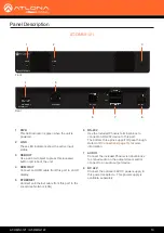
Страница 10: ...connect an RS 232 device to this port The bottom three pins support IR pass through Refer to IR Connections page 14 for more information 7 AUDIO Connect the included Phoenix terminal blocks to embed audio on the output stream and or connect to an audio output device 8 DC 48V Connect the optional 48V DC power supply to this power receptacle This power supply is available separately Panel Descriptio...

Страница 11: ...al Area Network LAN 7 RS 232 Use the included Phoenix terminal block to connect up to two RS 232 devices to this port The RS 232 2 port also supports IR pass through Refer to IR Connections page 14 for more information 8 AUDIO 1 AUDIO 2 Connect the included Phoenix terminal blocks to embed audio on the output stream and or connect to an audio output device 9 DC 48V Connect the optional 48V DC powe...

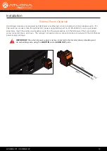
Страница 12: ... separately Insert the positive and negative leads from the power supply into the terminals of the 2 pin captive screw connector block as shown The orange 2 pin captive screw connector block is included with the OmniStream power supply package ETHERNET RS 232 AUDIO OUT IN L R DC 48V RX TX 1 P O S W h i t e B l a c k N E G IMPORTANT The external power supply must be connected to the decoder when em...

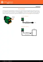
Страница 13: ...at least 3 16 5 mm from the insulation of the RX TX and GND wires 3 Insert the TX RX and GND wires into correct terminal on the included Phoenix block If using non tinned stranded wire press the orange tab above the terminal while inserting the exposed wire Repeat this step for the TX RX and GND connections RS 232 Connections NOTE Typical DB9 connectors use pin 2 for TX pin 3 for RX and pin 5 for ...

Страница 14: ...ee or bottom three set of terminals can be used for IR Only the RS 232 2 port bottom set of connectors supports both RS 232 and IR Therefore this port must be used for IR connections Refer to IR Control page 36 for more information IR emitter configuration IR extender configuration GND black IR emitter SIGNAL white black RX TX GND GND black SIGNAL white black Control Unit TX out GND RX TX GND Inst...

Страница 15: ...nformation Audio Connectors Installation If either the AUDIO IN or AUDIO OUT port will be used then connect the included 5 pin captive screw Phoenix blocks as shown below If both AUDIO IN and AUDIO OUT terminals will be used then connect the included 5 pin push spring Phoenix blocks as shown below 2 channel analog audio input top 2 channel analog audio output bottom ETHERNET RS 232 AUDIO OUT IN L ...

Страница 16: ... terminal while inserting the exposed wire Release the orange tab to lock the wire in place Balanced or unbalanced audio can be used Push tab to unlock Balanced XLR audio Unbalanced XLR audio Unbalanced RCA audio NOTE Unblanaced XLR audio pins require Pin 1 and Pin 3 to be connected IMPORTANT When using analog audio inputs on the OmniStream decoder the decoder must be powered using the 48V power s...

Страница 17: ...to the TX and GND pins of the RS 232 2 port The IR emitter must be placed no more than 1 from the IR sensor on the device in order to function properly IR extender Connect the IR extender from the RX and GND pins of the RS 232 2 port to the associated pins on the control system 6 Once power is applied the PWR indicator on the front panel will turn red then amber then green IMPORTANT If a PoE capab...

Страница 18: ...IS PLA Y INP UT ID 1 2 1 2 1 2 ID PW R LIN K TM OMN ISTRE AM R S 2 3 2 C o n t r o l R S 2 3 2 C o n t r o l Ethernet PoE Ethernet LAN 2 COM NC NO COM NC NO COM NC NO COM NC NO 12V SIG GND 12V SIG GND 12V SIG GND 12V SIG GND 1 COM PON ENT HDM I 1 2 3 4 5 6 SER IAL 1 IR OUT SER IAL 2 L R DIG ITAL COA X OUT AUD IO OUT AUD IO IN ETH ERN ET 2 3 4 VID EO OUT 48V DC FAC TOR Y RES ET ...

Страница 19: ...are set to DHCP mode allowing a DHCP server if present to assign the decoder an IP address Once an IP address has been assigned the Atlona Management System AMS can be used to manage the product on the network Note that AMS will only be able to discover decoders if they are on the same VLAN Accessing Decoders in AMS 1 Launch a web browser and enter the IP address of AMS in the address bar 2 Enter ...

Страница 20: ...laced in Auto IP mode and assigned an IP address within the range of 169 254 xxx xxx If this occurs configure the network interface of the computer that is running AMS located on the same subnet 169 254 xxx xxx subnet mask 255 255 0 0 Refer to the User Manual for more information on configuring a decoder in Auto IP mode If no OmniStream decoders are found then verify the following The computer tha...

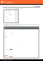
Страница 21: ...figuration 8 Click the desired decoder from the Unassigned device list Once the unit is selected the control interface for the decoder will be displayed The illustration below shows the DEVICE INFO screen for an AT OMNI 122 decoder ...

Страница 22: ...ect an Ethernet cable from the PC directly to one of the Ethernet ports on the decoder Make sure that the computer being used has AMS installed 3 Configure the PC to a static IP address that is on the same subnet as the decoder 4 Login to AMS Refer to Accessing Decoders in AMS page 19 if necessary 5 Locate the decoder under the Unassigned section within AMS 6 Click on the device 7 Under AMS click ...

Страница 23: ...Ethernet cable for possible damage or loose connections Connect the optional 48V DC power supply available from atlona com to the decoder When using an external power supply the PWR indicator will be red Red The decoder is booting Green The decoder is ready LINK 1 2 Red The optional 48V DC power supply is connected but no Ethernet cables are connected between the switch and the ETHERNET port s Che...

Страница 24: ...ces that may be listening 1 Press and hold the ID button for approximately 30 seconds 2 The LED indicators on the front panel will flash then turn off 3 The decoder is now reset and will need to be reconfigured Broadcast Messaging Factory Reset using the Front Panel WARNING Performing a factory default reset will erase all user programmed settings from the decoder IP settings are not preserved Bas...

Страница 25: ...he COM port in the Serial line to connect to field This is the COM port used by the computer to communicate with the OmniStream decoder Refer to Connecting RS 232 to OmniStream page 53 for more information on obtaining the proper COM port 5 Enter the baud rate data bits and stop bits as follows 9600 8 1 6 Click the Parity drop down list and select None Click the Flow control drop down list and sel...

Страница 26: ...A Y INP UT ID 1 2 1 2 HD MI PW R LIN K TM OMN ISTRE AM VO LUM E DIS PLA Y INP UT ID 1 2 1 2 HD MI PW R LIN K TM OMN ISTRE AM VO LUM E DIS PLA Y INP UT ID 1 2 1 2 LAN 192 168 11 116 192 168 11 114 192 168 11 115 192 168 11 117 192 168 11 118 192 168 11 121 1 2 ID PW R LIN K TM OMN ISTRE AM 1 2 ID PW R LIN K TM OMN ISTRE AM 1 2 ID PW R LIN K TM OMN ISTRE AM E n c o d e r E n c o d e r E n c o d e r ...

Страница 27: ... IP INPUT from the menu 7 Remove the IP address from the Multicast Address field 8 Click the SAVE button to commit changes Field should be blank 9 Unicast setup is complete The decoder unit will now receive streams exclusively from the encoder containing the IP address of this decoder ...

Страница 28: ...l be displayed 3 Click the icon in the upper left corner of the AMS Dashboard 4 Click Virtual Matrix from the fly out menu Refer to The Virtual Matrix page 122 if necessary 5 Locate the desired encoder in the Virtual Matrix as shown on the next page 6 Create a cross connection to the desired decoder When a cross connection is created AMS will automatically assign a multicast IP address to both the...

Страница 29: ...AT OMNI 121 AT OMNI 122 29 Basic Operation ...

Страница 30: ... AMS page 19 if necessary 2 Click the HDMI OUTPUT in the menu bar 3 Scroll down to the Video Optimization section and click the Video Optimization drop down list to select the desired mode 4 Click the SAVE button within the Video Optimization section to commit changes Note that switching between video modes may take a few moments to complete 5 Go to the encoder interface and repeat the process Ref...

Страница 31: ...ecoder the presence of the image is specified on the individual HDMI output Refer to the OmniStream Single Channel Dual Channel A V Encoder User Manual for information on managing slate logo insertion on encoder units 1 Login to AMS Refer to Accessing Decoders in AMS page 19 if necessary 2 Click the LOGO tab in the menu bar Slate Logo Insertion Basic Operation 3 Under New logo click the Choose Fil...

Страница 32: ...tio drop down list to set the aspect ratio of the image Selecting Keep will maintain the aspect ratio of the logo source file Selecting Stretch will force the logo to adhere to the user configured settings for the logo size 9 Set the location of the image by entering the desired values in the Horizontal and Vertical fields 10 Define the size of the image by entering the desired values in the Heigh...

Страница 33: ...xt 5 Specify the speed of the scrolling text in the Scroll Speed field Values from 255 to 255 are valid Negative numbers will scroll the text from left to right Positive numbers will scroll text from right to left 6 Enter the number of iterations in the Iteration field Set this field to 0 zero to set the number of iterations to infinity 7 Click the Color drop down list to select the color of the t...

Страница 34: ...NI 122 34 Basic Operation 9 Specify the size of the text in the Width and Height fields Each of these values is based on the horizontal and vertical resolution of the screen 10 Click the SAVE button to apply all changes ...

Страница 35: ...d Number of Channels Resolution Refresh Rate Color Space Bit Depth 1 1920 x 1080p 60 Hz 4 4 4 12 bit 2 1920 x 1080p 30 Hz 4 4 4 12 bit Input Resolution from Encoder Output Resolution AT OMNI 121 Output Resolution AT OMNI 122 1280 x 720p 1280 x 720p 1280 x 720p 1920 x 1080p 60 Hz 1920 x 1080p 60 Hz 1920 x 1080p 30 Hz 1920 x 1080p up to UHD 1920 x 1080p 60 Hz 1920 x 1080p 30 Hz NOTE When fast switch...

Страница 36: ...Controlling the Display using the Display s IR Remote Controlling the Display using a Control System The illustration below shows a display device being controlled from the encoder Refer to the next page for details on how to connect the IR emitter and IR receiver Controlling the Display using the Display s IR Remote AT OMNI 111 Network Switch AT OMNI 121 IR Remote E t h e r n e t E t h e r n e t ...

Страница 37: ... screwdriver and connect the SIGNAL GROUND and POWER leads of the AT IR CS RX to the Xantech 789 44 4 Source Connecting Block as shown below The presence or absence of white markings on each wire of the AT IR CS RX will denote the signal type IR IN Dashed dark gray line GND Solid no marking black wire 12 VDC solid dark gray line Connecting the IR Receiver to the Encoder E M I T T E R S IR IN STATU...

Страница 38: ...the illustration below for purposes of clarity Connecting the IR Emitter to the Decoder 1 Connect the included 6 pin Phoenix connector to the RS 232 2 port on the encoder 2 Connect the SIGNAL wire of the AT OMNI IR TX to the TX middle terminal on the RS 232 2 port 3 Connect the GROUND wire of the AT OMNI IR TX to the terminal on the RS 232 2 port 2 Connect the IR IN and GND leads from the 789 44 4...

Страница 39: ...he AMS Dashboard will be displayed 5 Click the icon in the upper left corner of the AMS Dashboard 6 Click Devices from the fly out menu 7 Click the All option 8 Click the desired encoder within the AMS Device List window The AMS interface for the encoder will be displayed 9 Locate and make note of the IP address of the encoder which can be found in the IP Address field If using dual channel encode...

Страница 40: ... Serial page of the encoder web interface 1 Enter the IP address of the encoder in the address bar of the web browser 2 Enter the required login credentials The default login is Username admin Password Atlona 3 Click the Login button 4 Click Serial in the top menu bar SAVE button 5 Locate the Serial port configuration window group The Name field within this window group should read serial_port2 Cl...

Страница 41: ...lso be used with IR However in this example Session 1 will be configured 1 Click SESSION in the top menu bar 2 Locate the Session 1 window group Configuring the Encoder Session The next step is to assign the IR control for Serial Port 2 to the desired Session ...

Страница 42: ...y clicking the Enable toggle switch When the auxiliary channel is enabled this toggle switch will be orange 6 Enter the IP address of the decoder in the Destination IP Address field This is the decoder to which the IR emitter is connected In this example the decoder IP address is 10 20 200 141 7 Enter the port number in the Destination UDP Port field 8 Click the SAVE button to commit changes ...

Страница 43: ... 5 by clicking the Enable toggle switch When enabled this toggle switch will be orange 6 Enter the port in the Port field This port number must be the same port used by the encoder and is the input of the decoder that will receive IR data NOTE Input 5 is dedicated to IR Therefore this input must be used in order for end to end IR to function properly Enable SAVE button IMPORTANT Do not change the ...

Страница 44: ...port2 Click the Modes drop down list and select Infrared 10 Click the SAVE button to commit changes 11 Scroll down the page and locate the Serial Configuration window group The Name field within this group should read serial_use2 12 Click the Port drop down list and select serial_port2 13 Click the Mode drop down list and select output 14 Click the Input drop down list and select ip_input5 ...

Страница 45: ...AT OMNI 121 AT OMNI 122 45 IR Control 15 Click the SAVE button to commit changes ...

Страница 46: ... OMNISTREAM IMPORTANT The IR lens of the emitter must be within 1 inch 2 54 centimeters of the IR window on the display device If this distance is exceeded then IR functionality may fail 1 Point IR remote to at the IR Receiver as shown in the diagram below 2 The IR remote will now sent IR data to the decoder where it will be relayed to the display device ...

Страница 47: ...g should be used instead of an IR receiver as shown below AT OMNI 111 Network Switch AT OMNI 121 Control System Ethernet Ethernet H D M I IR HDMI Display IR Emitter HD MI PW R LIN K TM OMN ISTR EA M VO LU ME DIS PLA Y INP UT ID 1 2 1 2 1 2 ID PW R LIN K TM OMN ISTR EA M IR Signal Blu ray Player Auto mat ion Con trol Sys tem Controlling the Display using a Control System ...

Страница 48: ...Using the Virtual Matrix 1 Login to AMS Refer to Accessing Decoders in AMS page 19 if necessary 2 Click the icon in the upper left corner of the AMS Dashboard 3 Click on Virtual Matrix 4 The OmniStream Virtual Matrix page will be displayed ...

Страница 49: ...t and select Control IR Control 6 The Control screen will be displayed In the Control screen HDMI ports are replaced with control ports Port 1 In Port 1 In for encoders and Port 1 Out Port 2 Out for decoders 7 Click the Options button next to the desired decoder ...

Страница 50: ...erial Port 2 supports IR pass through The IR emitter or IR receiver must be connected to this port Refer to IR Connections page 14 for wiring information 10 Click SAVE to commit changes then click CLOSE to dismiss the dialog and return to the Virtual Matrix page To return to the Virtual Matrix page without saving changes click the CLOSE button to dismiss the dialog ...

Страница 51: ...e AUDIO OUT ports Refer to Audio Connectors page 15 for wiring information 3 Login to AMS Refer to Accessing Decoders in AMS page 19 if necessary 4 Select the decoder in AMS 5 Click HDMI OUTPUT in the menu bar 6 Scroll down to the Audio section 7 Click the Analog Output toggle switch to enable it When enabled the toggle switch will be green Also note that the Analog Output Power indicator above th...

Страница 52: ...rs Refer to Audio Connectors page 15 for wiring information 3 Login to AMS Refer to Accessing Decoders in AMS page 19 if necessary 4 Select the decoder in AMS 5 Click HDMI OUTPUT in the menu bar 6 Scroll down to the Audio section 7 Click the Analog Input toggle switch to enable it When enabled the toggle switch will be green Also note that the Analog Input Power indicator above the toggle switch w...

Страница 53: ...rial port on the computer which is being used to connect to the OmniStream device 2 Verify that the driver is properly installed by launching Windows Device Manager Press keys simultaneously then click Device Manager from the menu X 3 Locate the Ports section within the Device Manager window and verify that the driver has assigned a COM port for the USB cable In the example above COM1 was created ...

Страница 54: ...site end of the cable When the wire connected to that pin is detected the multimeter will emit an audible tone Once this occurs identify the current wire by moving it to the side 8 Repeat step 6 for pin 3 and pin 2 on the USB connector 9 Group the remaining wires and pull them aside Electrical tape can be use to secure the wires to the outside of the USB cable The following illustration shows the ...

Страница 55: ...n then click the SAVE button 8 Scroll down to the Command sections Each section is labeled for the command type 9 Click the Mode drop down list and select the Decoder option 10 Enter the associated command in the ASCII or HEX fields then click the SAVE button Refer to the User Manual for the sink device for the list of available commands 11 Repeat steps 8 10 for each command as desired Trigger the...

Страница 56: ...t section for the connected device then click the SAVE button 5 Scroll down to the Serial Configuration section 6 Click the Port drop down list and select the desired serial port 7 Click the Mode drop down list and select the tcpproxy option then click the SAVE button 8 Click the Interface drop down list to select the interface Ethernet port that will be used to transmit the data 9 Click the Mode ...

Страница 57: ...ion Using the Virtual Matrix 1 Login to AMS Refer to Accessing Decoders in AMS page 19 if necessary 2 Click the icon in the upper left corner of the AMS Dashboard 3 Click on Virtual Matrix 4 The OmniStream Virtual Matrix page will be displayed ...

Страница 58: ...d select Control Advanced Operation 6 The Control screen will be displayed In the Control screen HDMI ports are replaced with control ports Port 1 In Port 1 In for encoders and Port 1 Out Port 2 Out for decoders 7 Click the Options button next to the desired decoder ...

Страница 59: ...y RS232 Passthrough is available from drop down list When the ADVANCED option is enabled the following modes will be available Refer to the list of modes on the right hand side of the dialog for a description of each Each of these configurations will be covered in the following pages RS232 Passthrough Serial over IP Proxy TCP Proxy RS232 Trigger 8 The Crosspoint Options dialog will be displayed ...

Страница 60: ... to the decoder The RS 232 commands are then received by a display DCE device or other sink device 1 Select RS232 Passthrough from the Serial Mode drop down list 2 Click SAVE to commit changes then click CLOSE to dismiss the dialog and return to the Virtual Matrix page To return to the Virtual Matrix page without saving changes click the CLOSE button to dismiss the dialog ...

Страница 61: ...de the required settings These settings must match the port settings on the display sink device a Click the Interface drop down list to select the interface Ethernet port that will be used to transmit the data b Enter the port number in the TCP Proxy Port field This number can be in the range from 0 to 65535 c Specify the baud rate data bit parity stop bit and flow control is the appropriate field...

Страница 62: ... Hex command string 3 Scroll down to the Serial Port settings and provide the required baud rate data bit parity stop bit and flow control settings These settings must match the port settings for the display sink device 4 Click SAVE to commit changes then click CLOSE to dismiss the dialog and return to the Virtual Matrix page To return to the Virtual Matrix page without saving changes click the CL...

Страница 63: ...al Matrix page 2 Locate the desired encoder and decoder where the cross connection will be created In the following example Port 1 In and Port 1 Out on the AT OMNI 112 and AT OMNI 122 in the upper left corner of the Virtual Matrix will be selected 3 Click the icon to create the cross connection Once a cross connection is created it will be represented by a C in a purple circle as shown below To re...

Страница 64: ...OmniStream encoder and decoder Ethernet EAPOL EAP EAP Ethernet RADIUS Ethernet Normal traffic Supplicant Encoder or Decoder Authenticator Switch Extensible Authentication Protocol Authentication Server LAN HD MI PW R LIN K TM OMN ISTRE AM VO LUM E DIS PLA Y INP UT ID 1 2 1 2 Protocol Description none 802 1X protocol disabled PEAP MSCHAPv2 Protected EAP requires basic credentials in addition to a CA ...

Страница 65: ...left corner of the AMS Dashboard 4 Click Devices All and select the desired decoder from the Device List 5 Click NETWORK in the menu bar 6 Click the 802 1x Mode drop down list at the bottom of the page and select PEAP MSCHAPv2 7 Three additional fields will be displayed Identify Password and CA certificate Provide the required information in each field Refer to the illustration on the next page if...

Страница 66: ... 122 66 Advanced Operation 8 Click the SAVE button near the bottom of the page If using dual channel decoders both Network 1 and Network 2 both Ethernet ports will need to be set up depending upon the system requirements ...

Страница 67: ...r of the AMS Dashboard 4 Click Devices All and select the desired decoder from the Device List 5 Click NETWORK in the menu bar 6 Click the 802 1x Mode drop down list at the bottom of the page and select EAP TLS 7 Three additional fields will be displayed Client certificate Client private key and CA certificate Provide the required information in each field Refer to the illustration on the next pag...

Страница 68: ... 122 68 Advanced Operation 8 Click the SAVE button near the bottom of the page If using dual channel decoders both Network 1 and Network 2 both Ethernet ports will need to be set up depending upon the system requirements ...

Страница 69: ...67 toggle switch Session 1 1 Login to AMS Refer to Accessing Decoders in AMS page 19 if necessary 2 The AMS Dashboard will be displayed 3 Click the icon in the upper left corner of the AMS Dashboard 4 Click Devices All and select the desired encoder from the Device List 5 Go to the encoder interface and click SESSION in the menu bar Refer to the OmniStream Single Channel Dual Channel A V Encoder U...

Страница 70: ...r Mono 8 Click the SAVE button within the Session section 9 Go to the decoder interface and click SAP from the menu bar at the top of the screen Under the SAP section click the Enable toggle switch and enable SAP When enabled the toggle switch will be green If the decoder is to receive AES67 audio this step is required 10 Click the SAVE button on the SAP page ...

Страница 71: ...e the desired encoder and decoder where the cross connection will be created In the following example Port 2 In and Port 2 Out on the AT OMNI 112 and AT OMNI 122 in the upper left corner of the Virtual Matrix will be selected 3 Click the icon to create the cross connection Once a cross connection is created it will be represented by a C in a purple circle as shown below To remove the cross connect...

Страница 72: ... Data streams cannot be scrambled only video and audio can be scrambled When scrambled information is received from an encoder it will need to be descrambled before it can be displayed When scrambling is enabled the scrambling key can be found under the HDMI OUTPUT page on the decoder Scrambling 1 Click HDMI OUTPUT in the menu bar 2 Under the desired Session click the Enabled toggle switch next to...

Страница 73: ...es are not permitted Using the Virtual Matrix 1 Access the Virtual Matrix Refer to The Virtual Matrix page 122 for more information 2 Locate the desired encoder or decoder Scrambling is handled on the encoder descrambling is handled on the decoder 3 Click the yellow key icon The Scrambling dialog box will be displayed If the key icon for a decoder is clicked then the Descrambling dialog box will b...

Страница 74: ... one of the following methods Manual enter a user defined key in the Key field 6 Repeat the above process for each session 7 Click the Save button to commit the changes Click the icon to generate a random key using AMS Each time this icon is clicked a new scrambling key will be generated ...

Страница 75: ...U T ID 1 2 1 2 1 2 ID PWR LINK TM OMNI STREA M 1 2 ID PWR LINK TM OMNI STREA M 1 2 ID PWR LINK TM OMNI STREA M 1 2 ID PWR LINK TM OMNI STREA M LAN Encoder Decoder Decoder Decoder Decoder 1 1 3 2 4 3 2 4 Advanced Operation Resolution Maximum Video Wall Size 4Kp60 2 x 2 4Kp30 16 x 16 1080p60 n x n no limit NOTE OmniStream video walls do not support 1080i sources This diagram presents some challenges...

Страница 76: ...ich each image is cropped scaled and or rotated is arbitrary In this example the configuration process will begin with Display 1 in the top left 1 Login to AMS Refer to Accessing Decoders in AMS page 19 if necessary 2 Click HDMI OUTPUT in the menu bar 3 Locate the Resolution option in the Video section and select 1920x1080 This will scale the output resolution from each decoder to 1920x1080 ...

Страница 77: ...esolution Width Height 3840 x 2160 UHD 1920 1080 1920 x 1080 1080p 960 540 7 Enter the horizontal and vertical resolution of the display in the Width and Height fields This is the size of the source to be used for this window of the video wall The table below lists width and height examples for a 2x2 video wall with the specified source resolution IMPORTANT When using Millimeters or Inches two add...

Страница 78: ...60 UHD 0 0 1920 0 0 1080 1920 1080 1920 x 1080 1080p 0 0 960 0 0 540 960 540 9 Click the Rotation drop down list to select the rotation angle of the image In this example select 180 from the drop down list The image will be flipped vertically This step is only applied when configuring the two top displays Advanced Operation NOTE When using dual channel decoders the Rotation feature can only be use...

Страница 79: ... Repeat steps 1 through 9 for decoders 2 3 and 4 Note that in this example at Step 9 decoders 3 and 4 will not require any rotation Therefore make sure the Rotation option is set to 0 for decoders 3 and 4 Display Wall HDM I PWR LINK TM OMNI STREA M VOL UME DISP LAY INPU T ID 1 2 1 2 1 2 ID PWR LINK TM OMNI STREA M 1 2 ID PWR LINK TM OMNI STREA M 1 2 ID PWR LINK TM OMNI STREA M 1 2 ID PWR LINK TM O...

Страница 80: ...oder Decoder Decoder Decoder Decoder 1 3 2 4 1 3 2 4 Once all four decoders have been properly configured the image will be correctly displayed across all four displays 12 Check the image on each display and make sure they are aligned correctly with the other images on the video wall Use the Edge Compensation drop down list to adjust bevel compensation if necessary Refer to Bezel Compensation page...

Страница 81: ...ows a simple 2x2 video wall without bezel compensation Note how the Atlona logo appears stretched horizontally On the right bezel compensation is used to correct the image 1 Select Bezel Compensation from the Edge Compensation drop down list 2 Enter the Top Bottom Left and Right values as desired Values can be entered in pixels inches or millimeters 3 Click the SAVE button at the bottom of the scr...

Страница 82: ...n button 4 The Velocity Dashboard will be displayed 5 Click the icon in the upper left corner to display the fly out menu Click to display fly out menu 6 Click Sites in the menu bar to expand the list of buildings and rooms 7 Click the desired room from the list In the example on the right a set of encoders and decoders have been set up in the Bar Restaurant room of Building 1 This is where the vi...

Страница 83: ...con in the top far right corner of the screen This icon is represented by the sign 9 The Technology fly out menu will be displayed 10 Click Miscellaneous Atlona to expand the Atlona technology menu 11 Click the Add button for Velocity Video Wall VELOCITY VIDEO WALL The video wall technology will be added to the room ...

Страница 84: ...lly be displayed when the video wall driver is edited for the first time The default video wall dimensions are set to 3840 x 2160 To modify the video wall size follow steps 14a through 14e To continue with the default video wall dimensions click the CLOSE button and go to step 15 a Click the Lock Pixel Space toggle switch to disable it When disabled the toggle switch will turn gray b Under Pixel S...

Страница 85: ... l a Displays Click to icon to show the Displays window on the left side of the screen In this mode displays can be edited b Presets Click this icon to display the Presets window on the left side of the screen In this mode presets can be edited added or deleted c Drop Zones Click this icon to display the Drop Zones window on the left side of the screen Refer to Creating and Using Drop Zones page 9...

Страница 86: ...lider to adjust the zoom factor of the Pixel Space window i Apply Preset Click this icon to apply the current preset Click the down arrow next to this icon to display the Apply Preset fly out menu This control defines when Velocity automatically applies a preset 1 Auto apply preset on save 2 Auto apply preset on source change j Save Click this icon to save the current layout settings Click the dow...

Страница 87: ...ion In this example a 2x2 video wall will be created Once Auto Arrange has been applied the Pixel Space window will appear similar to the illustration below It should be noted that each display can be rearranged if necessary To reposition displays click and drag them to the appropriate places within the Pixel Space window Note that each display is identified with a name and an IP address in the up...

Страница 88: ...is icon will turn red Both the Trash and Auto Arrange icons will be disabled To unlock the displays for adjustment purposes click the Lock Displays icon again 19 Click the Save icon in the upper right corner of the Pixel Space window This will save the current layout 20 Click the Presets icon When clicked this icon will turn green and the Presets window will be displayed on the left side of the sc...

Страница 89: ...e can be mapped to each display For example in the illustration below the AT OMNI 512 225 0 0 19 port 1000 has been mapped to both Left Display 2 upper left corner and Left Display 1 lower right corner Sources can also be re sized on the fly to achieve the desired presentation Refer to the illustration on the next page To re size a source click and drag the source window horizontally vertically or...

Страница 90: ...upy fractions of a display window 25 Click ADD under the Presets section on the left side of the screen to create additional presets 26 Repeat steps 21 through 23 to create the preset Once the desired presets have been created click the preset name under the Presets section to recall it The video wall will be updated with the selected preset Refer to the Atlona Velocity User Manual for more inform...

Страница 91: ...on the fly within the Video Wall Control Screen 1 Populate the Pixel Space window with the desired devices 2 Click the Lock Displays icon to lock the devices in place 3 Click the Drop Zones icon in the Pixel Space menu bar 4 Click ADD under the Drop Zones window on the left side of the screen This will create the Drop Zone preset 5 Click EDIT and provide a name for the Drop Zone in the Drop Zone E...

Страница 92: ... in the Edit Zone dialog box Click Close to save the change Note that each time the ADD button is clicked a new Drop Zone container is created In this first example two Drop Zone containers are created When adding containers note that the position of each container is created in the same position within the Pixel Space window ...

Страница 93: ...tainer is positioned over the intersection of two windows then it will automatically be resized to accommodate both devices as shown below If placed over the corner intersection of more than two windows then the container will be resized to cover all devices occupying that space Window Intersection Container automatically resized 10 Click the Lock Preset button one the containers have been placed ...

Страница 94: ...However the number of containers that are created should not exceed the number of devices within the Pixel Space window 12 Click the Save icon to commit all changes 13 Close the Video Wall Configuration window by clicking the X in the upper left corner of the screen 14 Click the Launch Control icon in the far left corner of the Modify Room screen 15 Click the VIDEO WALL icon ...

Страница 95: ...screen to access the Drop Zones which were created earlier In the example example below two Drop Zones were created Created Zones The first Drop Zone that was created shows two containers on the left and a single container on the right The second Drop Zone only uses two containers one on the top and one on the bottom The Preset which we created is a 2x2 video wall and represents the physical layou...

Страница 96: ...combinations are shown below Drop Zone containers have been labeled alphabetically for reference Note that although the top right and bottom right displays are physically separate dragging and dropping a source from the left hand side of the screen to Drop Zone container C will map the source to both displays To change to a different source drag and drop a source from the left hand side of the scr...

Страница 97: ...the decoders 1 Return to the Video Wall Configuration screen and click the Pixel Space icon in the Pixel Space menu bar Pixel Space icon Allow custom drop zone 2 Click the Allow custom drop zone toggle switch to enable it When enabled this toggle switch will be green 3 Click CLOSE to save changes and dismiss the dialog box 4 Click the Save icon in the top right portion of the Video Wall Configurat...

Страница 98: ...ck the Launch Control icon on the Modify Room screen 6 Click the VIDEO WALL icon to enter video wall control screen 7 Click Zones at the bottom of the screen then click the Custom Drop Zone icon Custom Drop Zone 8 Drag and drop sources from the left side of the screen as performed with normal Drop Zones ...

Страница 99: ...e desired area of a container To reposition the source to a different container s click in the middle of a source then drag and drop to the desired container s If the source is dropped at the intersection of two containers the source will automatically be resized to fill both containers In the example below the source will be displayed on all four screens ...

Страница 100: ...rosspoint Options dialog box will be displayed Advanced Operation Configuring Redundant Streams 4 Select the backup mode for Video Redundancy and or Audio Redundancy from the Backup Mode drop down lists Refer to the table below for a listing and description of the available modes Switching time will be dependent upon the network switch that is used as well as the number of hops between encoders an...

Страница 101: ... redundancy is enabled a grace period can be entered By default the grace period is set to 0 seconds If set to 0 seconds automatic failover will occur if the stream is interrupted for any reason Refer to Configuring Redundant Streams page 54 for more information on enabling or disabling redundancy 3 Locate the Change grace period field 4 Enter the desired value in seconds By default this value is ...

Страница 102: ...o page The Device Info page provides general information about the decoder Alias Enter a name for the unit in this field This is optional Model The model number of the unit Model Description AT OMNI 121 Single channel decoder AT OMNI 122 Dual channel decoder ...

Страница 103: ...ostname The hostname of this unit This can be changed if desired By default the host name is automatically created using the model of the unit and adding the last five digits of the unit serial number NTP Server Specify the desired NTP server in this field This provides timestamps for any logs and alarms Buttons Disabling this feature will lock the ID button on the front panel This is enabled by d...

Страница 104: ...ured This option can be used to configure a single encoder to transmit to any number of decoders without using the Virtual Matrix within AMS NOTE This will not work for multiple encoders on the same network IMPORT CONFIGURATION Click this button to upload the configuration file to the decoder FACTORY RESET Click this button to reset the decoder to factory default settings When performing a factory...

Страница 105: ...otocol Enabling SAP configures the decoder to look for SAP messages from decoders on the network that are configured to send SAP Any messages that are discovered will be displayed here Enabled Click this toggle switch to enable or disable SAP If enabled the toggle switch will be green Click the SAVE button to commit changes ...

Страница 106: ...MS to identify the IP input Enable Click this checkbox to enable the IP input Interface Select the physical interface that will be used to carry the multicast traffic from this drop down list When using a single channel decoder only eth1 will be available Multicast Address Enter the multicast address of the decoder stream Input Description eth1 ETHERNET 1 port eth2 ETHERNET 2 port ...

Страница 107: ...ce Mode Click this drop down list to select the mode Mode can be set to exclude or include and is specifically used when using Source Specific Multicast SSM SSM will only function if the network is properly set up to support it Addresses Enter the IPv4 address of the encoder s in this field and is used as the SSM include exclude list Use the comma delimiter to separate multiple IP addresses When u...

Страница 108: ...characters Special characters and spaces are not permitted Encrypted Indicates if the content is HDCP encrypted or not If true then HDCP content is being passed in to the decoder and this indicator will be colored green Supported Version Click this drop down list to select the desired HDCP version If set to none then the sink is reported as non compliant and will receive non HDCP content Input Des...

Страница 109: ...s for switching inputs Configuration Grace Period To prevent the decoder from automatically making the redundancy switch when redundancy is enabled a grace period can be entered By default the grace period is set to zero seconds If set to zero seconds automatic failover will occur if the stream is interrupted for any reason Refer to Configuring Redundant Streams page 100 for more information Activ...

Страница 110: ...all Enable Click this toggle switch to enable or disable the video wall feature When enabled the toggle switch will be green Refer to Creating Video Walls page 75 for more information Fast Switching Enable Click this toggle switch to enable or disable fast switching Refer to Fast Switching page 35 for more information To Primary Click this button to make the video use the Primary IP Input To Backu...

Страница 111: ...audio type If no audio is present then this field will display No active audio Mute Click this toggle switch to enable or disable the audio output If enabled the toggle switch will be green Volume Click the speaker icon on the left to decrease volume Click the speaker icon on the right to increase volume Range 0 to 15 Analog Input If analog input is connected to the decoder then click this toggle ...

Страница 112: ...e Description DispSW AVon Display switches on off source audio video signal always on DispSW AVSW Display switches on off source audio video signal switches on off AV SW Display is always on source audio video signal switches on off Always on Display is always on source audio video signal always on Aux CEC Video Optimization Sets the video mode to optimize the output for motion video or computer g...

Страница 113: ...red baud rate Data Click this drop down list to select the number of data bits Parity Click this drop down list to select the parity bit Stop Click this drop down list to select the stop bit Flow Click this drop down list to select the type of flow control Serial page The Serial Config tab provides serial port configuration when using control signals The AMS Interface NOTE The single channel decod...

Страница 114: ...ch to enable bidirectional serial communication When enabled the toggle switch will be green The AMS Interface Interface Description eth1 ETHERNET 1 port eth2 ETHERNET 2 port Interface Description cli Displays the command line interface of the decoder Output Serial port will send commands directly to the display device tcpproxy Commands are sent over IP but triggered over the serial port NOTE The ...

Страница 115: ...eted ASCII Enter the ASCII representation of the command string in this field HEX Enter the hexadecimal representation of the command in this field Interpret on Description Raw Commands are interpreted at the encoder decoder Commands are interpreted at the decoder NOTE When entering the command string it is not required to enter the string under both the ASCII and HEX fields The decoder requires t...

Страница 116: ...le the text When the toggle switch is green the text will be enabled Text Enter the desired text in this field Scroll Speed Enter the scrolling speed in this field Values from 255 to 255 are valid Negative numbers will scroll the text from left to right Positive numbers will scroll text from right to left Iterations Enter the number of iterations in the Iteration field Set this field to 0 zero to ...

Страница 117: ... and a value of 0 is transparent Numbers from 0 to 255 are valid for each of these fields Horizontal Vertical Specify the location of the text in the Horizontal and Vertical fields Each of these values is based on the horizontal and vertical resolution of the screen Width Height Specify the size of the text in the Width and Height fields Each of these values is based on the horizontal and vertical...

Страница 118: ... Slate Logo Insertion page 31 for more information on using logos Name Enter a name for the logo in this field Choose File Click this button to select the logo file to be uploaded Files must be in png format and must not exceed 5 MB 5210000 bytes in size When an image file is uploaded it will appear in the Logo drop down list UPLOAD Click this button to upload the logo file to the decoder New Logo...

Страница 119: ...oaded then this will be set to Not Used Aspect Ratio Click this drop down list to select the type of aspect ratio to be applied to the logo Horizontal Enter the horizontal position of the logo on the screen Vertical Enter the vertical position of the logo on the screen Height Enter the horizontal resolution of the logo in pixels Width Enter the vertical resolution of the logo in pixels NOTE Maximu...

Страница 120: ...in this field Valid entries are 0 through 127 Priority 1 Enter the priority number in this field Priority 2 Enter the priority number in this field Is GM Present This indicator displays the existence of a grandmaster clock for the specified PTP domain number If the indicator is green then the grandmaster clock exists on this interface GM Identity The grandmaster clock identity If this field is bla...

Страница 121: ...e DHCP server if present assign the decoder the IP settings Subnet and Gateway fields will automatically be populated When Static mode is selected the information for the IP Address Subnet and Gateway fields must be entered IP Address Displays the IP address used by the channel This field can only be changed if Static mode is selected Subnet Displays the subnet mask for the channel This field can ...

Страница 122: ... OMNI 121 AT OMNI 122 122 1 Click the icon in the upper left corner of the AMS Dashboard 2 Click Virtual Matrix 3 The OmniStream Virtual Matrix page will be displayed The Virtual Matrix The AMS Interface ...

Страница 123: ...ill be displayed on HDMI 1 on the decoder This will create a cross connection which connects both the encoder and decoder together Creating a cross connection To route an input on an encoder to an output locate the row and column where an input and output intersect then click the square with the dots around it Removing a cross connection To remove a cross connection click on the desired circle ico...

Страница 124: ...yed as a dark blue circle with the letter D The icons in the upper left corner can also act as a filter This allows for a clear breakdown of where signals are being routed and is useful when several encoders and decoders are used on a network Symbol Description Video only Audio only Data only Connected not all signals are active Connected all streams are being used V A D IMPORTANT R Type and Pro c...

Страница 125: ...ately 1 to 2 minutes For full functionality of OMNI 1 2 1 or later Velocity must be running at least 1 4 5 and AMS must be on firmware version 2 0 12 and above 1 Click DEVICE INFO in the menu bar 2 Click the UPDATE FIRMWARE button to display the Firmware Update dialog Drag firmware file here Uploaded firmware file 3 Click and drag the firmware file to the yellow box to upload the firmware to the d...

Страница 126: ...ndicates that a firmware update is in progress The progress bar for the update process will be displayed The update process should take a few seconds 7 Click the X to close out the progress bar window then click the CLOSE button to dismiss the Firmware Update message box 8 The firmware update process is complete 9 Clear the web browser cache and refresh the web page The new firmware version will a...

Страница 127: ...Dolby Vision Licensing Identify the license type from the table below 1 Login to AMS Refer to Accessing Decoders in AMS page 19 if necessary 2 Select the desired OmniStream decoder from the list of devices The DEVICE INFO screen will be displayed 3 Scroll down and identify the Dolby Vision License Key field Products Purchased with Dolby Vision SKU Product Application License Notes AT OMNI DEC DV1 ...

Страница 128: ...02ab3070ca787f030 NOTE If the Dolby Vision license for both channels dual channel units only was purchased then the email will contain two separate licenses DOLBYVISION1 and DOLBYVISION2 6 Click the SAVE LICENSE button to commit changes Once the license key is accepted the Dolby Vision License Enabled indicator will turn green and the SAVE LICENSE button will be hidden as shown below 7 A pop up me...

Страница 129: ...dress of the decoder The request code will look similar to the following DOLBYVISION1 c8afb021acf9 Activating Dolby Vision on Deployed Decoders Request code Appendix 5 Send the request code along with a purchase order PO to one of the following email addresses Contact Location domesticorders atlona com United States internationalorders atlona com Outside the United States NOTE Request codes corres...

Страница 130: ...e license key For example DOLBYVISION1 28fd7802ab3070ca787f030 8 Click the SAVE LICENSE button to commit changes Once the license key is accepted the Dolby Vision License Enabled indicator will turn green and the SAVE LICENSE button will be hidden as shown below License key 9 A pop up message will be displayed at the bottom of the screen prompting a reboot Reboot the OmniStream decoder by clicking...

Страница 131: ...s tight as possible FEC latency overhead is also inversely proportional to bitrate the higher the bitrate the less FEC latency is introduced For applications where lip sync is very critical using a higher audio sampling rate and thus a higher audio bitrate can result in more accurate lip sync The bitrate configured on the video encoder includes FEC overhead and will automatically adjust itself dep...

Страница 132: ...arious matrix sizes It is recommended to keep lip sync within 1 frame of video to prevent any noticeable syncing issues Examples of good choices to minimize lip sync issues are Video configured for 450 Mbps FEC 10x10 Audio is 2 channel PCM 192 kHz FEC 1x4 6 40 ms 7 81 ms 1 41 ms Video configured for 900 Mbps FEC 10x10 Audio is 2 channel PCM 48 kHz FEC disabled 6 40 ms 0 ms 6 40 ms Audio additional...

Страница 133: ...nclosure 4 To provide added stability to the rack ear use two of the included screws and attach them to the two holes directly below the enclosure screws as shown above 5 Repeat steps 1 through 4 to attach the second rack ear to the opposite side of the unit 6 Mount the unit using the oval shaped holes on each rack ear If using a drywall surface a 6 drywall screw is recommended HDMI PWR LINK TM OM...

Страница 134: ...nient 1U rack tray The OmniStream rack tray can be purchased directly from Atlona 1 Position the OmniStream products as shown in the illustration below 2 Using the included screws secure each unit to the rack with a Philips screwdriver 3 Install the entire assembly into an empty 1U slot in the rack HDMI PWR LINK TM OMNISTREAM VOLUME DISPLAY INPUT ID 1 2 1 2 TM OMNISTREAM LINK PWR NOTE OmniStream u...

Страница 135: ...0 dB THD N 0 03 at 20 Hz to 20 kHz SNR 90 dB at 1 kHz zero clipping 0 dBFS unweighted Decoding Density One decoding engine Decoding Format VC 2 SMPTE 2042 Chroma Subsampling 4 4 4 4 2 2 4 2 0 Video Quality Optimization User selectable Computer Graphics or Motion Video Color Depth 8 bit 10 bit 12 bit HDR HDR10 HLG Dolby Vision 4 Bit Rate Supports bit rates up to 900 Mbps Latency 0 5 frame e g 1080p...

Страница 136: ...only AUDIO 1 Euroblock 10 pin AUDIO IN OUT accepts balanced or unbalanced line Power 1 Euroblock 2 pin Control CEC Supported and triggered from control systems and OmniStream encoders RS 232 Device control and configuration supports baud rates from 2400 to 115200 Bidirectional pass through from control system to network Bidirectional TCP Proxy RS 232 commands over IP IR Pass through from control s...

Страница 137: ...0 03 at 20 Hz to 20 kHz SNR 90 dB at 1 kHz zero clipping 0 dBFS unweighted Decoding Density Two decoding engines Decoding Format VC 2 SMPTE 2042 Chroma Subsampling 4 4 4 4 2 2 4 2 0 Video Quality Optimization User selectable Computer Graphics or Motion Video Color Depth 8 bit 10 bit 12 bit HDR HDR10 HLG Dolby Vision 4 Bit Rate Supports bit rates up to 900 Mbps Latency 0 5 frame e g 1080p 60 Hz lat...

Страница 138: ... IN OUT AUDIO 2 IN OUT accepts balanced or unbalanced line Power 1 Euroblock 2 pin Control CEC Supported and triggered from control systems and OmniStream encoders RS 232 Device control and configuration supports baud rates from 2400 to 115200 Bidirectional pass through from control system to network Bidirectional TCP Proxy RS 232 commands over IP IR Pass through from control system to network Pas...

Страница 139: ...d names and trademarks or registered trademarks are the property of their respective owners Pricing specifications and availability subject to change without notice Actual products product images and online product images may vary from images shown here Toll free US International atlona com 877 536 3976 41 43 508 4321 ...

Отзывы: