background image

AT-UHD-CAT-8

14

Basic Operation

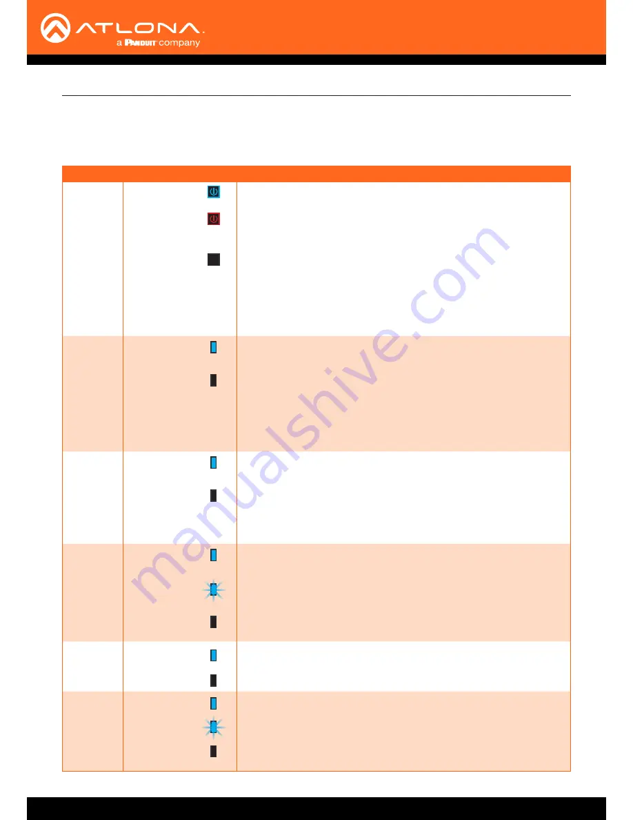
The LED indicators on both the front of the unit provide basic information on the current status of the AT-UHD-CAT-8.

LED Indicators

LED

Description

POWER

Blue

Unit is powered and in normal operating mode.

Red

Unit is in standby mode.

• 

Press the 

POWER

 button to place the unit in normal operating mode.


Off

Unit is not powered.
•  Check the power supply and make sure it is securely fastened to the 

locking connector on the rear of the unit.

• 

Make sure that the power supply is connected to an available 

electrical outlet and that the outlet is “live” (some outlets are controlled 

by a wall switch).

HDMI 

IN / OUT

Blue

IN:  Source is connected to the 

HDMI IN

 port. 

OUT: Sink device is connected to the 

HDMI OUT

 port.

Off

IN:  No source device connected to the 

HDMI IN

 port. 

OUT: No sink device is connected to the 

HDMI OUT

 port.

• 

Check the integrity of the HDMI cable; make sure a secure connection 

exists between the HDMI port on the AT-UHD-CAT-8 and the source/

display device.

• 

Try a different HDMI cable.

HDBaseT


1 - 8

Blue

Normal operation.  Signal integrity between the AT-UHD-CAT-8 and the 

connected receiver is good.

Off

No connection between the HDBaseT port on the AT-UHD-CAT-8 and the 

receiver unit.
• 

Check the Ethernet cable for a secure connection.

• 

Possible bad cable; try a different Ethernet cable.

LOCK

Blue

Front-panel buttons on the AT-UHD-CAT-8 are locked.  Refer to the API or 

Locking the Front Panel (page 15)

 for more information. 

Flashing Blue

The number of flashes indicate whether the unit is in DHCP or static IP 

mode.  Refer to 

IP Configuration (page 12)

 for more information.

Off

Front-panel buttons on the AT-UHD-CAT-8 are unlocked.

INT

Blue

AT-UHD-CAT-8 is using the internal EDID.  Refer to 

EDID Management 

(page 16)

 for more information on INT EDID mode.

Off

AT-UHD-CAT-8 is set LEARN EDID mode.

LEARN

Blue

AT-UHD-CAT-8 is in “learn” mode.  Refer to 

EDID Management (page 

16)

 for more information on LEARN EDID mode.

Flashing Blue

AT-UHD-CAT-8 is in the process of learning the downstream EDID.

Off

AT-UHD-CAT-8 is set to INT (internal EDID) mode.

Содержание AT-UHD-CAT-8

Страница 1: ...AtlonaManuals DistributionAmplifiers AT UHD CAT 8 HDMI to HDBaseT Distribution Amplifier 4K UHD TM...

Страница 2: ...AT UHD CAT 8 2 Version Release Date Notes 1 03 19 New format Version Information...

Страница 3: ...oluntary and failure to register will not affect the product warranty To register your product go to http www atlona com registration Sales Marketing and Customer Support Welcome to Atlona Operating N...

Страница 4: ...duct Warranty Terms New Products 10 years from proof of purchase date for hardware electronics products purchased on or after June 1 2013 3 years from proof of purchase date for hardware electronics p...

Страница 5: ...s or states do not allow the exclusion or limitation of relief special incidental consequential or indirect damages or the limitation of liability to specified amounts so the above limitations or excl...

Страница 6: ...Do not use this product near water 6 Clean only with a dry cloth 7 Do not block any ventilation openings Install in accordance with the manufacturer s instructions 8 Do not install or place this prod...

Страница 7: ...the EDID 17 Selecting EDID Presets 18 Managing Users 19 Adding Users 19 Editing Deleting Users 20 Advanced Operation 21 RS 232 Control 21 Determining the Port Type 21 Cable Assembly 22 Pass through m...

Страница 8: ...Ethernet PoE for HDBaseT receivers CEC display control Multi channel audio compliant EDID management Intuitive GUI based configuration using integrated web server TCP IP RS 232 and IR control Easy to...

Страница 9: ...an HDMI cable from this port to a confidence monitor 13 RS 232 IR 1 8 Connect a control system or other DTE device to these ports for pass through zone control Each of these ports uses the associated...

Страница 10: ...ports is associated to the respective HDBaseT OUT port This allows RS 232 pass through zone control of a display sink device that is connected to a PoE compatible receiver Control can be performed usi...

Страница 11: ...v e n a d d i t i o n a l A T U H D E X 7 0 C T X d e v i c e s E t h e r n e t H D B a s e T LAN Display H D M I H D M I PO WER LIN K FW AT UHD EX 70 C RX AT UHD EX 70C RX Laptop AT UHD CAT 8 AT UHD...

Страница 12: ...X LOCK LED indicator IMPORTANT If the AT UHD CAT 8 is receiving a DHCP IP address and the IP mode is changed to static then Telnet and web GUI communication will be lost 1 Make sure the AT UHD CAT 8 i...

Страница 13: ...ddress by the DHCP server if present The System page page 37 in the web GUI allows the AT UHD CAT 8 to use either DHCP or static IP mode In order to access the web GUI the IP address of the AT UHD CAT...

Страница 14: ...HDMI port on the AT UHD CAT 8 and the source display device Try a different HDMI cable HDBaseT 1 8 Blue Normal operation Signal integrity between the AT UHD CAT 8 and the connected receiver is good Of...

Страница 15: ...ator will no longer be illuminated Using the Front Panel Using the web GUI 1 Login to the web GUI Refer to Introduction to the Web GUI page 31 for more information 2 Click System in the menu bar 3 Loc...

Страница 16: ...powered Learning an EDID using the Front Panel HDBaseT OUT 1 HDMI Display AT UHD CAT 8 AT UHD EX 70C RX PO WE R LIN K FW AT UH D E X 7 0C RX AT UHD CA T 8 HDM I OUT IN HDB aseT 4 3 2 1 8 7 6 5 POW ER...

Страница 17: ...between LOCK and UNLOCK states 4 Click the EDID mode drop down list and select LEARN 5 Click the COPY button to copy the downstream EDID to memory The AT UHD CAT 8 will now use the EDID of the downst...

Страница 18: ...720P DD 1 Login to the web GUI Refer to Introduction to the Web GUI page 31 for more information 2 Click EDID in the menu bar 3 Make sure the EDID lock toggle switch is set to UNLOCK 4 Click the EDID...

Страница 19: ...y default username and password for the admin user are listed below Username root Password Atlona 3 Click the Config tab 4 Click the Add button under the Edit column 5 Enter the desired username and p...

Страница 20: ...Atlona a Click Config in the menu bar b Click the Edit button next to the user to be changed c Enter the new information for the user in the Username Password Edit dialog box d Click the Save Change b...

Страница 21: ...owever this is not always the case If the port type is unknown then a multimeter can be used to determine whether the port is DTE or DCE Determining the Port Type DTE Pin Descriptions DCE Pin Descript...

Страница 22: ...ove at least 3 16 5 mm of insulation from the TxD RxD and GND wires Cable Assembly When connecting a DTE device to a DCE device a straight through cable should be used A straight through cable is wire...

Страница 23: ...he desired RS 232 IR port on the AT UHD CAT 8 Refer to Cable Assembly page 22 for instructions on preparing the cable 2 Connect an Ethernet cable from the desired HDBaseT OUT port to a receiver In thi...

Страница 24: ...M NC NO 12V SIG GND 12V SIG GND 12V SIG GND 12V SIG GND 1 COM PONE NT HDM I 1 2 3 4 5 6 SERI AL 1 IR OUT SERI AL 2 L R DIGIT AL COAX OUT AUDI O OUT AUDI O IN ETHE RNET 2 3 4 VIDE O OUT 48V DC FACT ORY...

Страница 25: ...Display Devices IR RS 232 IR 1 HDBaseT HDBaseT OUT 1 IR Emitter 2 COM NC NO COM NC NO COM NC NO COM NC NO 12V SIG GND 12V SIG GND 12V SIG GND 12V SIG GND 1 COMP ONEN T HDMI 1 2 3 4 5 6 SERIA L 1 IR OU...

Страница 26: ...trolled 5 Place the IR emitter next to the source device R X G N D Controlling Source Devices IR Emitter RS 232 IR 1 HDBaseT HDBaseT OUT 1 IR Receiver Blu ray Player IR Remote Blu ray Player IR Signal...

Страница 27: ...ER button will be blue Pressing the POWER button again will place the unit into standby mode and the POWER button will be red In standby mode no video signal will pass to the display sink device Howev...

Страница 28: ...31 for more information The factory default username and password are listed below Username root Password Atlona 4 Click System in the menu bar 5 Click the Power button mode drop down list and select...

Страница 29: ...CEC power on and power off commands by pressing the ON and OFF buttons near the bottom of the page 7 Press the POWER button on the front panel to power on or power off the display Note that the power...

Страница 30: ...he POWER button on the front panel to power on or power off both the display and AT UHD CAT 8 Consumer Electronics Control CEC Atlona has confirmed proper CEC functionality with several current models...

Страница 31: ...fer to IP Configuration page 12 The default static IP address of the AT UHD CAT 8 is 192 168 1 254 Introduction to the Web GUI 1 Launch a web browser 2 In the address bar type the IP address of the AT...

Страница 32: ...lored bar near the top of the screen is the menu bar When the mouse is moved over each menu element it will be highlighted in light orange Once the desired menu element is highlighted click the left m...

Страница 33: ...ion of firmware that the AT UHD CAT 8 is running Always make sure to check the AT UHD CAT 8 product page on the Atlona web site for the latest version of firmware Output 1 VALENS Version Output 8 VALE...

Страница 34: ...38400 56000 57600 115200 Data bit Sets the number of data bits used to represent each character of data The following options are available 7 or 8 Parity Sets the parity bit which can be included wit...

Страница 35: ...H ATL 3840x2160 30 2CH ATL 1080P 3D Multi CH ATL 3840x2160 30 Multi CH ATL 1080P 3D DD ATL 3840x2160 60 2CH ATL 720P 2CH ATL 3840x2160 60 Multi CH ATL 720P DD EDID mode Description INT Internal mode U...

Страница 36: ...Password Enter the new password for the root username in this field Confirm New Password Verify the new password by retyping it in this field All User Login Settings Username Displays the username Pas...

Страница 37: ...Click this toggle to set the login mode to either ON or OFF If this feature is set to ON then the AT UHD CAT 8 will prompt for both the username and password at the start of a Telnet session Use the...

Страница 38: ...g the CEC protocol Power on and power off commands are sent over both the HDBaseT OUT and HDMI OUT ports Reset to Default Click the Factory Default button to set the AT UHD CAT 8 to factory default se...

Страница 39: ...he computer containing the firmware to the same network where the AT UHD CAT 8 is connected 2 Go to the System page page 37 in the web GUI Choose File button Appendix 3 Click the Choose File button un...

Страница 40: ...A to USB mini B cable between the PC and the firmware port on the AT UHD CAT 8 5 The USB UPDATE folder will be displayed If this folder is not displayed automatically select the USB UPDATE drive from...

Страница 41: ...CAT6a CAT7 Solid Unshielded Twisted Pair UTP N A N A Shielded Twisted Pair STP Refer to the tables below for recommended cabling when using Altona products with HDBaseT The green bars indicate the sig...

Страница 42: ...Parity Stop bit 115200 8 None 1 EDID EDID lock EDID mode INT EDID settings UNLOCK INT STD Config Username default Password default root Atlona System IP Mode Static IP Address default Netmask Gateway...

Страница 43: ...olby TrueHD Dolby Atmos DTS DTS HD Master Audio DTS X Sample Rate 32 kHz 44 1 kHz 48 kHz 88 2 kHz 96 kHz 176 4 kHz 192 kHz Bit Depth Up to 24 bit Protocols Addressing DHCP static Management HTTP Telne...

Страница 44: ...lution Distance 4K UHD Feet Meters 1080p Feet Meters HDMI IN OUT 15 5 30 10 CAT5e 115 35 200 60 CAT6 6a 7 130 40 230 70 Power Consumption 85 70 W Idle Consumption 18 40 W External Power Supply Input 1...

Страница 45: ...I 39 using USB 40 I Installation 10 IP configuration 12 37 IR controlling displays 25 controlling sources 26 L LEARN button 16 LED indicators 14 Locking the EDID 17 the front panel 15 O Operating note...

Страница 46: ...names and trademarks or registered trademarks are the property of their respective owners Pricing specifications and availability subject to change without notice Actual products product images and o...

Отзывы: