background image

Rotary 9: Pure Red

Rotary A: Pure Green

Rotary B: Pure Blue

Rotary C: Pure Black

Rotary D: Pure White

Rotary E: Write default EDID (indicate by green LED)

Rotary F: Save Monitor EDID (indicate by green LED)

Atlona AT-HD19SS can support HDMI™ and DVI displays by configuring the DIP switch at 
right position

DIP Switch: Up --- HDMI mode 
DIP Switch Down --- DVI mode  
Green LED: when input detect HDMI in --- bright

For example: Output 1 to HDMI™ TV and Output 2 to DVI monitor. Set DIP switch 1 at 
position up and switch 2 at down position.

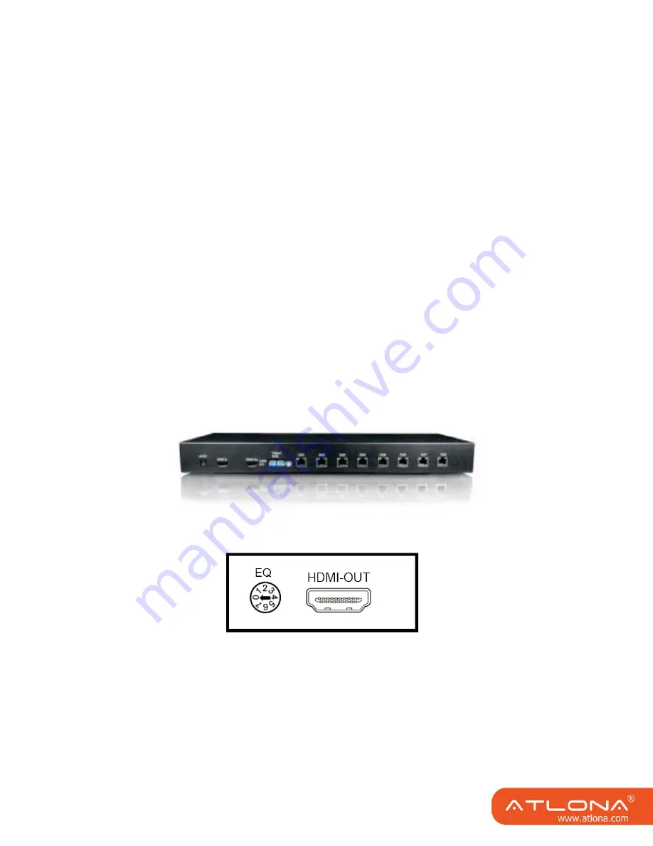
AT-HDRS

HDMI-OUT:

 Connect to HDMI™ display with a HDMI™ M-M cable.

EQ:

 Adjust the 8-level equalization control knob to the received HDMI™ signals.

0 - 7 = strongest - weakest. It is recommended to switch from 7 to 0 to find the optimal 
visual experience.

5                                                   

Содержание AT-HD19SS

Страница 1: ...AtlonA 1x9 HDMI over Single CAT5 Distribution Amplier User Manual AT HD19SS AT HDRS...

Страница 2: ...roduction 1 2 Diagram 1 3 Features 2 4 Technical Specications And Package Content 2 5 Panel Descriptions 3 6 Rotary Switch 4 7 Hardware Installation 6 8 Notice 7 9 HDMI Pin Denition 8 10 Safety Inform...

Страница 3: ...ovides the most exible solution by which high de nition video and high quality audio can be transmitted to different locations over a long distance The devices are cascadable allowing you to extend HD...

Страница 4: ...llation Note The length depends on the characteristics and quality of the cables Higher resolutions and longer transmission distances require low skew cables 25ns 100m for best performance Model Name...

Страница 5: ...Output 1 link to the HDMI over CAT5e receiver 7 RJ45 Output 2 link to the HDMI over CAT5e receiver 8 RJ45 Output 3 link to the HDMI over CAT5e receiver 9 RJ45 Output 4 link to the HDMI over CAT5e rece...

Страница 6: ...EO PATTERNS Rotary Switch Rotary 1 Stereo audio output Rotary 2 Running circles with increasing radius Rotary 3 White Running Circle with Black Background Rotary 4 Black Running Circle with White Back...

Страница 7: ...h at right position DIP Switch Up HDMI mode DIP Switch Down DVI mode Green LED when input detect HDMI in bright For example Output 1 to HDMI TV and Output 2 to DVI monitor Set DIP switch 1 at position...

Страница 8: ...vices including monitors 2 Connect a local HDMI display to the HDMI Out of the AT HD19SS 3 Connect HDMI source such as a Blu ray Disc player to the HDMI In 4 Connect to the receivers AT HDRS via RJ45...

Страница 9: ...ed UTP cables A solid UTP CAT5e cable shows a longer transmission length than stranded STP CAT6 cable For long extension users solid cables are your only choice 3 To reduce the interference among the...

Страница 10: ...TMDS Clock Pin 3 TMDS Data2 Pin 13 CEC Pin 4 TMDS Data1 Pin 14 Reserved N C on device Pin 5 TMDS Data1 Shield Pin 15 SCL Pin 6 TMDS Data1 Pin 16 SDA Pin 7 TMDS Data0 Pin 17 DDC CEC Ground Pin 8 TMDS...

Страница 11: ...plug the device and plug it back in Protect and route power cords so they will not be stepped on or pinched by anything placed on or against them Be especially careful of plug ins or cord exit points...

Страница 12: ...S OF THE THEORYOF LIABILITY ARISING OUT OF OR RELATED TO THE USE OF OR INABILITY TO USE THE PRODUCT EVEN IF ATLONA HAS BEEN ADVISED OF THE POSSIBILITY OF SUCH DAMAGES IN NO EVENT ATLONA S LIABILITY TO...

Отзывы: