Owner’s Manual
TSD-PA10VG
Mono Commercial Power Amplifier
AtlasSound.com
– 4 –
Specifications are subject to change without notice.
1601 Jack McKay Blvd. • Ennis, Texas 75119 U.S.A.
Telephone: 800.876.3333 • Fax: 800.765.3435
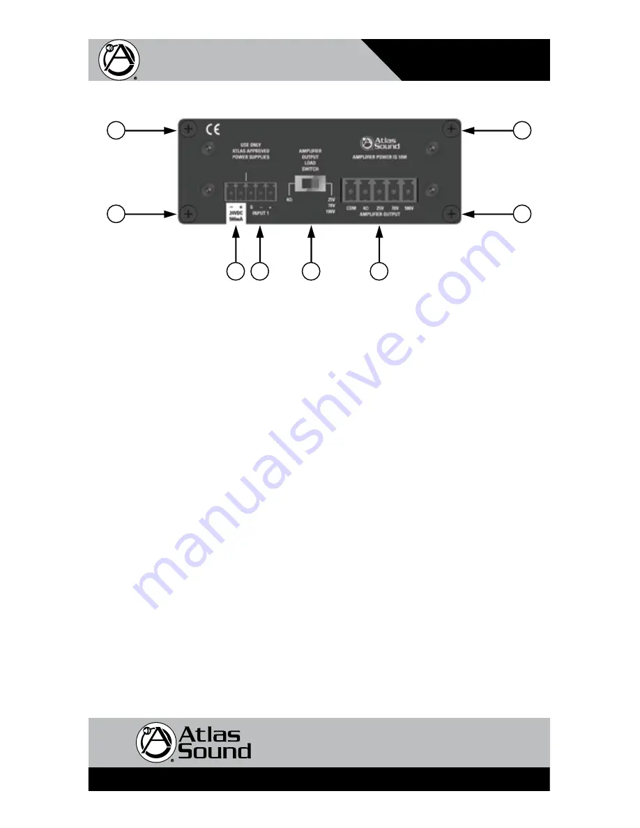
Rear Panel Description
TSD Input/Output connections are removable for easy system wiring. The connectors have a 3.5mm
pitch between pins.
1.
DC Power Input
- Each TSD that requires DC power comes with a 2 position connector for an
external 24VDC power supply (sold separately). Because of the TSDs low power consumption, a
single external power supply may power more than one TSD. Please refer to the specifications
on current requirements in milliamps to match with the appropriate power supply. Please observe
the polarity of the wiring to this connector.
Note:
It is acceptable to exceed the current
requirements of the TSDs but NOT safe to use a power supply that is below the current
requirement of the device.
2.
Balanced Line Input
- Connect balanced line level signals to the phoenix style connectors. Your
connection must be mated properly to the input connector or signal loss and/or noise may occur.
Note:
Unbalanced line level inputs can also be used by connecting the (G) and (-) terminals
together.
3.
Speaker Outputs
- Connect the loudspeaker wiring to these terminals, observing the polarity
shown on the rear of the chassis. For low impedance loads, use the “COM” and 4
Ω
terminals.
For high impedance loads, use “COM” and the proper terminal for your system (25/70/100V). It is
recommended to keep the sum total of tapped loudspeakers to 10W.
4.
Output Load Switch
- For 8
Ω
& 4
Ω
loads place the switch into the 4
Ω
position. For 25/70/100V
speaker systems place the load switch into 25/70/100V position. Failure to do this may cause the
amp to go into protect.
5.
Cable Management Retainer Points
- Use the rear panel screws for connecting the included cable
retainers. Each TSD comes with two cable retainers for simplified cable management.
1
2
3
4
5
5
5
5


