REV. 01 2012
22 / 35
To perform ALU
ƿ
balancing, do as follows:
x
Select the mode ALU1
ƿ
or ALU2
ƿ
that best
fits the available locations.
x
Measure and set the wheel dimensions
automatically or manually. Be sure to set the
dimensions referring to the chapter 6.3.2.2 for
ALU
ƿ
modes.
x
Start a spin.
x
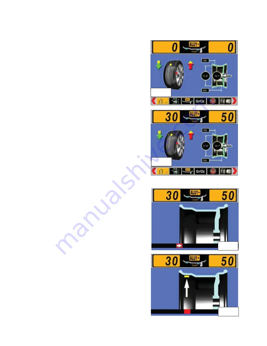
After the spin is completed, the unbalanced
amount will be shown on the screen (ref. fig. 38).
6.4.5.1 CORRECTION OF INNER SIDE
x
Following the arrow direction, rotate the wheel
slowly by hand until the yellow dot on the inner
side moves to the 12 o
’
clock position, and the
arrow changes to be green color and points to the
12 o
’
clock position.
x
Place the correct adhesive weights on the pusher
of A/D gauge.
x
Move the A/D gauge with the adhesive weight on
it. At this time an arrow is shown on the screen
for indication to apply the weights (ref. fig. 39).
x
Continue to move the pusher of the A/D gauge to
the position indicated by the arrow on the screen
(ref. fig. 40).
x
Apply the weight by hand onto the position of
inner side of the rim.
x
Release the A/D gauge, the program will return
to the dimension screen.
Fig. 37
Fig. 38
Fig. 39
Fig. 40
Содержание WB55
Страница 1: ......
Страница 35: ...REV 01 2012 35 35 CHAPTER 12 ELECTRIC DIAGRAM...


