


15
8.
Install the bearing stop ring.
Ring installed.
9.
Lubricate and install the bit bearing.
Bit bearing installed.
10. Install the bearing retaining ring. Start at one end of the cord
and force it into the groove below the bearing all the way around.
11.Place the chuck, drive pins, and retrieval sleeve (if equipped)
over the bit. Install bit retaining rings with o-ring. Lubricate the
exhaust tube with rock drill oil and the chuck threads with thread
grease. Install the assembly in the hammer.
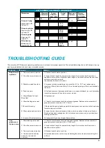
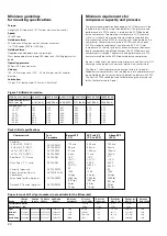
DTH hammer inspection
When a QLX hammer is disassembled, all parts should be
inspected to determine which, if any require replacement, repair,
or reversal. Refer to the specifications to find the appropriate
discard point clearances. The discard point clearances listed
represent an increase in clearance of 50% over the maximum as-
new clearance. In some applications this clearance increase may
represent too much performance loss, and in other applications
additional wear (performance loss) may be acceptable.
Deterioration in drill performance is caused by the increase in
clearance between parts. It is more cost effective to replace the
part that decreases clearance the most at the lowest cost. The
chart in Section 5 tabulates the new diameters from which the
wear on each part can be assessed.
1. Casing outside diameter should be measured roughly 2 to 3 in.
(51 to 76 mm) from the end of the chuck end. Refer to the casing
reverse and discard dimensions to determine if the asing should
be replaced or reversed. Refer to the assembly instructions for
the proper casing reversal procedure.
•
It is suggested that the chuck be replaced when the casing is
reversed.
2. Inspect the chuck
•
Check the overall length of the chuck shoulder against the
specifications. A short chuck shoulder can cause cycling
problems, difficulty handling water, and rough operation.
•
Check the chuck inside diameter. Replace if worn beyond
recommended limits.
•
The chuck should be replaced if spline wear is heavy or
uneven.
•
The chuck should be replaced if its minimum outside diam-
eter is less that the casing discard diameter.
3. Inspect the backhead
•
Check the condition of the connection thread. Replace the
backhead if the threads are torn,galled or damaged, or if the
make-up shoulder is damaged or worn.
•
Check the condition of the internal connection thread. Minor
damage can be repaired by filing or lightly grinding the
damaged area. Replace the backhead if the threads are badly
worn, damaged or cracked.
•
Polish or clean valve stem of debris/corrosion.
4. Inspect the backhead o-ring and replace if damaged.
THREAD
SHOULDER
O-RING
CONDITION CONDITION CONDITION
5. QLX 35: Inspect the check seal. Replace if cracked, torn, or if
the seal is brittle. Check valve O-ring for all other.
6. Inspect the guide for wear, scoring, or galling. Replace if worn
beyond tabulated limits. A wear pattern on one side of the guide
can indicate misalignment in the drill. If this condition is ob-
served, check other parts carefully to identify the source of the
misalignment.


