


7
6
General care instructions
To ensure that your Secoroc GM RH grinding machine functions
satisfactorily for a long time:
Use original spare parts only.
Read the maintenance instructions carefully before putting
the machine to work.
Keep the machine clean.
Check the water cooling regularly.
Electricity supplies must always be disconnected during
installation, servicing and moving of the machine.
If the machine is not going to be used for a long time, make
sure that it is lubricated and cleaned before being left idle.
Installation
WARNING
Always follow the safety instructions with regard to
installation, operation and maintenance.
There is a lifting eye on the upper part of the frame. Always
make use of the lifting eye when hoisting the machine into place.
The weight of the machine is normally 90 kg.
To be able to work, the machine needs electricity and hydraulic
fluid.
When installing the hydraulics we strongly recommend you to
use valves on both preassure (P) and return (T) hoses.
When installing the electric wiring we strongly recommend to
connect the red wire to position 87 on the relay controlled by
start key on the rig or connect an optional switch for the grinder
on the rig.
Electricity
WARNING
Electrical connection of the machine is restricted to quali
fied electricians only, be sure to always observe local regula
-
tions in respect of electrical connection.
Check that the electrical data for the machine is compat-
ible with the mains voltage.
The emergency stop does NOT effect the rig if used. It’s only
connected to the grinding machine.
On delivery, a 24 V power
cable is supplied with the machine.
Hydraulics
CAUTION
The maximum permissible working oil pressure for
the grinding machine with hydraulic components is 210
bar.
Visually inspect the hoses for any type of damage
before use of the grinding machine.
The grinding machine uses existing oil filter on the drill rig.
Recommended oil types
< 50 °C
ISO-32
50-60 °C
ISO-46
60-70 °C
ISO-68
Cooling
The drill bit and grinding wheel are cooled with water mist.
Cooling water is switched on automatically when the grinding
spindle starts to rotate. Water is sprayed over the whole of the
grinding wheel.
Cooling is very important to the service life of the grinding
wheel and to the grinding result. If cooling is poor, thermal
stresses can be ground into the cemented carbide button, with
subsequent button breakage as a result. The service life of the
grinding wheel falls dramatically if cooling is poor.
Use splash sheilds and safety goggles when handling cooling
liquids.
Grinding wheel
CAUTION
The grinding wheel is hot immediately after grinding.
Take care not to burn your fingers when changing the grind
-
ing wheel.
Fit the grinding wheel to the grinding spindle.
The small side of the grinding wheel must face away from the
grinding machine. Make sure that the journal of the spindle is
clean and lightly oiled. This will make it easier to remove the
grinding wheel. Do not tighten the screw too hard.
If the grinding wheel cannot be removed using hand force only,
make use of the extractor
supplied with the machine.
Do NOT use impact or excessive force on the
spindle or grinding wheel!
Grinding
DANGER
Always check that there are no traces of explosives in the
flushing holes of the drill bit. To clean out the flushing holes,
ONLY a wooden stick, a length of copper wire or flushing
water may be used.
Beware of the risks of fire or explosion that might be
initiated by sparks from the grinding work.
CAUTION
Never remove the grinding guard from the machine.
Make sure that the grinding station or place of work is
well ventilated.
Always wear goggles, protective clothing, gloves, dust
mask and hearing protection during grinding.
The grinding wheel is hot immediately after grind-
ing. Take care not to burn your fingers when changing the
grinding wheel.
To prevent injuries caused by crushing, avoid moving
parts when the machine is running.
General rules
Adequate cooling is crucial to the service life of the grinding
wheel, and also to the grinding result. Poor cooling can result in
heat stresses being “ground into“ the cemented-carbide buttons,
with button fracture as a result. The service life of the grinding
wheel falls dramatically if cooling is poor.
Pressing the grinding wheel too hard on to the cemented-carbide
button will reduce the service life of the wheel. Both the grind-
ing wheel and the cemented-carbide button can be damaged by
excessive heat generation. A new grinding wheel must always be
“run in“. Start grinding carefully and increase the feed pressure
gradually. This practice will increase the service life of the grind-
ing wheel substantially.
Grinding hints
The rate of bit wear depends on the rock formation, and is
highest in rocks with a high quartz content. A suitable grinding
interval should be determined according to the rate of bit wear. It
is more economical to regrind too early rather than to suffer poor
penetration rates and risk damaging the drill bit through over-
drilling. A few hints about the care of drill bits:
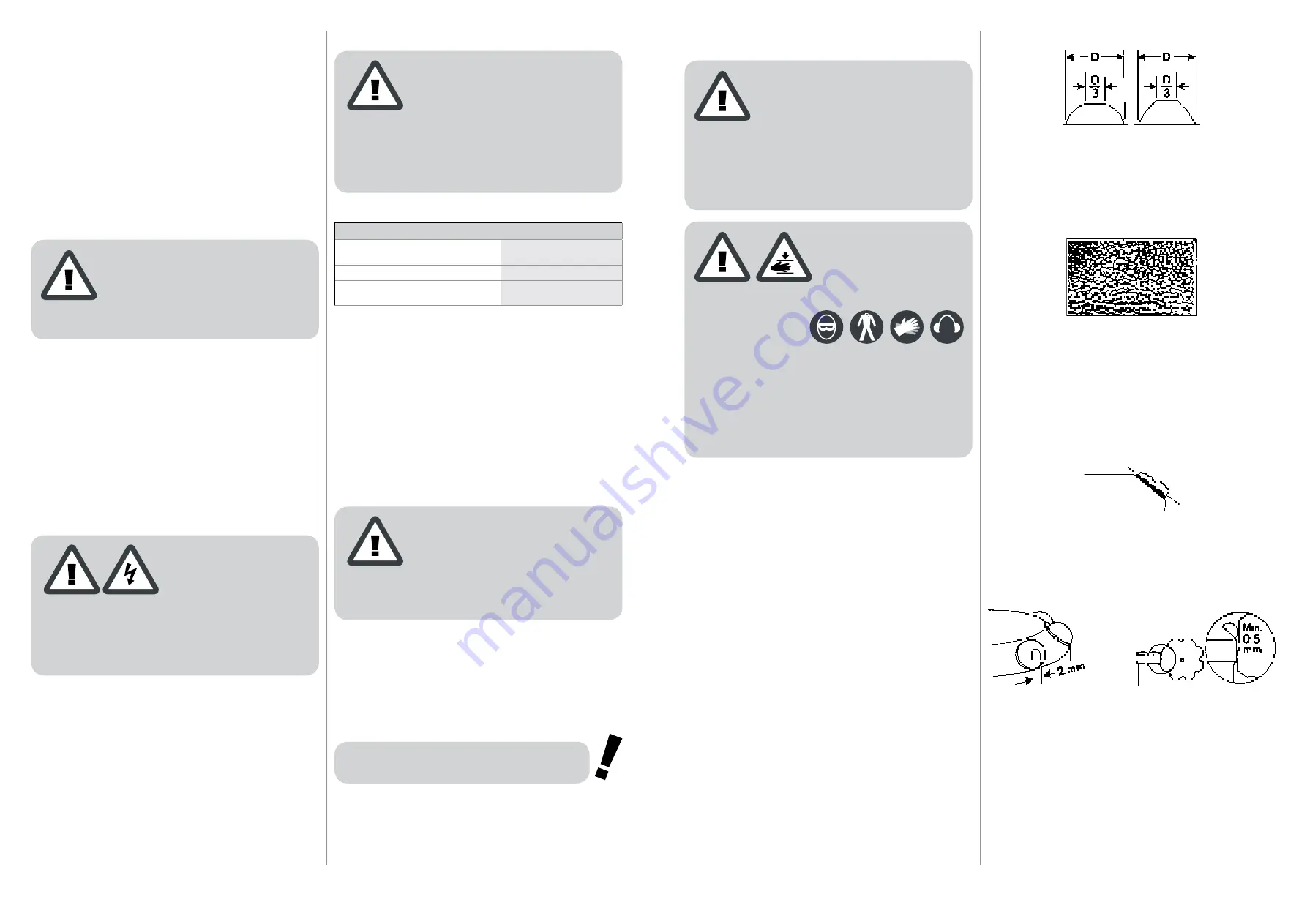
When to regrind
Button bits should be re ground when the pene tration rate drops,
or if any of the cemented-carbide buttons are damaged (fractured
buttons should be ground flat). It is both practical and economi
-
cal to redress the buttons when the wear flat reaches about 1/3 of
the diameter of the button.
Look out for “snake skin“
If microscopic fatigue cracks – so-called “snake skin“ – begin
to appear on the cemented car bide buttons, the cracks must be
ground away. In any event, bits should be reground after 300
metres of drilling at the most.
This should be done even if there are no visible signs of wear
and the penetration rate continues to be good. If snake -skin is not
removed, the cracks will deepen and ultimately result in button
fracture.
Always grind broken buttons flat
A drill bit can remain in service as long as the gauge buttons
maintain the diameter of the bit. Fractured buttons must always
be ground flat to prevent chips of cemented carbide from damag
-
ing the other buttons.
Avoid grinding the perimeter
Gauge button anti-taper has to be removed by grinding, although
excessive reduction of the bit diameter should be avoided. Leave
about 2 mm of the wear flat.
If necessary, remove some of the bit-body steel below the gauge
buttons, so that a clearance (taper) of 0.5 mm is maintained.
Make sure that the flushing holes are open.


