background image

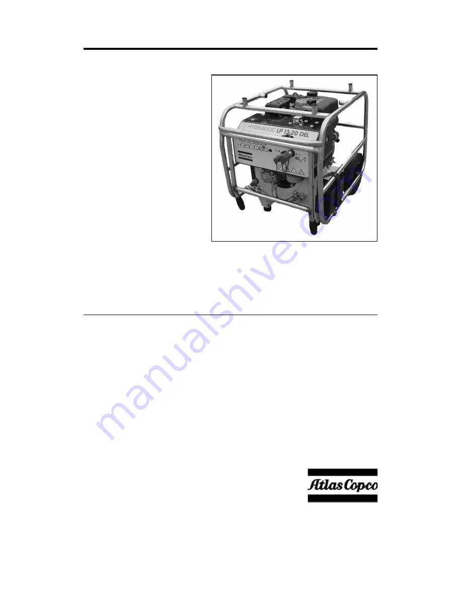
LP 13-20 DEL PAC 


ATLAS COPCO CONSTRUCTION TOOLS AB   

2007-03 

NACKA • SWEDEN 


No. 3392 5146 01 

www.atlascopco.com 


Содержание LP 13-20 DEL PAC

Страница 1: ...LP 13 20 DEL PAC ATLAS COPCO CONSTRUCTION TOOLS AB 2007 03 NACKA SWEDEN No 3392 5146 01 www atlascopco com ...

Страница 2: ...wer Pack 4 GENERAL INFORMATION 4 Parts identification 5 OPERATING INSTRUCTIONS 6 Preparation before starting 6 Starting the engine electric start 7 Starting the engine recoil start 7 Stopping the engine 7 Hydraulic control and connectors 8 Connecting disconnecting hoses 8 How to check the hydraulic system 9 Service schedules 9 Scrapping and waste disposal 10 TROUBLESHOOTING 11 TECHNICAL DATA 12 ...

Страница 3: ...ety standards and form part of the operating instructions Signs and decals that are important for your safety and the care of the Power Pack are included with each power pack Make sure that they are legible New decals can be ordered using the spare parts list The indications DANGER WARNING and CAUTION as used in the safety instructions have the following meanings SAFETY INSTRUCTIONS Before startin...

Страница 4: ...vent make sure to comply with current health and safety regulations and ensure sufficient ventilation Breathing the Power Pack s exhaust gases can harm and possibly kill you Do not start or run the Power Pack in enclosed areas even if the doors and windows are open Start and run the Power Pack outdoors Explosions and fire can be caused by sparks from the exhaust or the electrical system Do not use...

Страница 5: ...las Copco LP 13 20 DEL PAC has therefore no CE marking The Atlas Copco LP 13 20 DEL PAC is therefore not approved for use on the EU market The Atlas Copco LP 13 20 DEL PAC is a hydraulic Power Pack designed for operating Atlas Copco hydraulic breakers and other tools The Power Pack is fitted with a 10 HP Lombardini air cooled 1 cylinder 4 stroke diesel engine with electric start The flow of the LP...

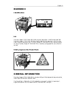
Страница 6: ...ight glass hydraulic oil level 13 Pressure relief valve 4 Filter condition gauge 14 Foldable handles 5 Hydraulic oil filter 15 By pass valve 6 Engine oil dipstick 16 Air filter 7 Starting switch 17 Drain plug 8 Ignition switch OFF and ON 18 Battery 9 Stop lever 19 Throttle lever 10 Oil cooler ...

Страница 7: ...and add as necessary Position the Power Pack in a safe position Ensure that the hydraulic couplings are clean and fully serviceable Ensure that any hydraulic tool you plan to use is compatible with the model of the Power Pack you are using See the section Flow rates Check the engine oil level and add oil as necessary Ensure that you have adequate fuel for the job Top up as necessary taking care no...

Страница 8: ...or about 3 minutes 1 Turn the hydraulic by pass valve A to the OFF position 2 Move the throttle lever C to the low speed position and let the engine run for about 3 minutes without load 3 Move the throttle lever H to the STOP position 4 Turn the ignition key D counter clockwise to the OFF position 5 Slowly pull out the recoil starting handle 12 until resistance is felt and leave the handle in this...

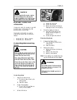
Страница 9: ...ng hoses 1 Prepare the Power Pack a Turn the by pass valve to the OFF position b Stop the engine 2 Remove the hoses a Rotate the collar on the female coupling b Release the return line c Release the feed line Note The couplings are unlocked by mov ing the collar back on the coupling CAUTION When stopping the engine reduce the load slowly Do not stop the engine suddenly since it may cause the tempe...

Страница 10: ... on the flow meter is 2 l p m 0 5 gal min If the performance is not in accordance with the technical speci fications for the Power Pack please see the section TROUBLE SHOOTING A poorly maintained Power Pack is a haz ard Doing regular maintenance and lubri cation jobs as listed in these schedules will help keep the Power Pack in a safe work ing condition Apart from the daily jobs the schedules are ...

Страница 11: ...ch a way that the greatest possible part of them can be re cycled and the influence on the environ ment kept as low as possible IMPORTANT When the filter gauge needle re mains in the red sector while the engine is running idle and the oil is service warm the filter must be replaced The old filter is removed by turning it clockwise use a filter strap wrench if necessary Tilting the Power Pack rearw...

Страница 12: ...Engine does not turn over or is difficult to turn Battery uncharged Start engine with recoil start or recharge battery Damaged hoses Check and replace if needed Leaking connections Check for tightness leaks Low hydraulic oil level Defect hose couplings Replace couplings Low pressure relief valve setting Adjust valve High back pressure Check hose system for blockage Poor tool performance Worn hydra...

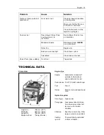
Страница 13: ...em Tool runs hot Tool defect Check and service tool Power Pack stops suddenly Out of fuel Top up tank 1 Dimensions Height A 705 mm 27 7 Width B 600 mm 23 6 Length C 745 mm 29 3 Weight with oil 116 kg 256 lbs Engine type Engine Lombardini air cooled 1 cylinder 4 stroke diesel engine with electric start Performance 10 HP 7 5 kW at 3600 rpm Fuel Diesel Starter Electric start and recoil hand start Hyd...

Страница 14: ... any tool used with the Power Pack is of a compatible category If any doubt consult your Atlas Copco dealer Hose length 1 In normal ambient temperature 0 40 C 32 104 F the maximum hose length should not exceed 25 m 82 ft 2 Normally 7 m of Twin hoses are to be used for the Power Pack Twin hose and other accessories are shown in the spare parts list WARNING The setting of the pressure relief valve o...

Страница 15: ......

Страница 16: ......

Отзывы: