


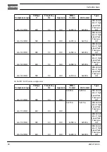

Analogue signals
Minimum
setting
Factory
setting
Maximum
setting
Dp of oil separator (shut-down warning
level)
bar
0
0.8
1.0
Dp of oil separator (shut-down warning
level)
psi
0
11.6
14.5
Delay at signal, Dp of oil separator
sec
0
60
255
Dp of air filter:
Shut-down warning level
mbar
-85
-80
0
Shut-down warning level
psi
-0.7
-0.7
-0.7
Shut-down level
mbar
-85
-85
0
Shut-down level
psi
-1.2
-1.2
-1.2
Delay at signal, Dp of air filter
sec
0
60
255
Dp of DD filter
mbar
100
350
350
Dp of DD filter
psi
1.45
1.45
1.45
Delay at signal
sec
0
60
255
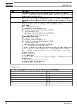
Remark
A number of service operations are grouped (Level A, Level B, ...). Each level stands for a number of service
operations to be carried out at the programmed intervals. Consult your Atlas Copco Service Centre.
Terminology
Term
Explanation
ARAVF
Automatic restart after voltage failure.
See Elektronikon regulator.
Required stop
period/Minimum
stop time
Once the compressor has automatically stopped, it will remain stopped for the minimum
stop time (approx. 20 seconds), whatever the net air pressure. In automatic operation, the
compressor will not be stopped by the regulator until a standstill period of at least the sum
of the minimum stop time and required stop period is expected. However, if the decrease
in net air pressure should require a new start of the compressor, the regulator will start the
compressor after the minimum stop time.
Power recovery
time
Is the period within which the voltage must be restored to have an automatic restart. Is
accessible if the automatic restart is activated. To activate the automatic restart function,
consult Atlas Copco.
Delay at shut-
down signal
Is the time for which the signal must exist before the compressor is shut down. If it is
required to program this setting to another value, consult Atlas Copco.
Instruction book
2920 1728 05
75
Содержание GA 110 VSD
Страница 1: ...GA 110 VSD GA 132 VSD GA 160 VSD Instruction book ...
Страница 2: ......
Страница 17: ...Rear view of air cooled GA Instruction book 2920 1728 05 15 ...
Страница 23: ...Air cooled compressors Instruction book 2920 1728 05 21 ...
Страница 30: ...Instruction book 28 2920 1728 05 ...
Страница 31: ...Instruction book 2920 1728 05 29 ...
Страница 32: ...Instruction book 30 2920 1728 05 ...
Страница 33: ...Instruction book 2920 1728 05 31 ...
Страница 34: ...Instruction book 32 2920 1728 05 ...
Страница 35: ...Instruction book 2920 1728 05 33 ...
Страница 36: ...Instruction book 34 2920 1728 05 ...
Страница 79: ...Dimension drawing of air cooled Full Feature VSD compressors Instruction book 2920 1728 05 77 ...
Страница 83: ...Compressor room example of air cooled GA VSD Full Feature compressor Instruction book 2920 1728 05 81 ...
Страница 100: ...Instruction book 98 2920 1728 05 ...
Страница 101: ...Instruction book 2920 1728 05 99 ...
Страница 103: ...Figure A Instruction book 2920 1728 05 101 ...
Страница 104: ...Figure B Instruction book 102 2920 1728 05 ...
Страница 107: ...Text on figure Instruction book 2920 1728 05 105 ...
Страница 164: ......
Страница 165: ......


