Technical Manual & Parts Lists
26
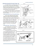
Adjusting Needle Thread Take-Up
The needle thread take-up and thread guide may be
adjusted to increase or decrease the amount of thread
drawn at the top of the needle bar stroke. To increase the
amount, loosen the thread take-up screw, Fig. 34, and raise
the take-up or loosen the guide screw and lower the guide.
To decrease the amount, reverse the adjustment by
lowering the take-up or raising the guide.
For average sewing conditions, the guide should be
set with upper end 5/8” above the guide screw. The thread
take-up should be set with the lower end 1.378” below the
bottom of its holder.
Adjusting Needle Thread Tension Releaser
When correctly adjusted, the tension releaser
should release tension on the needle thread when the
presser foot is raised and allows full adjusted tension
when presser foot is down. To adjust, loosen the set screw,
Fig. 35, and move tension releaser cap out for earlier
release of tension or in for later release. Hold in
position and tighten the set screw. Should the
tension releaser not release tension at the correct
time after making the above adjustments, loosen
the tension releaser plate screw and move plate
sidewise to correct position. Then tighten the
screw.
Adjusting Looper Thread Take-Up
The looper thread take-up and guide may
be adjusted for handling more or less thread,
according to the thickness of material and length
of stitch, and to change the ratio of looper
thread in the finished stitch.
To change the amount of thread handled,
loosen the looper thread guide screw, Fig.
36, and looper thread take-up rod screw.
Move the thread guide and take-up rod to
the left for more thread or to the right for
less thread. Tighten the two screws making
certain that the take-up rod passes through
the center of the guide yoke. To change the
ratio of looper thread in finished stitch,
loosen the thread guide screw, Fig. 36, and
lower the yoke or right end of the thread
guide for more thread. For less thread, raise
the end of the guide. Hold in position and
tighten the guide screw.
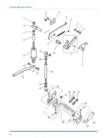
Fig 34
Fig 35
Fig 36
Содержание 1344S88
Страница 2: ......
Страница 32: ...Technical Manual Parts Lists 27 ...
Страница 34: ...Technical Manual Parts Lists 29 ...
Страница 36: ...Technical Manual Parts Lists 31 ...
Страница 38: ...Technical Manual Parts Lists 33 ...
Страница 40: ...Technical Manual Parts Lists 35 ...
Страница 42: ...Technical Manual Parts Lists 37 ...
Страница 44: ...Technical Manual Parts Lists 39 ...
Страница 46: ...Technical Manual Parts Lists 41 ...
Страница 48: ...Technical Manual Parts Lists 43 ...
Страница 50: ...Technical Manual Parts Lists 45 ...
Страница 52: ...Technical Manual Parts Lists 47 ...
Страница 56: ...Technical Manual Parts Lists 51 ...
Страница 62: ...Technical Manual Parts Lists 57 1338SFS88 PD Pneumatic Diagram 125609B ...
Страница 63: ...Technical Manual Parts Lists 58 1338SFS WD Wiring Diagram 125610B ...

