PAGE
69
3.4.2
Work platform height control device
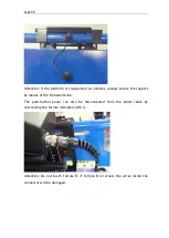
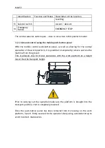
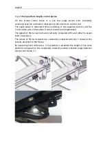
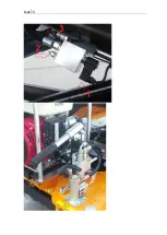
On the scissor frame there is a Can Bus angle sensor that constantly
communicates the inclination measured to the electronic control unit.
The angle sensor is redundant (thus consisting of two separate sensors) and the
Y inclination axis of the scissor frame is monitored (longitudinal)
The signals of the two sensors are constantly compared with each other to assess
their consistency.
The values of the two sensors are constantly compared with the Y values of the
sensors attached to the frame.
By measuring their difference, it is possible to establish the height of the work
platform compared to the completely lowered position (relative angle between
scissors and frame 3°).
Содержание 1470-HE EVO
Страница 7: ...PAGE 7...
Страница 12: ...PAGE 12 Work area on tracks Travel not allowed Maximum inclination allowed 2 5020 5490 7500...
Страница 27: ...PAGE 27...
Страница 28: ...PAGE 28...
Страница 34: ...PAGE 34 Warning Do not tighten the fixing belts too much so as not to damage the eye bolts...
Страница 50: ...PAGE 50 8 Extendible basket pedal...
Страница 57: ...PAGE 57 38 Chassis and stabilisers...
Страница 74: ...PAGE 74...
Страница 76: ...PAGE 76...
Страница 77: ...PAGE 77...
Страница 80: ...PAGE 80...
Страница 87: ...PAGE 87 Attention IT IS FORBIDDEN to block the gate in such a way as to keep access to the platform open...
Страница 137: ...PAGE 137 In this configuration the oil level B must be at a distance of 30mm from the maximum level C...
Страница 138: ...PAGE 138...
Страница 160: ...PAGE 160...
Страница 161: ...PAGE 161...
Страница 162: ...PAGE 162...
Страница 163: ...PAGE 163...
Страница 164: ...PAGE 164...
Страница 165: ...PAGE 165...
Страница 166: ...PAGE 166...
Страница 167: ...PAGE 167...
Страница 168: ...PAGE 168...
Страница 172: ...PAGE 172 6 Using the nut supplied point A 7 Move the front wheel back by pressing on the track with your foot...
Страница 178: ...PAGE 178 MANDATORY ROUTINE INSPECTIONS Date Observations Seal Signature...
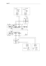
Страница 191: ...PAGE 191 8 4 Hydraulic diagram See attachment 8 5 Wiring diagram See attachment...

