background image

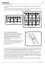
5.2.- Installation and guiding of the electrical cables

All the cables used in the installation must be secured in order to prevent movements
that could cause damage or breakages.

ATERSA solar modules hardly require any maintenance but you must follow a set of
guidelines to ensure good condition.

Our solar modules are made from high-efficiency square cells that are capable of
producing power with low solar radiation. All the models from 75W to 320W have by-
pass diodes in the junction box.

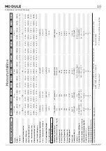
The technical characteristics of the modules are shown in the attached table and
grapichs. View table on page 9 (Polycrystalline) and page 10 (Monocrystalline).

ATERSA guarantees the power output for up to 25 years and provides a 10-year
warranty covering manufacturing flaws.

The modules comply with IEC 61215:2005 and IEC 61730 standards, in addition to
being manufactured under strict UNE-EN ISO 9001:2008, UNE-EN ISO 14001:2004
quality standards.and OHSAS 18001:2007.

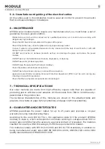
6.- MAINTENANCE

7.-

8.-

x

x
x
x

x

x
x
x
x
x
x

x

Maintenance work should be carried out by qualified personnel, as it could involve working with
dangerously high voltages.

Check that dirt has not accumulated on the glass of the panel.

Should this be the case, clean the glass with a sponge and soapy water

In case if water is not available,Module can be dry cleaned with the help of a soft cloth or with soft
sponge to remove dirt, dust.

DO NOT use brushes or abrasive products as they can damage the glass and reduce the power
module.

DO NOT use any chemical abrasive cleaners, degreasers, or cleaning.

DO NOT use water jet cleaning system.

DO NOT clean the panels at their hottest (midday).

Check the cables and electrical connections.

DO NOT use lubricant oils or sprays to connect the connectors..

Appropriate electrically insulating Personal Protective Equipment (PPE) must be worn during any
cleaning or inspection operations.

Check that the mechanical components are not damaged

.

TECHNICAL SPECIFICATIONS

GUARANTEE AND CERTIFICATES

According to the norm IEC 61730-1, the application class for this product (ATERSA
module) is class A, which corresponds to modules working in voltages above 50V or
powers above 240W where the access to a general contact is forecasted. The modules
clasified for security within this category fulfill the requirements for ClassII.

8

MODULE

Installation and User Manual

EN-MU-41 (4)-E

Содержание A-150M

Страница 1: ...A VALENCIA P Industria Juan Carlos I 46440 Almussafes Valencia Spain Tel 902 545 111 Fax 902 503 355 Avda de la Foia 14 MODULE Installation and User Manual www atersa com Last revision 17 01 2017 Prin...

Страница 2: ...ng installation or maintenance 1 GENERAL SAFETY 1 2 TRANSPORT AND HANDLING 1 3 WARNINGS 2 4 POSITIONING AND INCLINATION 2 5 INSTALLATION 3 7 8 6 MAINTENANCE 8 7 TECHNICAL SPECIFICATIONS 8 8 GUARANTEE...

Страница 3: ...of module back sheet with sharp objects as scratches may directly affect product safety Do not use the junction box to hold or transport the module Broken or damaged modules must be handled carefully...

Страница 4: ...installed on plots of land terraces roofs and patios ATERSA provides a series of accessories for installations on fa ades windows balconies walls and cornices In order to ensure optimum performance t...

Страница 5: ...dent fixed structures The structure must not transmit stress to the modules The longest side of the aluminium frame has a series of 6 7mm diameter drill holes Use M6 stainless steel screws to install...

Страница 6: ...d on standard structures U type guide rail or guide insertion Fixing on standard structures is carried out using the dead end clamp the M8x20 serrated head Allen screw flat washer and M8 nut View imag...

Страница 7: ...icable regulations 5 2 Electrical Installation CABLE SECTION Copper section Put the first two fixing sets in place and ensure they are vertically aligned Fully tighten the Allen screw 6 Attach the oth...

Страница 8: ...ion to the polarity of the wires Make sure that the cable is inside the clip and is fixed correctly if the cable is not installed correctly the juntion box will be deteriorated electric arc After term...

Страница 9: ...e 4mm View image of annex 11 12 The proper torque values should be between 1 5 to 2Nm The photovoltaic system will be earthed according to the local and national regulations 2 It is not recommended to...

Страница 10: ...nvolve working with dangerously high voltages Check that dirt has not accumulated on the glass of the panel Should this be the case clean the glass with a sponge and soapy water In case if water is no...

Страница 11: ...TYCO IP65 15 2 20 25 A 18A 45V 175 C m A 260P A 265P A 290P A 295P A 300P 300 W 15 42 8 21 A 8 89 A 44 97 V 36 52 V A 305P 305 W 0 5 W 15 67 8 27 A 8 78 A 45 97 V 36 88 V A 310P 310 W 0 5 W 15 93 8 35...

Страница 12: ...0 5 W 15 97 8 44 A 8 99 A 37 90 V 30 79 V 0 5 W 15 35 8 24 A 8 79 A 37 62 V 30 35 V 255 W 260 W 250 W A 250M A 255M A 260M 16 27 8 54 A 9 04 A 38 40 V 31 03 V 0 5 W 265 W A 265M A 310M 0 5 W 15 94 45...

Страница 13: ...tion and User Manual Printed on recycled paper UNE EN ISO 14001 UNE EN ISO 9001 ER 0979 1997 GA 2009 0396 OHSAS 18001 SST 0134 2012 Dispose of the device at an environmental disposal point when it rea...

Страница 14: ...ded for the fixation of the laminate and ensure proper installation Always use fastening systems that do not damage the laminate module A 80 mm 11 mm B 13 mm 9 mm B 10 mm 6 4x9 6 4x9 225 25 0 595 25 0...

Страница 15: ...9 mm B 10 mm 6 4x9 6 4x9 General dimensions Monocrystalline modules Module Laminate ANNEX Dimensions in mm The areas marked in the drawing A and B are intended for the fixation of the laminate and ens...

Страница 16: ...ut notice For more extensive information about the terms of the warranty and certificates y please see our website www atersa com 13 13 2 Polycrystalline and Monocrystalline 13 1 Laminate assembly dra...

Отзывы: