background image

QSG_F6CLASS.376.00_EN_01 / 2019-03-25

11 / 32

POWER SUPPLY CONNECTORS

The device can be connected to an external power supply (24 V DC - 2 A) or provided with 
an internal power supply (100 / 240 V AC) (option).

External supply

24 V DC connector (J7)

The device can be connected to a 24 V DC - 2 A power supply through a M12 4 pins type 

connector.

Pin number

Signal

1

Not connected

2

+ 24 V DC

3

Not connected

4

Ground: 0 V

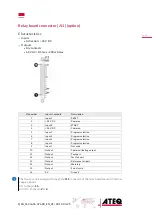
24 V DC on the relay board connector (J11) (option)

The device can also be connected to a 24 V DC - 2 A power supply through J11 connector 

on the relay board.

Pin number

Signal

2

+ 24 V DC

4

+ 24 V DC

16

Ground: 0 V

Apply 24 V DC to the pin 

2

 or 

4

.

Содержание F6Class

Страница 1: ...ATEQ F6Class Quick Start Guide...

Страница 2: ...6Class Front panel 8 Connectors on the back panel with all options 9 Power supply connectors 11 Digital links 12 Digital inputs outputs 12 Pneumatic connectors 15 Pneumatics configuration 17 User inte...

Страница 3: ...teq com cn ateq com cn T 86 21 6763 9508 F 86 21 6763 9528 ATEQ SYSTEMS ANALYSIS TAIWAN CO LTD NO 3 LAN 223 San Jia Dong Street 40642 TAICHUNG TAIWAN ateqtaiwan ateq com tw ateq com tw T 886 4 2437 52...

Страница 4: ...s Read the user manual before using the device All electrical connections to the device must be equipped with safety systems fuses circuit breakers etc adapted to the needs and in accordance with the...

Страница 5: ...ditions impurities must be prevented from being drawn into its internal components For this purpose we strongly recommend that a suitable airtight filter is installed between the part under test and t...

Страница 6: ...st programs LEAK TEST Direct measurement principle The part under test 3 and the reference part 5 are filled to an identical pressure Adifferentialsensor4measuresthepressure variation between the part...

Страница 7: ...19 03 25 7 32 PRINCIPLE OF A CYCLE The measurement cycle is made of 4 main phases fill stabilization test dumping Pressure 0 1 2 4 Time Cycle start Cycle end 3 0 Waiting phase 1 Fill phase 2 Stabiliza...

Страница 8: ...LASS 376 00_EN_01 2019 03 25 8 32 Your ATEQ F6Class FRONT PANEL 1 Display 2 Cycle keys 3 Navigation keys 4 USB connectors 5 Quick connector 6 Mechanical Regulator For more information refer to User in...

Страница 9: ...QSG_F6CLASS 376 00_EN_01 2019 03 25 9 32 CONNECTORS ON THE BACK PANEL WITH ALL OPTIONS...

Страница 10: ...or test pressure input according configuration 7 B Pneumatic output for B automatic connector option 8 A Pneumatic output for A automatic connector option 9 Vacuum input or external regulated pressur...

Страница 11: ...C connector J7 The device can be connected to a 24 V DC 2 A power supply through a M12 4 pins type connector Pin number Signal 1 Not connected 2 24 V DC 3 Not connected 4 Ground 0 V 24 V DC on the rel...

Страница 12: ...his connection for temporary communication Connection to a PC cannot be used permanently because the communication can be disconnected by the PC Printer RS232 connector Modbus option RS232 SubD 9 pins...

Страница 13: ...V DC Common 5 Input 3 Program selection 6 Input 4 Program selection 7 Input 5 Program selection 8 Input 6 Program selection 9 Input 7 Not used 10 Output Common floating output 11 Output Pass part 12 O...

Страница 14: ...tions of connector pins to activate for program selection Program number Pin 5 input 3 Pin 6 input 4 Pin 7 input 5 Pin 8 input 6 Pin 9 input 7 1 0 0 0 0 0 2 1 0 0 0 0 3 0 1 0 0 0 4 1 1 0 0 0 5 0 0 1 0...

Страница 15: ...od practices and safety instructions section A specific filter may be necessary The air is supplied via the filter located on the back panel of the device Metal air filter The metal filter is used for...

Страница 16: ...s parts to be connected test and reference 1 Test connector 2 Reference connector 3 Not used 4 Exhaust output 5 Pressurization output Metallic fitting available for test 1 and reference 2 connectors 2...

Страница 17: ...tion PNEUMATICS CONFIGURATION Direct mode Low range Pressure from 0 to 500 kPa 72 5 PSI Connections Connection Option description 6 to 1 Connection of the reference output to the reference part 5 to 4...

Страница 18: ...nnection Option description 6 to 1 Connection of the reference output to the reference part 5 to 4 Connection of the test output to the part under test Regulator air supply to 2 Connection of the regu...

Страница 19: ...Navigation keys KEYS Cycle keys The cycle keys are used to start and to stop a measurement cycle Key Name Function Start On the Program screen starts a measurement cycle and opens the Measurement cyc...

Страница 20: ...without modifying parameters Smart key Smart key is a programmable key that provides direct access to a function selected by the user Key Name Function Smart key Starts a measurement cycle default pro...

Страница 21: ...standard conditions function is validated Refer to the Reference Manual The MAIN MENU screen The MAIN MENU screen gives access to different sections for managing the device and the test parameters Acc...

Страница 22: ...screen Pr 001 LEAK TEST PREPARING A PROGRAM Use this procedure to configure a new test program On the MAIN MENU screen ACCESSING THE PARAMETERS 1 Select PARAMETERS using the up down keys and press MA...

Страница 23: ...ng device or enter a password before modifying a parameter On the PARAMETERS screen of the program see Preparing a program 1 Press up down to select the parameter to modify and press TYPE LEAK TEST CO...

Страница 24: ...With the desired program displayed on the Program screen STARTING A MEASUREMENT CYCLE 1 Press Start Thecyclephasesoftheprogramaresuccessivelydisplayed FILL stabilization TEST DUMP 2 At the end of the...

Страница 25: ...arameters are displayed when specific functions are activated Label Special cycle Description of the cycle Custom Unit Learn Custom unit learn Define unit on a master leak Custom Unit Check Custom uni...

Страница 26: ...PSI Pa kPa MPa Max FILL Maximum fill pressure Maximum level of the fill pressure Min FILL Minimum fill pressure Minimum level of the fill pressure LeakUnit Reject unit Measurement units Test FAIL Test...

Страница 27: ...parameter MINI VALVE Mini valve Access to highest time resolution fast test and auto zero time NAME Name Program customization NO NEGATIVE No Negative Replace negative value per 0 N TESTS N TESTS Repe...

Страница 28: ...ograms DUMP LEVEL Configuration of the minimum dump level pressure BLOW MODE Blowing mode when test cycle is not running option DUMP OFF Remove dump time parameter on the selected program that becomes...

Страница 29: ...am version built in components etc SERVICE CYCLES Special service cycles Allows to display more special cycles to carry out device internal tests see Service special cycles RESET PARA Parameters reset...

Страница 30: ...save and restore parameters on an external USB device Save parameters Restore parameters MAIN USB Label Description Save parameters Save parameters on an external USB memory device for restoring later...

Страница 31: ...rical power supply 24 V DC 2 A Overvoltage category II Pneumatic air supply 0 to 0 5 MPa 0 to 72 5 PSI range Air supply 0 6 MPa 87 PSI 15 Pneumatic air supply 0 6 to 1 MPa 87 to 145 PSI range Regulato...

Страница 32: ...QSG_F6CLASS 376 00_EN_01 2019 03 25 32 32...

Отзывы: