background image

10

SCA2

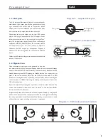
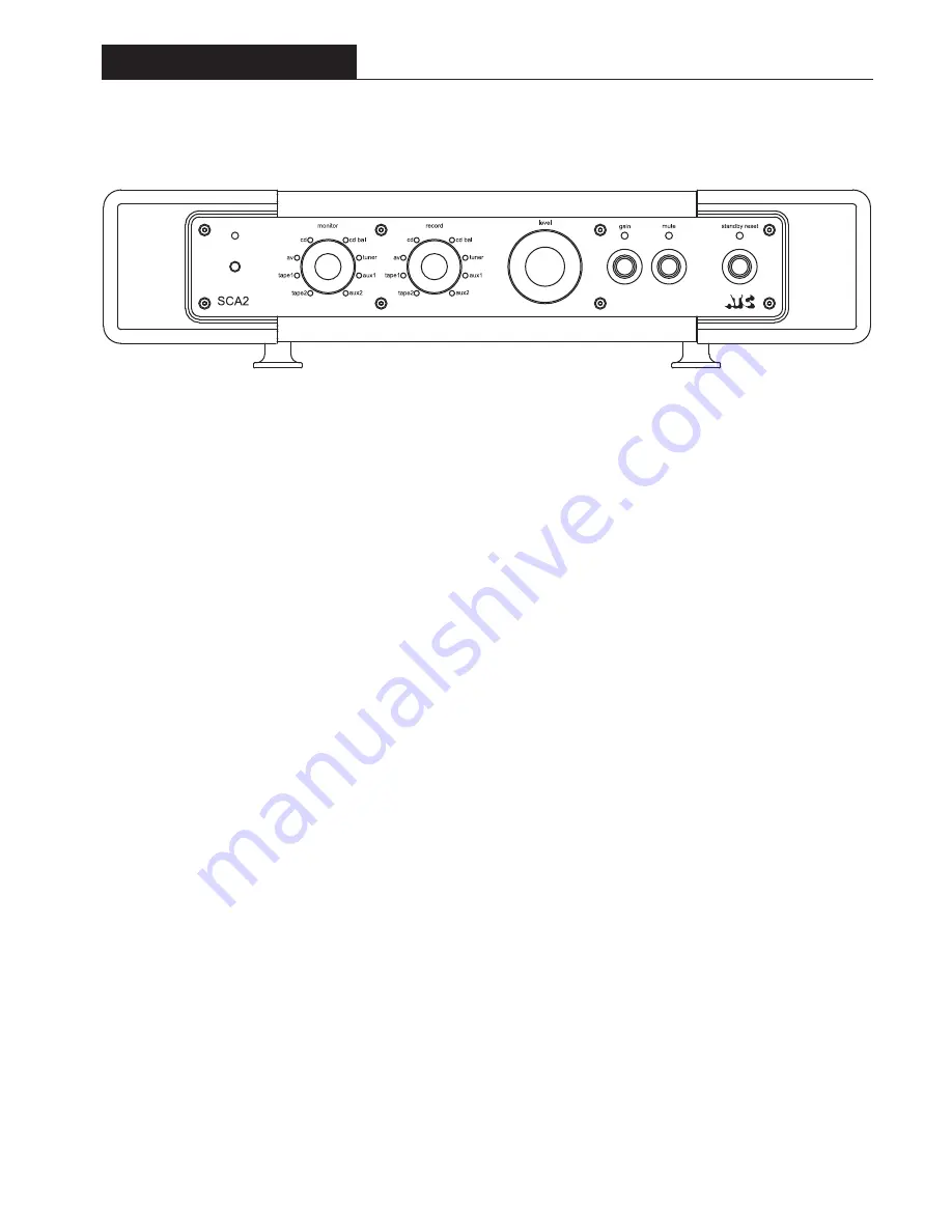
Diagram 6 - SCA2 front panel and controls

2 . 4   O p e r a t i o n

Once connected to mains power and powered-up 
from the rear panel mains switch, the front panel 

Standby Reset

 button (or remote handset Standby 

button) will switch the SCA2 between standby and 
active modes. In standby mode the Standby Reset 
indicator  will  illuminate.  Operating  the  Standby 
Reset  function  will  switch  the  SCA2  into  active 
mute  mode.  The  Standby  Reset  indicator  will 
extinguish  and  the  Mute  indicator  will  illuminate. 
The 

Mute

 function automatically engages when the 

SCA2  is  switched  from  standby  to  active  mode. 
This precautionary feature provides an opportunity 
for  the  volume  and  input  settings  to  be  checked 
before audio is passed to the power amplifiers.

If  all  is  well,  the  SCA2  may  be  brought  into  full 
operation by pressing the Mute function. The Mute 
indicator will extinguish. The Mute function can be 
used at any time to silence the system.

Inputs are selected by rotating the 

Monitor

 select 

control. The green indicator next to each monitor 
option  will  illuminate  to  indicate  selection.  The 
control  has  continuous  movement.  When  it  is 
moved to the last input, further rotation will select 
the first input. 

Volume  level  is  adjusted  by  rotating  the 

Level


control. A  red  indicator  on  the  control  indicates 
the level selected.

Volume level can be reduced immediately by 12dB  
by operating the 

Gain

 function. The Gain indicator 

illuminates to indicate its use.

Optimum  sound  quality  will  be  achieved  when  the  SCA2  has  reached  normal 
operating  temperature  and  for  this  reason  it  is  recommended  that  it  be  left  in 
standby mode when not in use. It is a wise precaution however to switch-off the 
SCA2  from the rear panel power switch if it is to be left unused for an extended 
period.

The 

Record

 select control selects the input source routed to the tape outputs. The 

green indicator next to each record option will illuminate to indicate selection. The 
control  has  continuous  movement. When  it  is  moved  to  the  last  input,  further 
rotation will select the first input. The  source selected is made available at the tape 
output sockets and is fully buffered to prevent signal interaction. The Level, Gain and 
Mute functions have no effect on the record output signals.

Tape copying can be performed by selecting Tape 1 on the Record control to copy 
from Tape 1 to Tape 2. In this case no signal will be routed to the Tape 1 output 
sockets. Copying from Tape 2 to Tape 1 can be achieved in a similar manner.

Selecting Tape 1 on the Monitor control while also recording to Tape 1 (i.e. tape 1 
is also selected on the record control) enables the off-tape signal from a three head 
tape machine to be monitored. The Tape 2 circuit works in an identical manner.

Due to the nature of the electronics in ATC amplifiers it is quite normal for a sound 
to be heard from the speaker when the power is applied or disconnected. The noise 
heard  will  not  damage  the  speaker  and  is  quite  normal. Although ATC  uses  the 
highest-grade components, a different noise may be heard from each speaker due to 
slight tolerance variations in the amplifier components.

P r e a m p l i f i e r

Содержание CA2

Страница 1: ...A C O U S T I C E N G I N E E R S A T C E l e c t r o n i c s U s e r O p e r a t i n g M a n u a l ...

Страница 2: ...ord of the appliance should be unplugged from the outlet when left unused for a long period of time 12 Object and liquid entry care should be taken so that objects and liquids do not fall into the appliance 13 Damage requiring service the appliance should be serviced by qualified service personnel when i the power supply cord or the plug has been damaged ii objects have fallen or liquid has been s...

Страница 3: ...roughtATC into electronics design and engineering Active speakers demand multiple power amplifiers so ATC from the mid 1980s became not just a loudspeaker manufacturing company but an electronics manufacturer too The further step from electronics for active speakers to a range of stand alone amplifier products was natural and now means that ATC engineering is available from the recording desk or C...

Страница 4: ...r and Record selection can be made by pressing the desired monitor or record button The SCA2 front panel source indicators will illuminate but the rotary controls will not rotate Volume is controlled through the handset Level and buttons The SCA2 front panel Level control will rotate in response to handset level commands The handset Attn button is equivalent to the front panel Gain function The ha...

Страница 5: ...panel push button The tape output is a duplicate of the source selected by the input selector Standby is also accessible from a front panel push button Mains power is applied from a rear panel mounted switch All CA2 functions are duplicated on the ATC remote handset 1 2 Inputs The CA2 accepts unbalanced RCA phono style input plugs The signal is present on the centre conductor of an unbalanced inpu...

Страница 6: ...ing them gently away from the board with a small pair of pliers and replaced in the appropriate positions as shown in the diagram moves links Unused links can be parked on the board by setting them at right angles on unused pins Jumpers J2 and J5 set the input load for each channel of the cartridge With the jumper in place the load is 100 ohms With the jumpers removed the load is 47k ohms Jumpers ...

Страница 7: ...by button or remote handset Standby button will switch the CA2 between standby and active mode In Standby mode the Standby Indicator glows RED Operating the Standby function from either the front panel or the remote handset will switch the CA2 into active mode The RED indicator will extinguish and be replaced by the Input select indicator showing the current selection in GREEN Operating the Standb...

Страница 8: ...vel is controlled by the rotary Volume control on the front of the unit the position of which is indicated by a black pointer Rotating the control clockwise will increase the output level It is good practice to lower the volume setting before switching on the preamplifier or any associated equipment or while changing the input selection Unity gain though the CA2 from any of the line level inputs i...

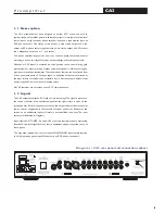
Страница 9: ...hrough a precision motorised potentiometer Mute gain and standby functions are also accessible from font panel push buttons Mains power is applied from a rear panel mounted switch All SCA2 functions are duplicated on the ATC SCA R remote control handset P r e a m p l i f i e r 2 2 Inputs The SCA2 can accept two balanced XLR inputs and six unbalanced RCA phono style inputs 2 as part of tape record ...
Страница 10: ... fitted input tuner tuner RCA phono x 2 input tv av a v RCA phono x 2 input cd cd RCA phono x 2 input tape 2 tape 2 RCA phono x 2 Part of record listen set input tape 1 tape 1 RCA phono x 2 Part of record listen set Z1 Z2 Z3 X X Y Y Resistor bank See Diagram 3 Capacitor bank See Diagram 3 Link across for 400 ohms Link across for 500 ohms Link across for 300 ohms Link across for 600 ohms Link acros...

Страница 11: ...liers and manufacturers will be able to provide details of the loading and gain settings appropriate to their products On some occasions there will be no specific recommendation for the capacitive load on moving coil cartridges In these cases it is best to assume no capacitance need be selected no links used The rear panel ground terminal should be used to connect the pick up arm earth lead 2 3 Ou...

Страница 12: ...l be achieved when the SCA2 has reached normal operating temperature and for this reason it is recommended that it be left in standby mode when not in use It is a wise precaution however to switch off the SCA2 from the rear panel power switch if it is to be left unused for an extended period The Record select control selects the input source routed to the tape outputs The green indicator next to e...

Страница 13: ...B S N N Ratio 95dB Wide band 104dB DIN 108dB IEC A Residual noise 116dB IEC A Absolute phase Phono Unbalanced Zero Degress XLR Balanced Zero Degrees Pin 2 Hot XLR CMRR 100Hz 10kHz 90dB Power Requirements 100V 120 220 230V 50 60Hz Power Consumption 35VA maximum Dimensions including terminals H100 x W440 x D360mm H3 9 x W17 3 x D14 2 inches Weight 9 5kg 20 9lb Net 11 0kg 24 2lb Packed SCA2 P r e a m...

Страница 14: ...te control operation in which case when the Amplifier is switched on the unit will not be in Standby The Red L E D will be off and the remote control has no effect 3 2 Inputs Single ended Inputs via RCA phono sockets and Differential balanced Inputs via XLR sockets are provided Each channel has two phono Input sockets the Link Input phono sockets may be used to connect the Amplifier Inputs to a fu...

Страница 15: ...er back into standby right output output left input link out balanced input balanced input input link out fuse NO USER SERVICEABLE PARTS INSIDE CAUTION RISK OF ELECTRIC SHOCK DO NOT OPEN WARNING THIS EQUIPMENT MUST BE EARTHED P2 High Performance Dual Mono Stereo Power Amplifier Designed and manufactured by Acoustic Transducer Company Gloucestershire GL6 8HR England power I O RETURN TO MANUFACTURER ...

Страница 16: ...LR S N N Ratio 100dB Wideband 110dB DIN 115dB IEC A Crosstalk 100dB 10Hz 20kHz Damping Factor 400 8 Ohms Absolute Phase Zero Degrees Phono Zero Degrees XLR Pin 2 Hot XLR Common Mode Ratio 60dB 100Hz 10kHz Power Requirements 115 230V factory set 50 60Hz Power Consumption 1000W Maximum Dimensions H x W x D Weight E O E The policy of Loudspeaker Technology Ltd is that of continuous design and develop...

Страница 17: ...d input and the signal return is made via the screened outer If there is any hum present on the inputs this must be traced to its source and not suppressed by the removal of screens or earths Removal of the screen on an unbalanced input is likely to result in uncontrollably loud hum The input sockets are illustrated in diagram 1 All inputs are line level sensitivity via RCA phono connectors on the...

Страница 18: ...controls will not affect this output providing mains power is maintained A pair of phono sockets on the rear panel can be used to drive another amplifier A further pair of phono sockets can be used to drive a Sub channel Amplifier Diagram 2 SIA2 150 front panel and controls I n t e g r a t e d A m p l i f i e r A Headphone output is provided via a Jack socket to drive a variety of popular headphon...

Страница 19: ...put Impedance 20k Ohms S N N Ratio 100dB Wideband Crosstalk 90dB 10Hz 20kHz Absolute Phase Zero Degrees Phono Power Requirements 100 115 230V factory set 50 60Hz Power Consumption 10VA Standby 500VA Maximum Dimensions H x W x D 135 x 435 x 350mm Including terminals 5 31 x 17 1 x 13 8 inches Weight 22 2kg 48 8lbs Packed E O E The policy of Loudspeaker Technology Ltd is that of continuous design and...

Страница 20: ...e trading name and ATC is the registered trade mark of Loudspeaker Technology Ltd Loudspeaker Technology Ltd Gypsy Lane Aston Down Stroud Gloucestershire GL6 8HR United Kingdom Telephone 01285 760561 Fax 01285 760683 Email info atc gb net Web www atcloudspeakers co uk ...

Отзывы: