


5-4
Connecting Peripherals
________________________________________________________________________________________________
________________________________________________________________________________________________
________________________________________________________________________________________________
CONNECTING THE MAINTENANCE MODEM
Use this procedure to connect the Hayes
Smartmodem
OPTIMA
2400 for remote access
maintenance. You will set up the maintenance modem software options in AUDIX Voice Power System
R3.0 Software Installation, Chapter 7, Setting Up Peripherals.
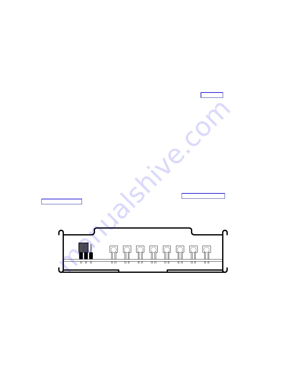
1. Remove the front panel of the maintenance modem.
2. Remove the jumper from pins 2 and 3 and place it on pins 1 and 2 as shown in Figure 5-3.
3. Replace the front panel.
4. Place the maintenance modem near a power source, a telephone line modular jack, and the WGS.
5. Connect the male end of the RS232 M/F cable to COM1 (or serial port 1) on the WGS. Connect the
female end to the maintenance modem.
6. Plug one end of an RJ11 telephone cord (D4 cord) into the modular telephone jack. Plug the other
end into the
LINE
jack on the back panel of the maintenance modem.
7. If you plan to share the telephone line between the maintenance modem and a telephone, plug a
second RJ11 telephone cable into the telephone set. Plug the other end into the
PHONE
jack on the
back panel of the maintenance modem.
8. Plug one end of the power cord into the
PWR
jack on the back panel of the maintenance modem. Plug
the other end into an AC outlet.
If you are connecting a printer, continue with the next section, Connecting the Printer.
If you are not connecting a printer, skip the next section and continue with Chapter 6, Performing
Operational Testing.
FRONT PANEL REMOVED
Figure 5-3. Place the Jumper on Pins 1 and 2 of the Maintenance Modem