


3-1
3. System Diagrams
Chapter Overview
This chapter contains diagrams for the following
Rubber Track Loader systems.
•
Filtering and cooling system
•
Auxiliary circuit system
•
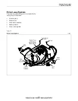
Drive loop system
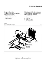
Filtering and Cooling System
The filtering and cooling system (Figure 3-1) con-
tains the following major components.
•
Hydraulic reservoir
•
Radiator/oil cooler
•
Loader valve
•
Auxiliary gear pump
•
Pilot control manifold
Figure 3-1
Filtering and Cooling System
3-001
50-Micron
Suction Screen
10-Micron
Return Filter
Hot Oil Temp
Sending Unit
100 PSI
Cooler Relief
Radiator/Oil
Cooler
Loader
Valve
Hydraulic
Reservoir
Auxiliary
Gear Pump
Pilot Control
Manifold
https://www.tractormanualpdf.info/
Содержание RC30
Страница 5: ...https www tractormanualpdf info ...
Страница 11: ...https www tractormanualpdf info ...
Страница 13: ...https www tractormanualpdf info ...
Страница 17: ...https www tractormanualpdf info ...
Страница 33: ...https www tractormanualpdf info ...
Страница 51: ...https www tractormanualpdf info ...
Страница 61: ...https www tractormanualpdf info ...
Страница 69: ...https www tractormanualpdf info ...
Страница 77: ...https www tractormanualpdf info ...
Страница 103: ...https www tractormanualpdf info ...
Страница 109: ...https www tractormanualpdf info ...
Страница 115: ...https www tractormanualpdf info ...


