background image

VivoMini Séries VC65

49

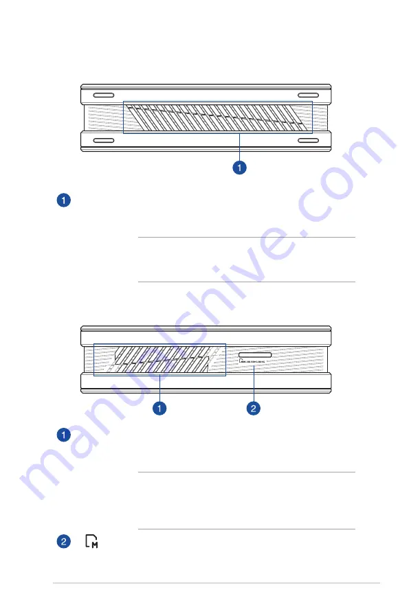
Côté gauche

Côté droit

Orifices de ventilation

Ces orifices permettent à l'air frais de pénétrer à l’intérieur du 

châssis et de refroidir le vivoMini.

IMPORTANT ! 

Assurez-vous qu'aucun objet ne bloque 

les orifices de ventilation pour éviter tout risque de 

surchauffe.

Orifices de ventilation

Ces orifices permettent d'expulser l'excès de chaleur du châssis 

de votre vivoMini.

IMPORTANT ! 

Pour garantir un dissipation optimale de 

la chaleur, maintenez une distance de séparation d'au 

moins 10 cm entre l'arrière du châssis du vivoMini et 

d'objets environnants.

Fente pour carte mémoire

Le lecteur de cartes mémoire intégré à l'ordinateur prend en 

charge les cartes mémoire aux formats MMC, SD, SDHC et SDXC.

Содержание VivoMini VC65R

Страница 1: ...VivoMini VC65 Series User Manual ...

Страница 2: ... A COMMITMENT BY ASUS ASUS ASSUMES NO RESPONSIBILITY OR LIABILITY FOR ANY ERRORS OR INACCURACIES THAT MAY APPEAR IN THIS MANUAL INCLUDING THE PRODUCTS AND SOFTWARE DESCRIBED IN IT Copyright 2015 ASUSTeK COMPUTER INC All Rights Reserved LIMITATION OF LIABILITY Circumstances may arise where because of a default on ASUS part or other liability you are entitled to recover damages from ASUS In each suc...

Страница 3: ...o your VivoMini 15 Connect a display panel to your VivoMini 16 Connect the USB cable from keyboard or mouse 18 Turn on your VivoMini 19 Turning your VivoMini off 20 Putting your VivoMini to sleep 20 Entering the BIOS Setup 20 Quickly enter the BIOS 21 Upgrading yourVivoMini Installing 2 5 hard disk drive solid state drive 23 Upgrading memory modules 28 Appendix Safety information 33 Setting up you...

Страница 4: ... affichage au VivoMini 55 Connecter un clavier ou une souris USB 57 Allumer le VivoMini 58 Éteindre le VivoMini 59 Basculer le VivoMini en mode veille 59 Accéder à l interface de configuration du BIOS 59 Accès rapide à l interface de configuration du BIOS 60 Mise à niveau de votreVivoMini Installer un disque dur de 2 5 pouces ou un lecteur SSD 62 Mise à niveau des modules mémoire 67 Appendice Cons...

Страница 5: ...id state drive of your VivoMini Appendix This section includes notices and safety statements your VivoMini Conventions used in this manual To highlight key information in this manual some text are presented as follows IMPORTANT This message contains vital information that must be followed to complete a task NOTE This message contains additional information and tips that can help complete tasks WAR...

Страница 6: ...oduct specifications and package contents may vary depending on the model type country or region The availability and quantity of these items vary with your VivoMini package If the device or any of its components fail or malfunction during normal or proper use and it is still within the warranty period bring the device and the warranty card to you nearest ASUS Service Center VivoMini ...

Страница 7: ...VivoMini VC65 Series 7 ...

Страница 8: ...1 Getting to know your VivoMini ...

Страница 9: ...nplug the power cable Drive activity indicator This indicator lights up when your VivoMini is accessing the internal storage drive USB 3 0 port The USB 3 0 Universal Serial Bus 3 0 port provides a transfer rate up to 5 Gbit s and is backward compatible to USB 2 0 Power button The power button allows you to turn the VivoMini on or off You can also press the power button once to put your VivoMini to...

Страница 10: ...ir flow ensure that the air vents are free from obstructions Air vents The air vents allow air to exit your VivoMini chassis IMPORTANT For optimum heat dissipation and air ventilation ensure that the air vents are free from obstructions Memory card slot This built in memory card reader slot supports MMC SD SDHC and SDXC card formats ...

Страница 11: ...are USB 2 0 ports Top cover lock latch Kensington security slot The top cover lock latch fastens the top cover on your VivoMini The Kensington security slot allows you to secure your VivoMini using Kensington compatible VivoMini security products DisplayPort The DisplayPort sends high performance digital output from your VivoMini to a display device such as an LCD TV or HD monitor Rear panel ...

Страница 12: ...rt allows you to connect amplified speakers or headphones Microphone jack The microphone jack is designed to connect to a microphone used for video conferencing voice narrations or simple audio recordings VGA port This port allows you to connect your VivoMini to an external display USB 3 0 port The USB 3 0 Universal Serial Bus 3 0 port provides a transfer rate up to 5 Gbit s and is backward compat...

Страница 13: ...VivoMini VC65 Series 13 Air vents The air vents allow air to enter your VivoMini chassis IMPORTANT For optimum air flow ensure that the air vents are free from obstructions ...

Страница 14: ...2 Using your VivoMini ...

Страница 15: ...0V power source IMPORTANT We strongly recommend that you use only the AC power cord that came with your VivoMini We strongly recommend that you use a grounded wall socket while using your VivoMini The socket outlet must be easily accessible and near your VivoMini To disconnect your VivoMini from its main power supply unplug your VivoMini from the power socket Power adapter information Rating 100 2...

Страница 16: ...playPort connector VGA connector DVI connector use with an HDMI DisplayPort VGA to DVI adapter NOTE The HDMI to DVI adapter DisplayPort to DVI adapter or VGA to DVI adapter are each sold separately To connect a display panel to your VivoMini Connect a display cable either to the HDMI DisplayPort or VGA port Connecting display via HDMI port Connecting display via DisplayPort port ...

Страница 17: ...VivoMini VC65 Series 17 Connecting display via VGA port ...

Страница 18: ...ny USB keyboard and mouse to your VivoMini You can also connect a USB dongle for a wireless keyboard and mouse set To connect a keyboard and mouse to your VivoMini Connect the USB cable from your keyboard and mouse to any of the USB ports of your VivoMini Connecting keyboard or mouse via USB port ...

Страница 19: ...VivoMini VC65 Series 19 Turn on your VivoMini Press the power button to turn on your VivoMini ...

Страница 20: ...em startup in the VivoMini In normal circumstances the default BIOS settings apply to most conditions to ensure optimal performance Do not change the default BIOS settings except in the following circumstances An error message appears on the screen during the system bootup and requests you to run the BIOS Setup You have installed a new system component that requires further BIOS settings or update...

Страница 21: ...ton again to turn your VivoMini back on then press F2 or Del during POST When your PC is off disconnect the power cord from your VivoMini s power connector Reconnect the power cable and press the power button to turn on your VivoMini Press F2 or Del during POST NOTE POST Power On Self Test is a series of software controlled diagnostic tests that run when you turn on your PC ...

Страница 22: ...3 Upgrading your VivoMini ...

Страница 23: ...ll cables and peripherals 2 Place the VivoMini on a flat stable surface with its top side facing up 3 Remove the screw from the top cover lock latch and push the latch down A and B then slide the top cover towards the rear of your VivoMini C until it is detached from the chassis 4 Lift and remove the top cover D and set it aside 5 Remove four 4 screws from the HDD SSD bracket ...

Страница 24: ...24 VivoMini VC65 Series 6 optional To upgrade your HDD SDD first remove the four 4 screws on the bracket then remove the bracket HDD1L HDD1R ...

Страница 25: ...HDD1R and PWR1 connectors in your VivoMini HDD1L PWR1 HDD1R NOTE Ensure to remove the holder from the bracket when installing an HDD SDD to the HDD1R bracket The availablility of the holder may vary depending on the model type country or region Connect to HDD1L connector Connect to PWR1 connector Connect to HDD1R connector HDD1L HDD1L HDD1R HDD1R ...

Страница 26: ...n align the bracket to the HDD SSD compartment of your VivoMini and secure the bracket with the screws previously removed NOTE Ensure to organize the cables to prevent any damage to your VivoMini and to ensure the top cover can be replaced successfully HDD1L HDD1R ...

Страница 27: ...VivoMini VC65 Series 27 10 Replace the top cover A your VivoMini and slide it towards the front of the VivoMini to re attach B then push the latch up and secure it using a screw C and D ...

Страница 28: ...um of 16GB memory IMPORTANT Refer to http www asus com for the list of compatible DIMMs You can only install 1 35 V DDR3L SO DIMM to the VivoMini s DIMM slots To install or upgrade the memory modules 1 Follow steps 1 4 under the Installing 2 5 hard disk drive solid state drive section to remove the top cover of your VivoMini 2 Remove four screws from the HDD1L bracket and remove the bracket HDD1L ...

Страница 29: ...VivoMini VC65 Series 29 3 Pry the SO DIMM slot cover open then set it aside NOTE If you want to remove the SO DIMM slot cover use a flathead screwdriver ...

Страница 30: ...ways install into the lower slot first 4 Align and insert the memory module into the slot A and press it down B until it is securely seated in place Repeat the same steps to install the other memory module 5 Replace the SO DIMM slot cover ...

Страница 31: ...moved previously 7 Follow step 10 under the Installing 2 5 hard disk drive solid state drive section to replace the top cover of your VivoMini NOTE Ensure to organize the cables to prevent any damage to your VivoMini and to ensure the top cover can be replaced successfully HDD1L HDD1R ...

Страница 32: ...Appendix ...

Страница 33: ...environments with ambient temperatures between 0 C and 35 C If you use an extension cord make sure that the total ampere rating of the devices plugged into the extension cord does not exceed its ampere rating Care during use Do not walk on the power cord or allow anything to rest on it Do not spill water or any other liquids on your system When the system is turned off a small amount of electrical...

Страница 34: ...mended by the manufacturer Dispose of used batteries according to the manufacturer s instructions DO NOT throw the VivoMini in municipal waste This product has been designed to enable proper reuse of parts and recycling This symbol of the crossed out wheeled bin indicates that the product electrical electronic equipment and mercury containing button cell battery should not be placed in municipal w...

Страница 35: ...is applied to insulate the device except on the areas where the I O ports are located Federal Communications Commission Statement This device complies with Part 15 of the FCC Rules Operation is subject to the following two conditions This device may not cause harmful interference and This device must accept any interference received including interference that may cause undesired operation This eq...

Страница 36: ...nstructions and the antenna s used for this transmitter must be installed to provide a separation distance of at least 20 cm from all persons and must not be co located or operating in conjunction with any other antenna or transmitter End users and installers must be provide with antenna installation instructions and transmitter operating conditions for satisfying RF exposure compliance Declaratio...

Страница 37: ...he 2446 5 2483 5 MHz band Use outdoors on public property is not permitted In the departments listed below for the entire 2 4 GHz band Maximum authorized power indoors is 100mW Maximum authorized power outdoors is 10mW Departments in which the use of the 2400 2483 5 MHz band is permitted with an EIRP of less than 100mW indoors and less than 10mW outdoors 01 Ain 02 Aisne 03 Allier 05 Hautes Alpes 0...

Страница 38: ...adian Department of Communications This class B digital apparatus complies with Canadian ICES 003 IC Radiation Exposure Statement for Canada This equipment complies with IC radiation exposure limits set forth for an uncontrolled environment To maintain compliance with IC RF exposure compliance requirements please avoid direct contact to the transmitting antenna during transmitting End users must f...

Страница 39: ...oth This equipment complies with the requirements of Directive 1999 5 EC of the European Parliament and Commission from 9 March 1999 governing Radio and Telecommunications Equipment and mutual recognition of conformity Wireless Operation Channel for Different Domains N America 2 412 2 462 GHz Ch01 through CH11 Japan 2 412 2 484 GHz Ch01 through Ch14 Europe ETSI 2 412 2 472 GHz Ch01 through Ch13 Re...

Страница 40: ...andard and the power management feature is enabled by default The monitor and computer are automatically set to sleep after 10 and 30 minutes of user inactivity To wake your computer click the mouse or press any key on the keyboard Please visit http www energystar gov powermanagement for detail information on power management and its benefits to the environment In addition please visit http www en...

Страница 41: ...e http usa asus com Technical Support Support fax 1 812 284 0883 General support 1 812 282 2787 Online support https support asus com techserv techserv aspx ASUS COMPUTER GmbH Germany and Austria Address Harkort Str 21 23 D 40880 Ratingen Germany Fax 49 2102 959931 Web site http www asus com de Online contact http eu rma asus com sales Technical Support Telephone 49 2102 5789555 Support Fax 49 210...

Страница 42: ...VivoMini SériesVC65 Manuel de l utilisateur ...

Страница 43: ... ÉVENTUELLES ERREURS OU INEXACTITUDES PRÉSENTES DANS CE MANUEL Y COMPRIS LES PRODUITS ET LES LOGICIELS QUIY SONT DÉCRITS Copyright 2015 ASUSTeK COMPUTER INC Tous droits réservés CLAUSE DE RESPONSABILITÉ LIMITÉE Des dommages peuvent survenir suite à un défaut sur une pièce fabriquée par ASUS ou un tiers Vous avez le droit à des dommages et intérêts auprès d ASUS Dans un tel cas indépendamment de la...

Страница 44: ... Appendice Cette section inclut un certain nombre de notices relatives à la sécurité Messages Pour mettre en valeur les informations essentielles offertes par ce guide les messages sont présentés de la manière qui suit IMPORTANT Ce message contient des informations vitales devant être suivies pour compléter une tâche REMARQUE Ce message contient des informations et des astuces additionnelles pouva...

Страница 45: ...er en fonction du modèle deVivoMini et du pays ou de la région d achat La quantité et la disponibilité de ces éléments peuvent varier en fonction des modèles deVivoMini Si l appareil ou l un de ses composants tombe en panne dans des conditions d utilisation normales et ce lors de la période de garantie rendez vous dans le centre de service ASUS le plus proche de chez vous munis de la carte de gara...

Страница 46: ...46 VivoMini SériesVC65 ...

Страница 47: ...1 Faireconnaissanceavecvotre VivoMini ...

Страница 48: ...ivité du disque dur Ce voyant lumineux s allume pour indiquer que leVivoMini accède à un ou plusieurs supports de stockage comme le disque dur Port USB 3 0 L interface USB 3 0 Universal Serial Bus 3 0 offre des taux de transfert de données pouvant atteindre jusqu à 5 Gbit s et est rétro compatible avec le standard USB 2 0 Bouton d alimentation Ce bouton d alimentation permet d allumer ou d éteindr...

Страница 49: ...ter tout risque de surchauffe Orifices de ventilation Ces orifices permettent d expulser l excès de chaleur du châssis de votreVivoMini IMPORTANT Pour garantir un dissipation optimale de la chaleur maintenez une distance de séparation d au moins 10 cm entre l arrière du châssis duVivoMini et d objets environnants Fente pour carte mémoire Le lecteur de cartes mémoire intégré à l ordinateur prend en...

Страница 50: ...orts sont des ports USB 2 0 Loquet de verrouillage du couvercle Fente de sécurité Kensington Le loquet permet de verrouiller le couvercle duVivoMini La fente Kensington permet de sécuriser l ordinateur à l aide des produits de sécurité compatibles Prise DisplayPort Ce port permet de connecter votreVivoMini à un périphérique d affichage externe doté d une interface d entrée vidéo compatible tel qu ...

Страница 51: ... Entrée microphone L entrée microphone permet de brancher un microphone afin d utiliser Skype de passer des communications vocales ou d effectuer de simples enregistrements audio PortVGA Ce portVGA permet de connecter votreVivoMini à un périphérique externe doté d une interfaceVGA Port USB 3 0 L interface USB 3 0 Universal Serial Bus 3 0 offre des taux de transfert de données pouvant atteindre jus...

Страница 52: ...65 Orifices de ventilation Ces orifices permettent à l air frais de pénétrer le châssis et de refroidir leVivoMini IMPORTANT Assurez vous qu aucun objet ne bloque les fentes d aération pour éviter tout risque de surchauffe ...

Страница 53: ...2 UtilisationdevotreVivoMini ...

Страница 54: ...100V et 240V IMPORTANT Il est fortement recommandé d utiliser le cordon d alimentation et l adaptateur secteur fournis avec leVivoMini Il est fortement recommandé d utiliser une prise reliée à la terre lors de l utilisation duVivoMini La prise électrique doit se trouver à proximité duVivoMini et être aisément accessible Pour déconnecter leVivoMini de son alimentation principale débranchez l adapta...

Страница 55: ...s Prise HDMI Prise DisplayPort PriseVGA Prise DVI par le biais d un adaptateur HDMI DisplayPort VGA vers DVI REMARQUE Les adaptateurs HDMI vers DVI DisplayPort vers DVI etVGA vers DVI sont vendus séparément Pour connecter un dispositif d affichage externe à votreVivoMini Connectez un câble d affichage au port HDMI DisplayPort ouVGA Connexion d un câble HDMI Connexion d un câble DisplayPort ...

Страница 56: ...56 VivoMini SériesVC65 Connexion d un câbleVGA ...

Страница 57: ... des souris et claviers USB Vous pouvez également y connecter le dongle USB d un clavier ou d une souris sans fil Pour connecter un clavier ou une souris USB à votreVivoMini Connectez le câble USB de votre clavier ou souris à l un des ports USB de votreVivoMini Connexion d un clavier et d une souris USB ...

Страница 58: ...58 VivoMini SériesVC65 Allumer leVivoMini Appuyez sur le bouton d alimentation pour allumer votreVivoMini ...

Страница 59: ...ssaires au démarrage du système de votreVivoMini De manière générale les réglages par défaut du BIOS conviennent à la plupart des utilisations de l ordinateur Il est recommandé de ne pas modifier les paramètres par défaut du BIOS sauf dans les cas suivants Un message d erreur apparaît au démarrage du système et requiert l accès au BIOS Un composant installé nécessite un réglage spécifique ou une m...

Страница 60: ...eindre l ordinateur puis redémarrez le Au redémarrage appuyez rapidement sur la touche F2 ou Suppr lors de l initialisation des tests du POST Si l ordinateur est éteint allumez le puis appuyez rapidement sur la touche F2 ou Suppr lors de l initialisation des tests du POST REMARQUE Le POST Power On SelfTest est une série de tests de diagnostic exécutés à chaque démarrage de l ordinateur ...

Страница 61: ...3 MiseàniveaudevotreVivoMini ...

Страница 62: ...otreVivoMini et déconnectez tous les câbles et les périphériques 2 Placez la face inférieure duVivoMini sur une surface plane et stable 3 Retirez la vis du loquet de verrouillage du couvercle abaissez le loquet A et B puis faites glisser le couvercle vers l arrière du VivoMini jusqu à ce qu il se désengage du châssis 4 Retirez le couvercle D et mettez le de côté ...

Страница 63: ...3 5 Retirezlesquatre 4 vissécurisantlesupportdefixationdudisqueduroudu lecteurSSD 6 optionnel PourmettreàniveauledisqueduroulelecteurSSD retirez lesquatre 4 vissécurisantlesupportdefixation puisretirezlesupport HDD1L HDD1R ...

Страница 64: ...1R et PWR1 de votre VivoMini HDD1L PWR1 HDD1R REMARQUE Assurez vous d avoir retiré les fixations du support avant d installer un nouveau disque dur ou lecteur SSD dans le support HDD1R La disponibilité des fixations peut varier en fonction du modèle de VivoMini et du pays ou de la région d achat Se connecte à la prise HDD1L Se connecte à la prise PWR1 Se connecte à la prise HDD1R HDD1L HDD1L HDD1R...

Страница 65: ...ecteur SSD puis alignez le support avec le compartiment du disque dur ou du lecteur SSD duVivoMini et sécurisez le tout à l aide des vis précédemment mises de côté REMARQUE Positionnez les câbles de façon à ne pas endommager le VivoMini et pouvoir replacer le couvercle HDD1L HDD1R ...

Страница 66: ...66 VivoMini SériesVC65 10 Replacez le couvercle A en le faisant glisser vers l avant du VivoMini B puis relevez le loquet et sécurisez le à l aide de la vis précédemment mise de côté C et D ...

Страница 67: ...http www asus com pour obtenir la liste des modules mémoire compatibles Seules les interfaces de connexion DIMM du VivoMini peuvent être utilisées pour installer les modules mémoire DDR3 Pour installer ou mettre à niveau les modules mémoire 1 Suivez les instructions des étapes 1 à 4 de la section Installer un disque dur de 2 5 pouces ou un lecteur SSD de ce manuel pour retirer le couvercle de votr...

Страница 68: ...68 VivoMini SériesVC65 3 Retirez le couvercle SO DIMM REMARQUE Utilisez un tournevis à tête plate pour retirer le couvercle SO DIMM ...

Страница 69: ...le slot inférieur en priorité 4 Alignez et insérez le module mémoire dans le slot A et appuyez dessus B jusqu à ce qu il soit bien en place Répétez les mêmes étapes pour installer un module mémoire supplémentaire 5 Replacez le couvercle SO DIMM ...

Страница 70: ...ent mises de côté 7 Suivez les instructions de l étape 10 de la section Installerundisque durde2 5poucesouunlecteurSSD de ce manuel pour replacer le couvercle de votreVivoMini REMARQUE Positionnez les câbles de façon à ne pas endommager le VivoMini et pouvoir replacer le couvercle HDD1L HDD1R ...

Страница 71: ...Appendice ...

Страница 72: ... jamais d objet dans les ouvertures de ventilation Utilisez ce produit dans un environnement dont la température ambiante est comprise entre 0 C et 35 C Si vous utilisez une rallonge vérifiez que la somme des intensités nominales des équipements connectés à la rallonge ne dépasse pas celle supportée par cette dernière Précautions à suivre lors de l utilisation Ne pas marcher sur le cordon d alimen...

Страница 73: ... par le fabricant Mettre au rebut les batteries usagées conformément aux instructions du fabricant NE PAS mettre ce produit au rebut avec les déchets municipaux Ce produit a été conçu pour permettre une réutilisation et un recyclage appropriés des pièces Le symbole de la benne à roue barrée indique que ce produit équipement électrique ou électronique ne doit pas être placé être placé avec les déch...

Страница 74: ...ordinateur portable Veuillez toutefois noter que les zones de l appareil où se trouvent les différentes interfaces de connexion ne disposent pas de ce revêtement spécial RapportdelaCommissionFédéraledesCommunications FCC Ce dispositif est conforme à l alinéa 15 des règles établies par la FCC Son utilisation est sujette aux deux conditions suivantes Cet appareil ne doit pas créer d interférences nu...

Страница 75: ...é en accord avec les instructions fournies et les antennes utilisées pour cet émetteur doivent être installées à au moins 20cm de distance de toute personne et ne pas être co localisées ou fonctionner conjointement avec une autre antenne ou un autre émetteur Les instructions d installation de l antenne ainsi que les conditions de fonctionnement de l émetteur doivent être fournies aux utilisateurs ...

Страница 76: ... de 100mW dans la plage 2446 5 2483 5 MHz L utilisation en extérieur dans des propriétés publiques n est pas permise Dans les départements listés ci dessous pour la plage de 2 4 GHz entière La puissance maximale autorisée en intérieur est de 100mW La puissance maximale autorisée en extérieur est de 10mW Départements pour lesquels l utilisation de la plage des 2400 2483 5 MHz est permise avec un EI...

Страница 77: ...s Cet appareil numérique de la classe B est conforme à la norme ICES 003 du Canada Déclaration d Industrie Canada relative à l exposition aux ondes radio Cet appareil a été testé et s est avéré être conforme aux limites établies par industrie Canada en termes d exposition aux radiations dans un environnement non contrôlé Afin de rester en conformité avec ces exigences évitez tout contact direct av...

Страница 78: ... Faibles tensions MarqueCEpourlesappareilsavecfonctionréseausansfil Bluetoothintégrée Cet appareil est conforme aux directives 1999 5 CE du Parlement Européen et du Conseil votées le 9 Mars 1999 concernant les équipements hertziens et les terminaux de télécommunications et la reconnaissance mutuelle de leur conformité Canaux d opération sans fil régionaux N Amérique du Nord 2 412 2 462 GHz C 01 au...

Страница 79: ...la fonctionnalité d économie d énergie activée par défaut L ordinateur bascule automatiquement en mode veille après une période de 10 à 30 minutes d inactivité Pour sortir l ordinateur du mode veille cliquez sur la souris ou sur une touche quelconque du clavier Veuillez visiter le siteWeb http www energystar gov powermanagement pour plus de détails sur la gestion d énergie et ses avantages pour la...

Страница 80: ...eWeb http usa asus com Supporttechnique Support fax 1 812 284 0883 Support général 1 812 282 2787 Support en ligne http support asus com techserv techserv aspx ASUS COMPUTER GmbH Allemagne et Autriche Adresse Harkort Str 21 23 D 40880 Ratingen Germany Fax 49 2102 959931 SiteWeb http www asus com de Contact en ligne http eu rma asus com sales Supporttechnique Téléphone 49 2102 5789555 Support Fax 4...

Страница 81: ...ixing CE marking 2015 Position CEO Name Jerry Shen Signature __________ EC conformity marking Declaración de conformidad EC Nosotros los abajo firmantes Fabricante ASUSTeK COMPUTER INC Dirección 4F No 150 LI TE Rd PEITOU TAIPÉI 112 TAIWÁN Representante autorizado en Europa ASUS COMPUTER GmbH Dirección ciudad HARKORT STR 21 23 40880 RATINGEN País ALEMANIA declara los siguientes aparatos Nombre del ...

Страница 82: ... de CE Data da declaração 09 12 2015 Ano para começar a aposição da marca CE 2015 Posição CEO Nome Jerry Shen Assinatura __________ Marca de Conformidade EC EC Declaratie de Conformitate Noi subsemnații Producător ASUSTeK COMPUTER INC Adresă Strada PEITOU Nr 150 Li TE etaj 4 TAIPEI 112 TAIWAN Reprezentant autorizat în Europa ASUS COMPUTER GmbH Adresă Oraș Strada HARKORT Nr 21 23 RATINGEN 40880 Țar...

Страница 83: ... 12 2015 CE İşaretinin Eklendiği Yıl 2015 Pozisyon CEO İsim Jerry Shen İmza __________ EC uygunluk işareti EC Declaration of Conformity We the undersigned Manufacturer ASUSTeK COMPUTER INC Address 4F No 150 LI TE Rd PEITOU TAIPEI 112 TAIWAN Authorized representative in Europe ASUS COMPUTER GmbH Address City HARKORT STR 21 23 40880 RATINGEN Country GERMANY declare the following apparatus Product na...

Страница 84: ...ño de inicio del establecimiento de la marca CE 2015 2014 Posición CEO Nombre Jerry Shen Firma __________ marca de conformidad EC EC Declaração de Conformidade Nós os abaixo assinados Fabricante ASUSTeK COMPUTER INC Morada 4F No 150 LI TE Rd PEITOU TAIPEI 112 TAIWAN Representante autorizado na Europa ASUS COMPUTER GmbH Morada Cidade HARKORT STR 21 23 40880 RATINGEN País GERMANY declaramos que o se...

Страница 85: ... CE Data declarației 09 12 2015 Anul aplicării însemnului CE 2015 Poziția CEO Nume Jerry Shen Semnătura __________ Însemnul de conformitate EC EC Uygunluk Beyanı Biz bu imza altındakiler Üretici ASUSTeK COMPUTER INC Adres 4F No 150 LI TE Rd PEITOU TAIPEI 112 TAIWAN Avrupa daki Yetkili ASUS COMPUTER GmbH Adres Şehir HARKORT STR 21 23 40880 RATINGEN Ülke ALMANYA Aşağıdaki ürünün Ürün adı VivoMini Mo...

Страница 86: ...mber VC65R Conforms to the following specifications FCC Part 15 Subpart B Unintentional Radiators Supplementary Information This device complies with part 15 of the FCC Rules Operation is subject to the following two conditions 1 This device may not cause harmful interference and 2 this device must accept any interference received including interference that may cause undesired operation Represent...

Отзывы: