background image

4 - 4

4 - 4

4 - 4

4 - 4

4 - 4

C h a p t e r   4 :   M o t h e r b o a r d   i n f o

C h a p t e r   4 :   M o t h e r b o a r d   i n f o

C h a p t e r   4 :   M o t h e r b o a r d   i n f o

C h a p t e r   4 :   M o t h e r b o a r d   i n f o

C h a p t e r   4 :   M o t h e r b o a r d   i n f o

®

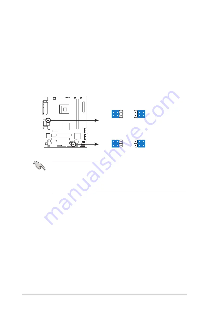
USB device wake-up

3

2

2

1

+5V

(Default)

+5VSB

USBPW78
USBPW56

3

2

2

1

+5V

(Default)

+5VSB

USBPW34
USBPW12

2 .

2 .

2 .

2 .

2 .

U S B   d e v i c e   w a k e - u p   ( 3 - p i n   U S B P W 1 2 ,   U S B P W 3 4 ,

U S B   d e v i c e   w a k e - u p   ( 3 - p i n   U S B P W 1 2 ,   U S B P W 3 4 ,

U S B   d e v i c e   w a k e - u p   ( 3 - p i n   U S B P W 1 2 ,   U S B P W 3 4 ,

U S B   d e v i c e   w a k e - u p   ( 3 - p i n   U S B P W 1 2 ,   U S B P W 3 4 ,

U S B   d e v i c e   w a k e - u p   ( 3 - p i n   U S B P W 1 2 ,   U S B P W 3 4 ,
U S B P W 5 6 ,   U S B P W 7 8 )

U S B P W 5 6 ,   U S B P W 7 8 )

U S B P W 5 6 ,   U S B P W 7 8 )

U S B P W 5 6 ,   U S B P W 7 8 )

U S B P W 5 6 ,   U S B P W 7 8 )
Set these jumpers to +5V to wake up the computer from S1 sleep
mode (CPU stopped, DRAM refreshed, system running in low power
mode) using the connected USB devices. Set to +5VSB to wake up
from S3 and S4 sleep modes (no power to CPU, DRAM in slow refresh,
power supply in reduced power mode).

The USBPWR12 and USBPWR34 jumpers are for the rear USB ports.
The USBPWR56 and USBPWR78 jumper is for the internal USB
connectors that you can connect to additional USB ports.

The USB device wake-up feature requires a power supply that can
provide 500mA on the +5VSB lead for each USB port; otherwise,
the system would not power up.

The total current consumed must NOT exceed the power supply
capability (+5VSB) whether under normal condition or in sleep mode.

Содержание Vintage-AE1

Страница 1: ...Vintage AE1 Barebone System ...

Страница 2: ...ANTIES OR CONDITIONS OF MERCHANTABILITY OR FITNESS FOR A PARTICULAR PURPOSE IN NO EVENT SHALL ASUS ITS DIRECTORS OFFICERS EMPLOYEES OR AGENTS BE LIABLE FOR ANY INDIRECT SPECIAL INCIDENTAL OR CONSEQUENTIAL DAMAGES INCLUDING DAMAGES FOR LOSS OF PROFITS LOSS OF BUSINESS LOSS OF USE OR DATA INTERRUPTION OF BUSINESS AND THE LIKE EVEN IF ASUS HAS BEEN ADVISED OF THE POSSIBILITY OF SUCH DAMAGES ARISING F...

Страница 3: ...ation 2 2 2 2 Before you proceed 2 2 2 3 Removing the side plates and front cover 2 3 2 4 Central Processing Unit CPU 2 5 2 4 1 Overview 2 5 2 4 2 Installling the CPU 2 5 2 4 3 Installing the heatsink and fan 2 7 2 5 Installing a DIMM 2 10 2 5 1 Memory configurations 2 10 2 5 2 Installing a DIMM 2 11 2 5 3 Removing a DIMM 2 11 2 6 Expansion slots 2 12 2 6 1 Installing an expansion card 2 12 2 6 2 ...

Страница 4: ...t 4 2 4 3 Jumpers 4 3 4 4 Connectors 4 5 Chapter 5 Chapter 5 Chapter 5 Chapter 5 Chapter 5 BIOS Information BIOS Information BIOS Information BIOS Information BIOS Information 5 1 Managing and updating your BIOS 5 2 5 1 1 Creating a bootable floppy disk 5 2 5 1 2 ASUS EZ Flash utility 5 3 5 1 3 AFUDOS utility 5 4 5 1 4 ASUS CrashFree BIOS 2 utility 5 6 5 1 5 ASUS Update utility 5 8 5 2 BIOS setup ...

Страница 5: ... 5 17 5 4 2 Chipset 5 18 5 4 3 Onboard Devices Configuration 5 21 5 4 4 PCI PnP 5 24 5 5 Power menu 5 26 5 5 1 Suspend Mode 5 26 5 5 2 Repost Video on S3 Resume 5 26 5 5 3 ACPI 2 0 Support 5 26 5 5 4 ACPI APIC Support 5 26 5 5 5 APM Configuration 5 27 5 5 6 Hardware Monitor 5 28 5 6 Boot menu 5 29 5 6 1 Boot Device Priority 5 30 5 6 2 Boot Settings Configuration 5 30 5 6 3 Security 5 32 5 7 Exit m...

Страница 6: ...ry to correct the interference by one or more of the following measures Reorient or relocate the receiving antenna Increase the separation between the equipment and receiver Connect the equipment to an outlet on a circuit different from that to which the receiver is connected Consult the dealer or an experienced radio TV technician for help Canadian Department of Communications Statement Canadian ...

Страница 7: ...ay from connectors slots sockets and circuitry Avoid dust humidity and temperature extremes Do not place the product in any area where it may become wet Place the product on a stable surface If you encounter technical problems with the product contact a qualified service technician or your retailer Lithium Ion Battery Warning Lithium Ion Battery Warning Lithium Ion Battery Warning Lithium Ion Batt...

Страница 8: ...hapter 2 Basic installation Chapter 2 Basic installation Chapter 2 Basic installation Chapter 2 Basic installation Chapter 2 Basic installation This chapter provides step by step instructions on how to install components in the system 3 3 3 3 3 Chapter 3 Starting up Chapter 3 Starting up Chapter 3 Starting up Chapter 3 Starting up Chapter 3 Starting up This chapter helps you power up the system an...

Страница 9: ...completing a task Where to find more information Where to find more information Where to find more information Where to find more information Where to find more information Refer to the following sources for additional information and for product and software updates 1 1 1 1 1 ASUS Websites ASUS Websites ASUS Websites ASUS Websites ASUS Websites The ASUS websites worldwide provide updated informat...

Страница 10: ...ription 1 1 1 1 1 ASUS Vintage AE1 barebone system ASUS Vintage AE1 barebone system ASUS Vintage AE1 barebone system ASUS Vintage AE1 barebone system ASUS Vintage AE1 barebone system with ASUS motherboard 250 W PFC power supply unit ASUS chassis 2 2 2 2 2 C a b l e C a b l e C a b l e C a b l e C a b l e AC power cable 3 3 3 3 3 Support CD Support CD Support CD Support CD Support CD 4 4 4 4 4 User...

Страница 11: ...e AE1 ASUS Vintage AE1 ASUS Vintage AE1 Chapter 1 System introduction This chapter gives a general description of the ASUS Vintage AE1 The chapter lists the system features including introduction on the front and rear panel and internal components ...

Страница 12: ...rboard that supports the AMD Athlon 64FX and Athlon 64 desktop processors Combined with the SIS 760GX chipset to set a new benchmark for an effective desktop platform solution The system supports up to 2GB of system memory using DDR400 333 266 DIMMs high resolution graphics via integrated graphics controller or AGP 8X slot Serial ATA RAID USB 2 0 and 6 channel audio features the system takes you a...

Страница 13: ...k 4 4 4 4 4 Reset button Reset button Reset button Reset button Reset button Press this button to reboot the system without turning off the power 5 5 5 5 5 Power button Power button Power button Power button Power button Press this button to turn the system on 6 6 6 6 6 Headphone port Headphone port Headphone port Headphone port Headphone port This Line In green port connects a headphone with a st...

Страница 14: ...Parallel port This 25 pin port connects a printer scanner or other devices 5 5 5 5 5 VGA port VGA port VGA port VGA port VGA port This port connects a VGA monitor 6 6 6 6 6 USB 2 0 ports 1 2 3 and 4 USB 2 0 ports 1 2 3 and 4 USB 2 0 ports 1 2 3 and 4 USB 2 0 ports 1 2 3 and 4 USB 2 0 ports 1 2 3 and 4 These 4 pin Universal Serial Bus USB ports are available for connecting USB 2 0 devices 7 7 7 7 7...

Страница 15: ...you to turn ON or OFF the flow of power to the power supply unit 14 14 14 14 14 Chassis fan vent Chassis fan vent Chassis fan vent Chassis fan vent Chassis fan vent This vent is for the fan that provides ventilation inside the system chassis 15 15 15 15 15 LAN RJ 45 port LAN RJ 45 port LAN RJ 45 port LAN RJ 45 port LAN RJ 45 port This port allows Gigabit connection to a Local Area Network LAN thro...

Страница 16: ... the power connector Use this switch to select the appropriate system input voltage according to the voltage supply in your area If the voltage supply in your area is 100 127 V set this switch to 115 V If the voltage supply in your area is 200 240 V set this switch to 230 V Setting the switch to 115V in a 230V environment or 230V in a 115V environment will seriously damage the system 115V 230V 115...

Страница 17: ...em when you remove the top cover and the power supply unit The installed components are labeled for your reference Proceed to Chapter 2 for instructions on installing additional system components 2 2 2 2 2 3 3 3 3 3 6 6 6 6 6 9 9 9 9 9 8 8 8 8 8 5 5 5 5 5 7 7 7 7 7 1 1 1 1 1 1 1 1 1 1 1 1 1 1 14 4 4 4 4 1 1 1 1 15 5 5 5 5 1 2 1 2 1 2 1 2 1 2 1 1 1 1 16 6 6 6 6 1 1 1 1 1 1 1 1 1 13 3 3 3 3 1 0 1 0 ...

Страница 18: ...1 8 1 8 1 8 1 8 1 8 Chapter 1 System introduction Chapter 1 System introduction Chapter 1 System introduction Chapter 1 System introduction Chapter 1 System introduction ...

Страница 19: ...SUS Vintage AE1 ASUS Vintage AE1 ASUS Vintage AE1 ASUS Vintage AE1 ASUS Vintage AE1 Chapter 2 Basic installation This chapter provides step by step instructions on how to install components in the system ...

Страница 20: ...motherboard comes with an onboard standby power LED This LED lights up to indicate that the system is ON in sleep mode or in soft off mode and not powered OFF Unplug the power cable from the power outlet and make sure that the standby power LED is OFF before installing any system component Use a grounded wrist strap or touch a safely grounded object or a metal object such as the power supply case ...

Страница 21: ...e chassis side plate 1 Turn each screw counterclockwise to release the side cover Set the screws aside 2 Slide the side panel for about half an inch toward the rear until it disengages from the chassis 3 Repeat steps 1 and 2 to remove the other side plate cover 3 Release the side lock tabs from the steel railing Screw Side lock tab Side lock tab Side lock tab Side lock tab Side lock tab Steel rail...

Страница 22: ...2 Basic installation Chapter 2 Basic installation 4 Swing the left edge of the front panel outward 5 Unhook the hinge like tabs from the holes on the right side of the front panel to completely detach the front panel assembly from the chassis Hinge like tab Hinge like tab Hinge like tab Hinge like tab Hinge like tab ...

Страница 23: ...ever is on your left 2 4 Central Processing Unit CPU 2 4 1 2 4 1 2 4 1 2 4 1 2 4 1 Overview Overview Overview Overview Overview The motherboard comes with a surface mount 754 pin Zero Insertion Force ZIF socket designed for the AMD Athlon 64 or AMD Sempron processor The 128 bit wide data paths of these processors can run applications faster than processors with only 32 bit or 64 bit wide data path...

Страница 24: ...then lift it up to a 90 100 angle Make sure that the socket lever is lifted up to 90 100 angle otherwise the CPU does not fit in completely The CPU fits only in one correct orientation DO NOT force the CPU into the socket to prevent bending the pins and damaging the CPU 5 When the CPU is in place push down the socket lever to secure the CPU The lever clicks on the side tab to indicate that it is l...

Страница 25: ...Base CPU Heatsink CPU Heatsink CPU Heatsink CPU Heatsink CPU Heatsink CPU Fan CPU Fan CPU Fan CPU Fan CPU Fan Retention bracket lock Retention bracket lock Retention bracket lock Retention bracket lock Retention bracket lock Retention bracket Retention bracket Retention bracket Retention bracket Retention bracket The retention module base is already installed on the motherboard upon purchase You d...

Страница 26: ... Align the other end of the retention bracket near the retention bracket lock to the retention module base A clicking sound denotes that the retention bracket is in place 4 Push down the retention bracket lock on the retention mechanism to secure the heatsink and fan to the module base Make sure that the fan and heatsink assembly perfectly fits the retention mechanism module base otherwise you can...

Страница 27: ...tage AE1 3 When the fan and heatsink assembly is in place connect the CPU fan cable to the connector on the motherboard labeled CPU_FAN Do not forget to connect the CPU fan connector Hardware monitoring errors can occur if you fail to plug this connector CPU_FAN GND Rotation 12V CPU fan connector ...

Страница 28: ...tical identical the same type and size DDR memory modules Install only ASUS certified memory modules Visit the ASUS website www asus com for the latest memory Qualified Vendors List Always install DIMMs with the same CAS latency For optimum compatibility we recommend that you obtain memory modules from the same vendor 2 5 1 2 5 1 2 5 1 2 5 1 2 5 1 Memory configurations Memory configurations Memory...

Страница 29: ...n place and the DIMM is properly seated 1 Unlock a DIMM socket by pressing the retaining clips outward 2 Align a DIMM on the socket such that the notch on the DIMM matches the break on the socket Locked Retaining Clip Locked Retaining Clip Locked Retaining Clip Locked Retaining Clip Locked Retaining Clip Make sure to unplug the power supply before adding or removing DIMMs or other system component...

Страница 30: ...hassis 3 Remove the bracket opposite the slot that you intend to use Keep the screw for later use 4 Align the card connector with the slot and press firmly until the card is completely seated on the slot 5 Secure the card to the chassis with the screw you removed earlier 6 Replace the system cover Make sure to unplug the power cord before adding or removing expansion cards Failure to do so may cau...

Страница 31: ...These IRQs are usually available for ISA or PCI devices These IRQs are usually available for ISA or PCI devices These IRQs are usually available for ISA or PCI devices These IRQs are usually available for ISA or PCI devices These IRQs are usually available for ISA or PCI devices IRQ assignments for this motherboard IRQ assignments for this motherboard IRQ assignments for this motherboard IRQ assig...

Страница 32: ...supports AGP8X 4X cards When you buy an AGP card make sure that you ask for one with 1 5V specification Note the notches on the card golden fingers to ensure that they fit the AGP slot on your motherboard Accelerated Graphics Port AGP Keyed for 1 5v 2 6 3 2 6 3 2 6 3 2 6 3 2 6 3 PCI Express x1 slot PCI Express x1 slot PCI Express x1 slot PCI Express x1 slot PCI Express x1 slot This motherboard sup...

Страница 33: ... acquired a model without an optical drive Follow these steps to install an optical drive 1 Place the chassis upright 2 Insert the optical drive into the upper 5 25 inch drive bay Screw holes Screw holes Screw holes Screw holes Screw holes 3 Carefully push the optical drive into the bay until its screw holes align with the holes on the bay as shown 4 Secure the optical drive with two screws on bot...

Страница 34: ...e to the 4 pin connector at the back of the optical drive Red stripe to pin 1 Red stripe to pin 1 Red stripe to pin 1 Red stripe to pin 1 Red stripe to pin 1 IDE ribbon cable IDE ribbon cable IDE ribbon cable IDE ribbon cable IDE ribbon cable Power cable Power cable Power cable Power cable Power cable Audio cable Audio cable Audio cable Audio cable Audio cable 8 Connect the other end of the IDE ri...

Страница 35: ...e the chassis upright 2 With the HDD label side up carefully insert the drive into the 3 5 inch bay 3 Push the drive into the bay until its screw holes align with the holes on the drive bay HDD screw holes HDD screw holes HDD screw holes HDD screw holes HDD screw holes 4 Secure the drive with two screws on both sides 5 Connect one end of the Serial ATA cable to the SATA connector at the back of th...

Страница 36: ...nstall an IDE hard disk drive 1 Follow steps 1 4 of the previous section If you will install only one hard disk drive make sure to configure your hard disk drive as Master device before connecting the IDE cable and power plug Refer to the HDD documentation on how to set the drive as a Master device If you will install two IDE hard disk drives configure the other device as Slave 3 2 2 Connect the b...

Страница 37: ...page 2 3 of section 2 3 Removing the side plates and front cover 2 Carefully insert the floppy disk drive into the floppy drive bay until the screw holes align with the holes on the bay 3 Secure the floppy disk drive with two screws 4 Connect the floppy disk drive signal cable to the signal connector at the back of the drive 5 Connect the other end of the signal cable to the floppy disk drive conn...

Страница 38: ...ED Ground RESET Ground Reset Ground Ground PLED IDELED 5V IDE_LED PWRSW SPEAKER PANEL Connect the reset button power switch reset button power switch reset button power switch reset button power switch reset button power switch power LED power LED power LED power LED power LED and HDD HDD HDD HDD HDD LED LED LED LED LED cables to their respective leads in the system panel connector on the motherbo...

Страница 39: ...re now ready to put the system back together 1 Hook the hinge like tabs to the holes on the right side of the front panel to attach the front panel assembly to the chassis 2 Swing the front panel inward Hinge like tab Hinge like tab Hinge like tab Hinge like tab Hinge like tab 3 Snap the side lock tabs to the steel railing Side lock tab Side lock tab Side lock tab Side lock tab Side lock tab Steel...

Страница 40: ...e plate from the rear until it fits the chassis completely The locking tabs snap into the hole on the chassis to indicate that the side plate is in place S c r e w S c r e w S c r e w S c r e w S c r e w 6 Lock the side plate with the screws on the rear panel 7 Repeat steps 4 5 and 6 to replace the other side plate cover Locking Locking Locking Locking Locking tab hole tab hole tab hole tab hole t...

Страница 41: ...ASUS Vintage AE1 ASUS Vintage AE1 ASUS Vintage AE1 2 12 Connecting external devices The figure below shows the specific connectors and devices that you can connect to the rear panel ports Serial PS 2 KB VGA Line Out Line In Mic PS 2 Mouse AC Parallel USB RJ 45 ...

Страница 42: ...2 24 2 24 2 24 2 24 2 24 Chapter 2 Basic installation Chapter 2 Basic installation Chapter 2 Basic installation Chapter 2 Basic installation Chapter 2 Basic installation ...

Страница 43: ...SUS Vintage AE1 ASUS Vintage AE1 ASUS Vintage AE1 ASUS Vintage AE1 ASUS Vintage AE1 Chapter 3 Starting up This chapter helps you power up the system and install drivers and utilities from the support CD ...

Страница 44: ...nce the system features 3 2 Powering up The system has two power buttons located in the front panel Press the system power button to enter the OS Press to turn ON the system Press to turn ON the system Press to turn ON the system Press to turn ON the system Press to turn ON the system Because motherboard settings and hardware options vary use the setup procedures presented in this chapter for gene...

Страница 45: ...splay support display support display support display support display support CD motherboard CD motherboard CD motherboard CD motherboard CD motherboard information information information information information AGP SiS 760 driver AGP SiS 760 driver AGP SiS 760 driver AGP SiS 760 driver AGP SiS 760 driver Installs the SiS 760 AGP driver SIS 760 Graphics Driver SIS 760 Graphics Driver SIS 760 Grap...

Страница 46: ...logy drivers USB 2 0 Driver USB 2 0 Driver USB 2 0 Driver USB 2 0 Driver USB 2 0 Driver Installs the USB 2 0 driver to upgrade your USB 1 1 ports to USB 2 0 For Windows XP users make sure to install Windows XP SP 1 to support USB 2 0 ASUS AMD Cool n Quiet Software ASUS AMD Cool n Quiet Software ASUS AMD Cool n Quiet Software ASUS AMD Cool n Quiet Software ASUS AMD Cool n Quiet Software Installs th...

Страница 47: ...Screen Saver ASUS Screen Saver ASUS Screen Saver ASUS Screen Saver ASUS Screen Saver Installs the ASUS screen saver 3 3 3 3 3 3 3 3 3 3 3 3 3 3 3 Manuals menu Manuals menu Manuals menu Manuals menu Manuals menu The Manuals menu contains a list of supplementary user manuals Click an item to open the folder of the user manual Most user manual files are in Portable Document Format PDF Install the Ado...

Страница 48: ...p 3 3 4 3 3 4 3 3 4 3 3 4 3 3 4 ASUS Contact information ASUS Contact information ASUS Contact information ASUS Contact information ASUS Contact information Click the Contact Contact Contact Contact Contact tab to display the ASUS contact information You can also find this information on the inside front cover of this user guide ...

Страница 49: ...S Vintage AE1 ASUS Vintage AE1 ASUS Vintage AE1 Chapter 4 Motherboard info This chapter gives information about the motherboard that comes with the system This chapter includes the motherboard layout jumper settings and connector locations ...

Страница 50: ... Motherboard layout PANEL FLOPPY SEC_IDE SIS 965L 4M BIOS ATX12V SIS 760GX AUX CPU_FAN CD CHA_FAN 19 9cm 7 8in 24 4cm 9 6in Super I O GAME PCI1 AD1888 Below Mic In Center Line Out Top Line In CHASSIS PCI2 PCIEX1_1 PARALLEL PORT COM1 VGA PS 2KBMS T Mouse B Keyboard USB12 USB78 FP_AUDIO DDR DIMM2 64 bit 184 pin module DDR DIMM1 64 bit 184 pin module USBPW56 USBPW34 USBPW12 SB_PWR Top RJ 45 Bottom US...

Страница 51: ...in the CMOS which includes the system setup information such as system passwords To erase the RTC RAM 1 Turn OFF the computer and unplug the power cord 2 Remove the battery 3 Move the jumper cap from pins 1 2 default to pins 2 3 Keep the cap on pins 2 3 for about 5 10 seconds then move the cap back to pins 1 2 4 Re install the battery 5 Plug the power cord and turn ON the computer 6 Hold down the ...

Страница 52: ...6 USBPW78 Set these jumpers to 5V to wake up the computer from S1 sleep mode CPU stopped DRAM refreshed system running in low power mode using the connected USB devices Set to 5VSB to wake up from S3 and S4 sleep modes no power to CPU DRAM in slow refresh power supply in reduced power mode The USBPWR12 and USBPWR34 jumpers are for the rear USB ports The USBPWR56 and USBPWR78 jumper is for the inte...

Страница 53: ...ntation for the jumper settings Pin 20 on the IDE connector is removed to match the covered hole on the Ultra DMA cable connector This prevents incorrect insertion when you connect the IDE cable Use the 80 conductor IDE cable for Ultra DMA 100 66 IDE devices 1 1 1 1 1 Floppy disk drive connector 34 1 pin FLOPPY Floppy disk drive connector 34 1 pin FLOPPY Floppy disk drive connector 34 1 pin FLOPPY...

Страница 54: ...ide the system may damage the motherboard components These are not jumpers Do not place jumper caps on the fan connectors 3 3 3 3 3 Serial ATA connectors 7 pin SATA1 SATA2 Serial ATA connectors 7 pin SATA1 SATA2 Serial ATA connectors 7 pin SATA1 SATA2 Serial ATA connectors 7 pin SATA1 SATA2 Serial ATA connectors 7 pin SATA1 SATA2 These connectors are for the Serial ATA signal cables for Serial ATA...

Страница 55: ...SB connectors 10 1 pin USB56 USB78 USB connectors 10 1 pin USB56 USB78 USB connectors 10 1 pin USB56 USB78 USB connectors 10 1 pin USB56 USB78 USB connectors 10 1 pin USB56 USB78 These connectors are for USB 2 0 ports Connect the USB GAME module cable to any of these connectors then install the module to a slot opening at the back of the system chassis These USB connectors comply with USB 2 0 spec...

Страница 56: ...the optical drive Enable the CD IN function in the audio utility when using this connector 8 8 8 8 8 Front panel audio connector 10 1 pin FP_AUDIO Front panel audio connector 10 1 pin FP_AUDIO Front panel audio connector 10 1 pin FP_AUDIO Front panel audio connector 10 1 pin FP_AUDIO Front panel audio connector 10 1 pin FP_AUDIO This connector is for a chassis mounted front panel audio I O module ...

Страница 57: ...hassis intrusion event By default the pins labeled Chassis Signal and Ground are shorted with a jumper cap Remove the jumper caps only when you intend to use the chassis intrusion detection feature Chassis intrusion connector CHASSIS 5VSB_MB Chassis Signal GND Default R Game connector GAME 5V 5V J2B1 J2CX MIDI_OUT J2CY J2B2 MIDI_IN J1B1 J1CX GND GND J1CY J1B2 5V 10 10 10 10 10 GAME MIDI port conne...

Страница 58: ...PEAKER PANEL 11 11 11 11 11 Digital audio connector 4 1 pin SPDIF_OUT Digital audio connector 4 1 pin SPDIF_OUT Digital audio connector 4 1 pin SPDIF_OUT Digital audio connector 4 1 pin SPDIF_OUT Digital audio connector 4 1 pin SPDIF_OUT This connector is for an additional Sony Philips Digital Interface S PDIF port s Connect the S PDIF module cable to this connector then install the module to a sl...

Страница 59: ...y LED Connect the HDD Activity LED cable to this connector The IDE LED lights up or flashes when data is read from or written to the HDD ATX power button soft off button Yellow 2 pin PWRSW ATX power button soft off button Yellow 2 pin PWRSW ATX power button soft off button Yellow 2 pin PWRSW ATX power button soft off button Yellow 2 pin PWRSW ATX power button soft off button Yellow 2 pin PWRSW Thi...

Страница 60: ...4 12 4 12 4 12 4 12 4 12 Chapter 4 Motherboard info Chapter 4 Motherboard info Chapter 4 Motherboard info Chapter 4 Motherboard info Chapter 4 Motherboard info ...

Страница 61: ...ntage AE1 ASUS Vintage AE1 ASUS Vintage AE1 ASUS Vintage AE1 ASUS Vintage AE1 Chapter 5 BIOS setup This chapter tells how to change system settings through the BIOS Setup menus and describes the BIOS parameters ...

Страница 62: ... to create a bootable floppy disk DOS environment a Insert a 1 44MB floppy disk into the drive b At the DOS prompt type format A S then press Enter Windows XP environment a Insert a 1 44 MB floppy disk to the floppy disk drive b Click Start Start Start Start Start from the Windows desktop then select M y M y M y M y M y Computer Computer Computer Computer Computer c Select the 3 1 2 Floppy Drive i...

Страница 63: ...ebsite www asus com to download the latest BIOS file for the motherboard and rename the same to K8SMV V ROM K8SMV V ROM K8SMV V ROM K8SMV V ROM K8SMV V ROM 2 Save the BIOS file to a floppy disk then restart the system 3 Press Alt F2 during POST to display the following EZFlash starting BIOS update Checking for floppy 4 Insert the floppy disk that contains the BIOS file to the floppy disk drive Whe...

Страница 64: ...ess Enter The utility copies the current BIOS file to the floppy disk A afudos oOLDBIOS1 ROM AMI Firmware Update Utility Version 1 10 Copyright C 2002 American Megatrends Inc All rights reserved Reading flash done A Main filename Main filename Main filename Main filename Main filename Extension name Extension name Extension name Extension name Extension name 1 Copy the AFUDOS utility afudos exe fr...

Страница 65: ...utility 1 Visit the ASUS website www asus com and download the latest BIOS file for the motherboard Save the BIOS file to a bootable floppy disk 4 The utility reads the file and starts updating the BIOS Do not shut down or reset the system while updating the BIOS to prevent system boot failure Write the BIOS filename on a piece of paper You need to type the exact BIOS filename at the DOS prompt A ...

Страница 66: ...CrashFree BIOS 2 utility ASUS CrashFree BIOS 2 utility The ASUS CrashFree BIOS 2 is an auto recovery tool that allows you to restore the BIOS file when it fails or gets corrupted during the updating process You can update a corrupted BIOS file using the motherboard support CD or the floppy disk that contains the updated BIOS file Recovering the BIOS from a floppy disk Recovering the BIOS from a fl...

Страница 67: ...cking for CD ROM CD ROM found Reading file K8SMV V ROM Completed Start flashing When no floppy disk is found the utility automatically checks the optical drive for the original or updated BIOS file The utility then updates the corrupted BIOS file Bad BIOS checksum Starting BIOS recovery Checking for floppy Bad BIOS checksum Starting BIOS recovery Checking for floppy 4 Restart the system after the ...

Страница 68: ...pdate Install ASUS Update Install ASUS Update Install ASUS Update VX XX XX VX XX XX VX XX XX VX XX XX VX XX XX See page 3 4 for the Utilities Utilities Utilities Utilities Utilities screen menu 3 The ASUS Update utility is copied to your system 5 1 5 5 1 5 5 1 5 5 1 5 5 1 5 ASUS Update utility ASUS Update utility ASUS Update utility ASUS Update utility ASUS Update utility The ASUS Update is a util...

Страница 69: ...et Updating the BIOS through the Internet To update the BIOS through the Internet 1 Launch the ASUS Update utility from the Windows desktop by clicking Start Start Start Start Start Programs Programs Programs Programs Programs ASUS ASUS ASUS ASUS ASUS ASUSUpdate ASUSUpdate ASUSUpdate ASUSUpdate ASUSUpdate ASUSUpdate ASUSUpdate ASUSUpdate ASUSUpdate ASUSUpdate The ASUS Update main window appears 2 ...

Страница 70: ...SUSUpdate ASUSUpdate ASUSUpdate ASUSUpdate ASUSUpdate ASUSUpdate ASUSUpdate ASUSUpdate The ASUS Update main window appears 2 Select Update BIOS from a Update BIOS from a Update BIOS from a Update BIOS from a Update BIOS from a file file file file file option from the drop down menu then click Next Next Next Next Next 4 From the FTP site select the BIOS version that you wish to download Click Next ...

Страница 71: ...s Del during the Power On Self Test POST to enter the Setup utility otherwise POST continues with its test routines If you wish to enter Setup after POST restart the system by pressing Ctrl Alt Delete or by pressing the reset button on the system chassis You can also restart by turning the system off and then back on Do this last option only if the first two failed The Setup program is designed to...

Страница 72: ... Some of the navigation keys differ from one screen to another 5 2 3 5 2 3 5 2 3 5 2 3 5 2 3 Navigation keys Navigation keys Navigation keys Navigation keys Navigation keys At the bottom right corner of a menu screen are the navigation keys for that particular menu Use the navigation keys to select items in the menu and change the settings System Time 11 51 19 System Date Thu 10 07 2004 Legacy Dis...

Страница 73: ... item 5 2 8 5 2 8 5 2 8 5 2 8 5 2 8 Scroll bar Scroll bar Scroll bar Scroll bar Scroll bar A scroll bar appears on the right side of a menu screen when there are items that do not fit on the screen Press the Up Down arrow keys or Page Up Page Down keys to display the other items on the screen 5 2 9 5 2 9 5 2 9 5 2 9 5 2 9 General help General help General help General help General help At the top ...

Страница 74: ... xxxx Allows you to set the system date 5 3 3 5 3 3 5 3 3 5 3 3 5 3 3 Legacy Diskette A 1 44M 3 5 in Legacy Diskette A 1 44M 3 5 in Legacy Diskette A 1 44M 3 5 in Legacy Diskette A 1 44M 3 5 in Legacy Diskette A 1 44M 3 5 in Sets the type of floppy drive installed Configuration options Disabled 360K 5 25 in 1 2M 5 25 in 720K 3 5 in 1 44M 3 5 in 2 88M 3 5 in Refer to section 5 2 1 BIOS menu screen ...

Страница 75: ...ROM drive Select ARMD ATAPI Removable Media Device if your device is either a ZIP LS 120 or MO drive Configuration options Not Installed Auto CDROM ARMD LBA Large Mode Auto LBA Large Mode Auto LBA Large Mode Auto LBA Large Mode Auto LBA Large Mode Auto Enables or disables the LBA mode Setting to Auto enables the LBA mode if the device supports this mode and if the device was not previously formatt...

Страница 76: ...bit data transfer Configuration options Disabled Enabled AMI BIOS AMI BIOS AMI BIOS AMI BIOS AMI BIOS Displays the auto detected BIOS information Processor Processor Processor Processor Processor Displays the auto detected CPU specification System Memory System Memory System Memory System Memory System Memory Displays the auto detected system memory AMIBIOS Version 0201 Build Date 03 30 05 Process...

Страница 77: ...ol N Quiet Enabled Cool N Quiet Enabled Cool N Quiet Enabled Cool N Quiet Enabled Enables or disables the AMD Cool n Quiet technology Configuration options Disabled Enabled CPU Configuration Cool N Quiet Enabled Memory Configuration 5 4 Advanced menu The Advanced menu items allow you to change the settings for the CPU and other system devices Take caution when changing the settings of the Advanced...

Страница 78: ...o Limit Memclock Value 100MHz Sets the memory clock value This item appears only when the Memclock Mode item is set to Limit Configuration options 100MHz 133MHz 166MHz 200 MHz 5 4 2 5 4 2 5 4 2 5 4 2 5 4 2 Chipset Chipset Chipset Chipset Chipset The Chipset menu items allow you to change the advanced chipset settings Select an item then press Enter to display the sub menu Chipset Settings AGP Conf...

Страница 79: ...4MB Allows you to set the size of mapped memory for AGP graphic data Configuration options 32MB 64MB 128MB Graphic Adapter Priority AGP Int VGA Allows you to select the primary graphics boot device Configuration options Internal VGA AGP Int VGA AGP PCI PCI AGP PCI Int VGA AGP FAST WRITE Disabled Enables or disables the AGP Fast Write feature Configuration options Disabled Enabled Select AGP 3 0 Da...

Страница 80: ... Width 8x16 BIT Sets the HyperTransport data width Configuration options 8x8 BIT 16x16 BIT 16x8 BIT 8x16 BIT HT Speed 800 MHz Sets the HyperTransport data speed Configuration options 200 MHz 400 MHz 600 MHz 800 MHz HyperTransport Configuration HT Width 8x16 BIT HT Speed 800 MHz MPS Configuration MPS Configuration MPS Configuration MPS Configuration MPS Configuration MPS Configuration MPS Revision ...

Страница 81: ... Disabled Enabled USB Configuration USB Configuration USB Configuration USB Configuration USB Configuration The items in this menu allows you to change the USB related features Select an item then press Enter to display the configuration options 5 4 3 5 4 3 5 4 3 5 4 3 5 4 3 Onboard Devices Configuration Onboard Devices Configuration Onboard Devices Configuration Onboard Devices Configuration Onbo...

Страница 82: ...ce is detected the legacy USB support is disabled Configuration options Disabled Enabled Auto USB 2 0 Controller Mode HiSpeed Allows you to configure the USB 2 0 controller in HiSpeed 480 Mbps or Full Speed 12 Mbps Configuration options HiSpeed Full Speed Stop EHCI HC in OHCI handover Enabled Allows you to enable or disable the feature to stop the EHCI host controller during the OHCI OS handover c...

Страница 83: ...t Parallel Port Parallel Port Parallel Port Parallel Port Address Address Address Address Address is set to 3BC 3BC 3BC 3BC 3BC the Parallel Port Mode options are only Normal Bi directional and ECP Configuration options Normal Bi directional EPP ECP ECP Mode DMA Channel DMA3 Allows selection of the Parallel Port ECP DMA channel This item appears only when the Parallel Port Mode Parallel Port Mode ...

Страница 84: ...lay O S No Plug and Play O S No Plug and Play O S No When set to No BIOS configures all the devices in the system When set to Yes and if you install a Plug and Play operating system the operating system configures the Plug and Play devices not required for boot Configuration options No Yes PCI Latency Timer 64 PCI Latency Timer 64 PCI Latency Timer 64 PCI Latency Timer 64 PCI Latency Timer 64 Allo...

Страница 85: ... Card Auto OffBoard PCI ISA IDE Card Auto OffBoard PCI ISA IDE Card Auto OffBoard PCI ISA IDE Card Auto OffBoard PCI ISA IDE Card Auto Allows BIOS to use PCI bus mastering when reading writing to IDE devices Configuration options Auto PCI Slot IRQ xx assigned to PCI Device IRQ xx assigned to PCI Device IRQ xx assigned to PCI Device IRQ xx assigned to PCI Device IRQ xx assigned to PCI Device When s...

Страница 86: ...Resume No Repost Video on S3 Resume No Repost Video on S3 Resume No Detemines whether to invoke VGA BIOS POST on S3 STR resume Configuration options No Yes 5 5 3 5 5 3 5 5 3 5 5 3 5 5 3 ACPI 2 0 Support No ACPI 2 0 Support No ACPI 2 0 Support No ACPI 2 0 Support No ACPI 2 0 Support No Allows you to add more tables for Advanced Configuration and Power Interface ACPI 2 0 specifications Configuration...

Страница 87: ...ss Power Off When set to Power Off the system goes into off state after an AC power loss When set to Power On the system goes on after an AC power loss When set to Last State the system goes into either off or on state whatever the system state was before the AC power loss Configuration options Power Off Power On Last State Resume On Ring Disabled Resume On Ring Disabled Resume On Ring Disabled Re...

Страница 88: ...ows N A Select Ignored if you do not wish to display the detected fan speed CPU Temperature xxxºC xxxºF CPU Temperature xxxºC xxxºF CPU Temperature xxxºC xxxºF CPU Temperature xxxºC xxxºF CPU Temperature xxxºC xxxºF MB Temperature xxxºC xxxºF MB Temperature xxxºC xxxºF MB Temperature xxxºC xxxºF MB Temperature xxxºC xxxºF MB Temperature xxxºC xxxºF The onboard hardware monitor automatically detect...

Страница 89: ...eed Temperature 40 Degree CPU Full Speed Temperature 40 Degree CPU Full Speed Temperature 40 Degree CPU Full Speed Temperature 40 Degree CPU Full Speed Temperature 40 Degree Allows you to set the CPU temperature threshold when the CPU fan speed is increased to lower the CPU temperature Configuration options 10 Degree 13 Degree 16 Degree 20 Degree 26 Degree 32 Degree 40 Degree CPU Fan Min Duty Cycl...

Страница 90: ...t xxth Boot Device 1st Floppy Drive 1st xxth Boot Device 1st Floppy Drive 1st xxth Boot Device 1st Floppy Drive 1st xxth Boot Device 1st Floppy Drive These items specify the boot device priority sequence from the available devices The number of device items that appears on the screen depends on the number of devices installed in the system Configuration options 1st Floppy Drive xxxxx Drive Disable...

Страница 91: ...isable support for PS 2 mouse Configuration options Disabled Enabled Auto Wait for F1 If Error Enabled Wait for F1 If Error Enabled Wait for F1 If Error Enabled Wait for F1 If Error Enabled Wait for F1 If Error Enabled When set to Enabled the system waits for the F1 key to be pressed when error occurs Configuration options Disabled Enabled Hit DEL Message Display Enabled Hit DEL Message Display En...

Страница 92: ... Password Change Supervisor Password Change Supervisor Password Change Supervisor Password Change Supervisor Password Select this item to set or change the supervisor password The Supervisor Password item on top of the screen shows the default Not Installed Not Installed Not Installed Not Installed Not Installed After you set a password this item shows Installed Installed Installed Installed Insta...

Страница 93: ...Password Change User Password Change User Password Change User Password Change User Password Select this item to set or change the user password The User Password item on top of the screen shows the default Not Installed Not Installed Not Installed Not Installed Not Installed After you set a password this item shows Installed Installed Installed Installed Installed To set a User Password 1 Select ...

Страница 94: ...ndows XP Service Pack 2 or Windows 2003 Service Pack 1 or later to use this feature Configuration options Disabled Enabled Exit Save Changes Exit Save Changes Exit Save Changes Exit Save Changes Exit Save Changes Once you are finished making your selections choose this option from the Exit menu to ensure the values you selected are saved to the CMOS RAM An onboard backup battery sustains the CMOS ...

Страница 95: ...r selecting this option a confirmation appears Select Ok Ok Ok Ok Ok to discard any changes and load the previously saved values Load Setup Defaults Load Setup Defaults Load Setup Defaults Load Setup Defaults Load Setup Defaults This option allows you to load the default values for each of the parameters on the Setup menus When you select this option or if you press F5 a confirmation window appear...

Страница 96: ...5 36 5 36 5 36 5 36 5 36 Chapter 5 BIOS setup Chapter 5 BIOS setup Chapter 5 BIOS setup Chapter 5 BIOS setup Chapter 5 BIOS setup ...

Отзывы: