Asus TUF X470-PLUS GAMING Скачать руководство пользователя страница 42

2-12

Chapter 2: Basic Installation

C

h

ap
te

2

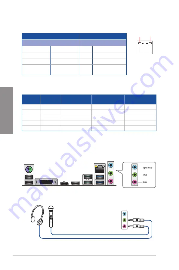
** Audio 2, 4, 6 or 8-channel con guration

Port

Headset 

2-channel

4-channel

6-channel

8-channel

Light Blue

Line In

Line In

Line In

Side Speaker Out

Lime

Line Out

Front Speaker Out

Front Speaker Out

Front Speaker Out

Pink

Mic In

Mic In

Mic In

Mic In

Orange

Center/Sub woofer

Center/Sub woofer

Black

Rear Speaker Out

Rear Speaker Out

Rear Speaker Out

2.2.2 

Audio I/O connections

Audio I/O ports

* LAN ports LED indications

SPEED 

LED

ACT/LINK 

LED

LAN port

Activity Link LED

Speed LED

Status

Description

Status

Description

Off

No link

Off

10 Mbps connection

Orange

Linked

Orange 100 Mbps connection

Orange (Blinking) Data activity

Green

1 Gbps connection

Orange (Blinking 
then steady)

Ready to wake up 
from S5 mode

Connect to Headphone and Mic

Содержание TUF X470-PLUS GAMING

Страница 1: ...Motherboard TUF X470 PLUS GAMING ...

Страница 2: ... respective companies and are used only for identi cation or explanation and to the owners bene t without intent to infringe Offer to Provide Source Code of Certain Software This product contains copyrighted software that is licensed under the General Public License GPL under the Lesser General Public License Version LGPL and or other Free Open Source Software Licenses Such software in this produc...

Страница 3: ... Building your PC system 2 1 2 1 1 Motherboard installation 2 1 2 1 2 CPU installation 2 3 2 1 3 CPU heatsink and fan assembly installation 2 4 2 1 4 DIMM installation 2 6 2 1 5 ATX power connection 2 7 2 1 6 SATA device connection 2 7 2 1 7 Front I O connector 2 8 2 1 8 Expansion card installation 2 9 2 1 9 M 2 installation 2 10 2 2 Motherboard rear and audio connections 2 11 2 2 1 Rear I O conne...

Страница 4: ...Network Stack Con guration 3 15 3 6 9 HDD SSD SMART Information 3 15 3 6 10 USB Con guration 3 15 3 7 Monitor menu 3 16 3 8 Boot menu 3 16 3 9 Tool menu 3 17 3 9 1 ASUS EZ Flash 3 Utility 3 17 3 9 2 ASUS User Pro le 3 18 3 9 3 ASUS SPD Information 3 18 3 10 Exit menu 3 18 3 11 Updating BIOS 3 19 3 11 1 EZ Update 3 19 3 11 2 ASUS EZ Flash 3 3 20 3 11 3 ASUS CrashFree BIOS 3 3 22 Chapter 4 RAID Supp...

Страница 5: ... your area If you are not sure about the voltage of the electrical outlet you are using contact your local power company If the power supply is broken do not try to x it by yourself Contact a quali ed service technician or your retailer Operation safety Before installing the motherboard and adding devices on it carefully read all the manuals that came with the package Before using the product ensu...

Страница 6: ...en installing system components Chapter 3 BIOS Setup This chapter tells how to change system settings through the BIOS Setup menus Detailed descriptions of the BIOS parameters are also provided Chapter 4 RAID Support This chapter describes the RAID con gurations Where to nd more information Refer to the following sources for additional information and for product and software updates 1 ASUS websit...

Страница 7: ...ete a task IMPORTANT Instructions that you MUST follow to complete a task NOTE Tips and additional information to help you complete a task Typography Bold text Indicates a menu or an item to select Italics Used to emphasize a word or a phrase Key Keys enclosed in the less than and greater than sign means that you must press the enclosed key Example Enter means that you must press the Enter or Retu...

Страница 8: ...de AMD Ryzen with Radeon Vega Graphics 7th Generation A Series Athlon X4 Processors 1 x PCIe 3 0 x16 slot max at x8 mode AMD X470 chipset 1 x PCIe 2 0 x16 slot max at x4 mode 3 x PCIe 2 0 x1 slots Graphics Integrated Graphics in the AMD Ryzen with Radeon Vega Graphics 7th Generation A Series Processors Multi VGA output support HDMI and DVI D ports Supports HDMI 1 4b with maximum resolution of 4096...

Страница 9: ...Vega Graphics Ryzen 1st Generation 7th Generation A Series Athlon X4 Processors 3 x USB 3 1 Gen 1 up to 5Gbps ports at back panel 2 x Type A and 1 x Type C AMD X470 chipset 2 x USB 3 1 Gen 2 up to 10Gbps ports at back panel teal blue 4 x USB 3 1 Gen 1 up to 5Gbps ports at mid board 6 x USB 2 0 ports at mid board 2 ports at back panel 4 ports at mid board ASUS Unique Features Dependable Stability A...

Страница 10: ...sink solution ASUS FAN Xpert 4 Core ASUS Exclusive Overclocking Features Precision Tweaker 2 vVDDCR CPU Adjustable CPU voltage at 0 00625V increment vVDDCR SOC Adjustable CPU NB voltage at 0 00625V increment vDRAM Bus Adjustable DRAM voltage at 0 005V increment Overclocking Protection ASUS C P R CPU Parameter Recall Back I O Ports 1 x PS 2 keyboard mouse combo port 1 x HDMI port 1 x DVI D port 2 x...

Страница 11: ...lers control with auto detection support 1 x AIO_PUMP connector 4 pin 1 x AURA RGB header 1 x 24 pin EATX power connector 1 x 8 pin EATX 12V power connector 1 x System panel connector 1 x Front panel audio connector AAFP 1 x COM connector 1 x S PDIF out connector 1 x Clear CMOS jumper 2 pin BIOS 256 Mb Flash ROM UEFI AMI BIOS PnP SM BIOS 3 0 ACPI 6 0 Multi language BIOS ASUS EZ Flash 3 CrashFree B...

Страница 12: ...rd TUF X470 PLUS GAMING Cables 2 x SATA 6 Gb s cables Accessories 1 x I O shield 1 x M 2 screw package 1 x TUF Gaming Sticker 1 x TUF Certi cation card Application DVD Motherboard support DVD Documentation User guide If any of the above items is damaged or missing contact your retailer ...

Страница 13: ... cross screwdriver PC chassis Power supply unit AMD AM4 CPU AMD AM4 AM3 compatible CPU Fan DDR4 DIMM SATA hard disk drive SATA optical disc drive optional Graphics card optional The tools and components in the table above are not included in the motherboard package ...

Страница 14: ...xiv ...

Страница 15: ...ents by the edges to avoid touching the ICs on them Whenever you uninstall any component place it on a grounded antistatic pad or in the bag that came with the component Before you install or remove any component ensure that the ATX power supply is switched off or the power cord is detached from the power supply Failure to do so may cause severe damage to the motherboard peripherals or components ...

Страница 16: ...M_B2 64bit 288 pin module AIO_PUMP CPU_FAN CHA_FAN2 CHA_FAN3 CHA_FAN1 CLRTC SPDIF_OUT M 2_2 SOCKET3 M 2_1 SOCKET3 PANEL AAFP COM SATA6G_6 SATA6G_5 EATX12V EATXPWR U31G1_12 U31G1_34 AMD X470 RTL 8111H U31G2_12 HDMI U31G1_C7 Super I O PCIEX1_1 PCIEX1_2 2280 22110 2260 2242 2280 2260 2242 PCIEX1_3 PCIEX16_1 PCIEX16_2 USB1314 USB1112 RGB_HEADER LAN_U31G1_56 KBMS_910 DVI DIGI VRM 24 4cm 9 6in 30 5cm 12...

Страница 17: ...et 1 4 4 DDR4 DIMM slots 1 4 5 AURA RGB header 4 pin RGB_HEADER 1 16 6 USB 3 1 Gen 1 connectors 20 1 pin U31G1_12 U31G1_34 1 11 7 M 2 Socket 3 1 15 8 AMD Serial ATA 6 Gb s connectors 7 pin SATA6G_1 6 1 10 9 System panel connectors 20 5 pin PANEL 1 12 10 USB 2 0 connectors 10 1 pin USB1112 USB1314 1 11 11 Clear RTC RAM jumper 2 pin CLRTC 1 8 12 Serial port connector 10 1 pin COM 1 14 13 Digital aud...

Страница 18: ... designed for AMD Ryzen 2nd Generation Ryzen with Radeon Vega Graphics Ryzen 1st Generation 7th Generation A Series Athlon X4 processors Ensure that all power cables are unplugged before installing the CPU The AM4 socket has a different pinout design Ensure that you use a CPU designed for the AM4 socket The CPU ts in only one correct orientation DO NOT force the CPU into the socket to prevent bend...

Страница 19: ...ory operation frequency is dependent on its Serial Presence Detect SPD which is the standard way of accessing information from a memory module Under the default state some memory modules for overclocking may operate at a lower frequency than the vendor marked value For system stability use a more ef cient memory cooling system to support a full memory load 4 DIMMs or overclocking condition Always ...

Страница 20: ...e adding or removing expansion cards Failure to do so may cause you physical injury and damage motherboard components Slot No Slot Description 1 PCIe 3 0 x16_1 slot 2 PCIe 2 0 x1_1 slot 3 PCIe 2 0 x16_2 slot 4 PCIe 2 0 x1_2 slot 5 PCIe 2 0 x1_3 slot PCIEX1_1 PCIEX1_2 PCIEX1_3 PCIEX16_1 PCIEX16_2 ...

Страница 21: ...s for better thermal environment VGA Con guration PCIe operating mode PCIe 3 0 x16_1 PCIe 2 0 x16_2 Single VGA PCIe card x16 N A Dual VGA PCIe card x16 x4 VGA Con guration PCIe operating mode PCIe 3 0 x16_1 PCIe 2 0 x16_2 Single VGA PCIe card x8 N A Dual VGA PCIe card x8 x4 AMD Ryzen 2nd Generation Ryzen 1st Generation Processors AMD Ryzen with Radeon Vega Graphics 7th Generation A Series Athlon X...

Страница 22: ... computer and unplug the power cord 2 Use a metal object such as a screwdriver to short the two pins 3 Plug the power cord and turn ON the computer 4 Hold down the Del key during the boot process and enter BIOS setup to re enter data If the steps above do not help remove the onboard battery and short the two pins again to clear the CMOS RTC RAM data After clearing the CMOS reinstall the battery TU...

Страница 23: ... de nition audio capability 1 1 7 Internal connectors 2 Digital audio connector 4 1 pin SPDIF_OUT This connector is for an additional Sony Philips Digital Interface S PDIF port Connect the S PDIF Out module cable to this connector then install the module to a slot opening at the back of the system chassis The S PDIF module is purchased separately SPDIF_OUT 5V SPDIFOUT GND TUF X470 PLUS GAMING Digi...

Страница 24: ...em in the BIOS to RAID Before creating a RAID set refer to section RAID con gurations or the manual bundled in the motherboard support DVD When using NCQ set the SATA Mode in the BIOS to AHCI Refer to section SATA Con guration for details TUF X470 PLUS GAMING SATA 6 Gb s connectors A A B B SATA6G_6 GND RSATA_TXP6 RSATA_TXN6 GND RSATA_RXN6 RSATA_RXP6 GND SATA6G_5 GND RSATA_TXP5 RSATA_TXN5 GND RSATA...

Страница 25: ...TX IntA_P1_SSTX GND IntA_P1_D IntA_P1_D GND Vbus IntA_P2_SSRX IntA_P2_SSRX GND IntA_P2_SSTX IntA_P2_SSTX GND IntA_P2_D IntA_P2_D U31G1_34 PIN 1 Vbus IntA_P1_SSRX IntA_P1_SSRX GND IntA_P1_SSTX IntA_P1_SSTX GND IntA_P1_D IntA_P1_D GND Vbus IntA_P2_SSRX IntA_P2_SSRX GND IntA_P2_SSTX IntA_P2_SSTX GND IntA_P2_D IntA_P2_D U31G1_12 A A B B Never connect a 1394 cable to the USB connectors Doing so will da...

Страница 26: ...aker The speaker allows you to hear system beeps and warnings ATX power button soft off button 2 pin PWRSW This connector is for the system power button Pressing the power button turns the system on or puts the system in sleep or soft off mode depending on the operating system settings Pressing the power switch for more than four seconds while the system is ON turns the system OFF Reset button 2 p...

Страница 27: ...e to fully insert the 4 pin CPU fan cable to the CPU fan connector Connect the pump cable from the all in one cooler AIO cooler to the AIO_PUMP header and connect the fan cable to the CPU fan connector Header Max Current Max Power Default Speed CPU_FAN 1A 12W Q Fan Controlled CHA_FAN1 1A 12W Q Fan Controlled CHA_FAN2 1A 12W Q Fan Controlled CHA_FAN3 1A 12W Q Fan Controlled AIO_PUMP 1A 12W Full Spe...

Страница 28: ...XPWR 8 pin EATX12V These connectors are for ATX power supply plugs The power supply plugs are designed to t these connectors in only one orientation Find the proper orientation and push down rmly until the connectors completely t TUF X470 PLUS GAMING ATX power connectors EATX12V 12V DC 12V DC 12V DC 12V DC GND GND GND GND EATXPWR PIN 1 PIN 1 GND 5 Volts 5 Volts 5 Volts 5 Volts GND GND GND PSON GND...

Страница 29: ...eries Athlon X4 Processors the M 2_1 socket supports SATA mode M Key design and type 2242 2260 2280 22110 storage devices The M 2_2 socket supports PCIe 3 0 x2 mode and SATA mode M Key design and type 2242 2260 2280 storage devices The M 2 SSD module is purchased separately 7th Generation A Series Athlon X4 Ryzen 1st Generation Ryzen 2nd Generation Ryzen with Radeon Vega Graphics SATA Mode V V V V...

Страница 30: ...power cord is detached from the power supply Failure to do so may cause severe damage to the motherboard peripherals or components Actual lighting and color will vary with LED strip If your LED strip does not light up check if the RGB LED extension cable and the RGB LED strip is connected in the correct orientation and the 12V connector is aligned with the 12V header on the motherboard The LED str...

Страница 31: ...nly The motherboard layout may vary with models but the installation steps are the same for all models 2 1 1 Motherboard installation 1 Install the ASUS I O Shield to the chassis rear I O panel Chapter 2 Basic Installation 2 Place the motherboard into the chassis ensuring that its rear I O ports are aligned to the chassis rear I O panel ...

Страница 32: ...Chapter 2 Basic Installation Chapter 2 3 Place eight 8 screws into the holes indicated by circles to secure the motherboard to the chassis DO NOT over tighten the screws Doing so can damage the motherboard ...

Страница 33: ...n The AMD AM4 socket is compatible with AMD AM4 processors Ensure you use a CPU designed for the AM4 socket The CPU ts in only one correct orientation DO NOT force the CPU into the socket to prevent bending the connectors on the socket and damaging the CPU 1 2 3 ...

Страница 34: ...2 Basic Installation Chapter 2 Type 1 1 2 3 4 2 1 3 CPU heatsink and fan assembly installation Apply the Thermal Interface Material to the CPU heatsink and CPU before you install the heatsink and fan if necessary 5 ...

Страница 35: ...ASUS TUF X470 PLUS GAMING 2 5 Chapter 2 Type 2 1 2 When using this type of CPU fan remove the screws and the retention module only Do not remove the plate on the bottom 3 ...

Страница 36: ...2 6 Chapter 2 Basic Installation Chapter 2 2 1 4 DIMM installation To remove a DIMM ...

Страница 37: ...ASUS TUF X470 PLUS GAMING 2 7 Chapter 2 2 1 5 ATX power connection Ensure to connect the 8 pin power plug 2 1 6 SATA device connection OR A OR B OR ...

Страница 38: ...ic Installation Chapter 2 2 1 7 Front I O connector To install the front panel connector USB 2 0 AAFP To install USB 2 0 connector To install front panel audio connector USB 3 1 Gen 1 To install USB 3 1 Gen 1 connector ...

Страница 39: ...ASUS TUF X470 PLUS GAMING 2 9 Chapter 2 2 1 8 Expansion card installation To install PCIe x16 cards To install PCIe x1 cards ...

Страница 40: ...2 10 Chapter 2 Basic Installation Chapter 2 2 1 9 M 2 installation Supported M 2 type varies per motherboard ...

Страница 41: ...o I O ports 5 USB 3 1 Gen 1 up to 5Gbps ports 6 HDMI port 7 USB 3 1 Gen 1 up to 5Gbps port Type C 8 DVI D port 9 USB 2 0 ports 3 5 9 7 8 6 4 2 1 USB 3 1 Gen 2 Gen 1 devices can only be used for data storage Due to the design of AMD AM4 series chipset all USB devices connected to the USB 2 0 and USB 3 1 Gen 1 Gen 2 ports are controlled by the xHCI controller We strongly recommend that you connect U...

Страница 42: ...In Orange Center Sub woofer Center Sub woofer Black Rear Speaker Out Rear Speaker Out Rear Speaker Out 2 2 2 Audio I O connections Audio I O ports LAN ports LED indications SPEED LED ACT LINK LED LAN port Activity Link LED Speed LED Status Description Status Description Off No link Off 10 Mbps connection Orange Linked Orange 100 Mbps connection Orange Blinking Data activity Green 1 Gbps connection...

Страница 43: ...ASUS TUF X470 PLUS GAMING 2 13 Chapter 2 Connect to Stereo Speakers Connect to 2 1 channel Speakers Connect to 4 1 channel Speakers ...

Страница 44: ...2 14 Chapter 2 Basic Installation Chapter 2 Connect to 5 1 channel Speakers Use only the light blue audio port for Side Speaker Out in a 5 1 channel con guration Connect to 7 1 channel Speakers ...

Страница 45: ...lf tests POST While the tests are running the BIOS beeps refer to the BIOS beep codes table or additional messages appear on the screen If you do not see anything within 30 seconds from the time you turned on the power the system may have failed a power on test Check the jumper settings and connections or call your retailer for assistance BIOS Beep Description One short beep VGA detected Quick boo...

Страница 46: ...2 16 Chapter 2 Basic Installation Chapter 2 ...

Страница 47: ...ion that are needed for system startup in the motherboard CMOS In normal circumstances the default BIOS settings apply to most conditions to ensure optimal performance DO NOT change the default BIOS settings except in the following circumstances An error message appears on the screen during the system bootup and requests you to run the BIOS Setup You have installed a new system component that requ...

Страница 48: ...t support the Bluetooth devices Please visit ASUS website for the detailed BIOS content manual BIOS menu screen The BIOS Setup program can be used under two modes EZ Mode and Advanced Mode You can change modes from Setup Mode in Boot menu or by pressing the F7 hotkey 3 2 BIOS setup program Use the BIOS Setup to update the BIOS or con gure its parameters The BIOS screen include navigation keys and ...

Страница 49: ...ails The boot device options vary depending on the devices you installed to the system Selects the display language of the BIOS setup program Displays the CPU motherboard temperature CPU voltage output CPU chassis fan speed and SATA information Displays the system properties of the selected mode Click or to switch EZ System Tuning modes Loads optimized default settings Displays the CPU Fan s speed...

Страница 50: ...the following sections for the detailed con gurations To switch from EZ Mode to Advanced Mode click Advanced Mode F7 or press the F7 hotkey Submenu items General help Menu bar Language Hot Keys Qfan Control F6 MyFavorite F3 Scroll bar Con guration elds Last modi ed settings Go back to EZ Mode Displays the CPU temperature CPU and memory voltage output Search on the FAQ Pop up Menu Menu items Search...

Страница 51: ...er Advanced Monitor Boot Tool and Exit on the menu bar have their respective menu items Submenu items A greater than sign before each item on any menu screen means that the item has a submenu To display the submenu select the item and press Enter Language This button above the menu bar contains the languages that you can select for your BIOS Click this button to select the language that you want t...

Страница 52: ... A scroll bar appears on the right side of a menu screen when there are items that do not t on the screen Press the Up Down arrow keys or Page Up Page Down keys to display the other items on the screen General help At the bottom of the menu screen is a brief description of the selected item Use F12 key to capture the BIOS screen and save it to the removable storage device Con guration elds These e...

Страница 53: ...ally con gure the operating speed of your CPU and chassis fans Click to select a fan to be con gured Click to activate PWM Mode Click to undo the changes Click to apply the fan setting Click to go back to main menu Select a pro le to apply to your fans Click to activate DC Mode Select to manually con gure your fans ...

Страница 54: ...lly con gure your fans operating speed To con gure your fans 1 Select the fan that you want to con gure and to view its current status 2 Click and drag the speed points to adjust the fans operating speed 3 Click Apply to save the changes then click Exit ESC Speed points Select to manually con gure your fans ...

Страница 55: ...es My Favorites is your personal space where you can easily save and access your favorite BIOS items My Favorites comes with several performance power saving and fast boot related items by default You can personalize this screen by adding or removing items ...

Страница 56: ...Select an item from main menu panel then click the submenu that you want to save as favorite from the submenu panel and click or press Enter on your keyboard You cannot add user managed items such as language and boot order to My Favorites 4 Click Exit ESC or press Esc key to close Setup Tree Map screen 5 Go to My Favorites menu to view the saved BIOS items Main menu panel Submenu panel Selected s...

Страница 57: ... Tweaker menu items Incorrect eld values can cause the system to malfunction The con guration options for this section vary depending on the CPU and DIMM model you installed on the motherboard Ai Overclock Tuner Allows you to select the CPU overclocking options to achieve the desired CPU internal frequency Con guration options Auto Loads the optimal settings for the system Manual Allows you to ind...

Страница 58: ... you enable or disable the generation of ACPI_PPC _PSS and _PCT objects Con guration options Disabled Enabled NX Mode This item allows you enable or disable no execute page protection function Con guration options Disabled Enabled SVM Mode This item allows you enable or disable CPU Virtualization Con guration options Disabled Enabled Core Leveling Mode This item allows you to change the number of ...

Страница 59: ...isabled Enabled SATA Mode This item allows you to set the SATA con guration AHCI Set to AHCI when you want the SATA hard disk drives to use the AHCI Advanced Host Controller Interface The AHCI allows the onboard storage driver to enable advanced Serial ATA features that increases storage performance on random workloads by allowing the drive to internally optimize the order of commands RAID Set to ...

Страница 60: ...tion options On Off When system is in sleep hibernate or soft off states This item allows you to turn the RGB LED lighting on or off when the system is in the sleep hibernate or soft off states Con guration options On Off Realtek LAN Controller Enables or disables the Realtek LAN controllers Con guration options On Off Realtek PXE OPROM Enables or disables the Realtek PXE OPROM Con guration option...

Страница 61: ...rm date When enabled you can set the days hours minutes or seconds to schedule an RTC alarm date Con guration options Disabled Enabled 3 6 7 PCI Subsytem Settings SR IOV Support This item allows you to enable or disable the Single Root IO Virtualization support if your system has SR IOV capable PCIe devices 3 6 8 Network Stack Con guration The items in this menu allow you to enable or disable the ...

Страница 62: ...e BIOS after POST CSM Compatibility Support Module This item allows you to con gure the CSM Compatibility Support Module items to fully support the various VGA bootable devices and add on devices for better compatibility Launch CSM Auto The system automatically detects the bootable devices and the add on devices Enabled For better compatibility enable the CSM to fully support the non UEFI driver a...

Страница 63: ...ure Boot settings and manage its keys to protect the system from unauthorized access and malwares during POST Boot Option Priorities These items specify the boot device priority sequence from the available devices The number of device items that appears on the screen depends on the number of devices installed in the system To access Windows OS in Safe Mode press F8 after POST To select the boot de...

Страница 64: ... select this option or if you press Esc a con rmation window appears Select Yes to discard changes and exit Launch EFI Shell from USB drives This item allows you to attempt to launch the EFI Shell application shellx64 e from one of the available lesystem devices Load from Pro le This item allows you to load the previous BIOS settings saved in the BIOS Flash Key in the pro le number that saved your...

Страница 65: ...com to download the latest BIOS le for this motherboard The following utilities allow you to manage and update the motherboard BIOS setup program 1 EZ Update Updates the BIOS in Windows environment 2 ASUS EZ Flash 3 Updates the BIOS using a USB ash drive 3 ASUS CrashFree BIOS 3 Restores the BIOS using the motherboard support DVD or a USB ash drive when the BIOS le fails or gets corrupted 3 11 1 EZ...

Страница 66: ...IOS by USB 1 Enter the Advanced Mode of the BIOS setup program Go to the Tool menu to select ASUS EZ Flash Utility and press Enter 2 Insert the USB ash disk that contains the latest BIOS le to the USB port 3 Select via Storage Devices 4 Press Tab to switch to the Drive eld 5 Press the Up Down arrow keys to nd the USB ash disk that contains the latest BIOS and then press Enter 6 Press Tab to switch...

Страница 67: ...ion 3 10 Exit Menu for details To update the BIOS by Internet 1 Enter the Advanced Mode of the BIOS setup program Go to the Tool menu to select ASUS EZ Flash Utility and press Enter 2 Select via Internet 3 Press the Left Right arrow keys to select an Internet connection method and then press Enter Ensure to load the BIOS default settings to ensure system compatibility and stability Select the Load...

Страница 68: ...S le download the le at https www asus com support and save it to a USB ash drive Recovering the BIOS To recover the BIOS 1 Turn on the system 2 Insert the motherboard support DVD to the optical drive or the USB ash drive containing the BIOS le to the USB port 3 The utility automatically checks the devices for the BIOS le When found the utility reads the BIOS le and enters ASUS EZ Flash 3 automati...

Страница 69: ...y to create RAIDABLE arrays may vary per system RAID 0 Data striping optimizes two identical hard disk drives to read and write data in parallel interleaved stacks Two hard disks perform the same work as a single drive but at a sustained data transfer rate double that of a single disk alone thus improving data access and storage Use of two new identical hard disk drives is required for this setup ...

Страница 70: ...ructions may cause harmful interference to radio communications However there is no guarantee that interference will not occur in a particular installation If this equipment does cause harmful interference to radio or television reception which can be determined by turning the equipment off and on the user is encouraged to try to correct the interference by one or more of the following measures Re...

Страница 71: ...ice CAN ICES 3 B NMB 3 B Déclaration de conformité de Innovation Sciences et Développement économique Canada ISED Le présent appareil est conforme aux CNR d Innovation Sciences et Développement économique Canada applicables aux appareils radio exempts de licence L exploitation est autorisée aux deux conditions suivantes 1 l appareil ne doit pas produire de brouillage et 2 l utilisateur de l appare...

Страница 72: ...recycling and takeback programs come from our commitment to the highest standards for protecting our environment We believe in providing solutions for you to be able to responsibly recycle our products batteries other components as well as the packaging materials Please go to http csr asus com english Takeback htm for detailed recycling information in different regions Regional notice for Californ...

Страница 73: ...bile all indirizzo www asus com support ASUS www asus com support ASUSTeK Computer Inc www asus com support Hrvatski ASUSTeK Computer Inc ovim izjavljuje da je ovaj uređaj sukladan s bitnim zahtjevima i ostalim odgovarajućim odredbama vezanih direktiva Cijeli tekst EU izjave o sukladnosti dostupan je na www asus com support Čeština Společnost ASUSTeK Computer Inc tímto prohlašuje že toto zařízení ...

Страница 74: ...RNATIONAL America Address 800 Corporate Way Fremont CA 94539 USA Telephone 1 510 739 3777 Fax 1 510 608 4555 Web site http www asus com us Technical Support Support fax 1 812 284 0883 Telephone 1 812 282 2787 Online support http qr asus com techserv ASUS COMPUTER GmbH Germany and Austria Address Harkort Str 21 23 40880 Ratingen Germany Fax 49 2102 959931 Web site http www asus com de Online contac...

Страница 75: ...F X470 PLUS GAMING Conforms to the following specifications FCC Part 15 Subpart B Unintentional Radiators Supplementary Information This device complies with part 15 of the FCC Rules Operation is subject to the following two conditions 1 This device may not cause harmful interference and 2 this device must accept any interference received including interference that may cause undesired operation R...

Отзывы: