


Chapter 2: Hardware Information
2-14
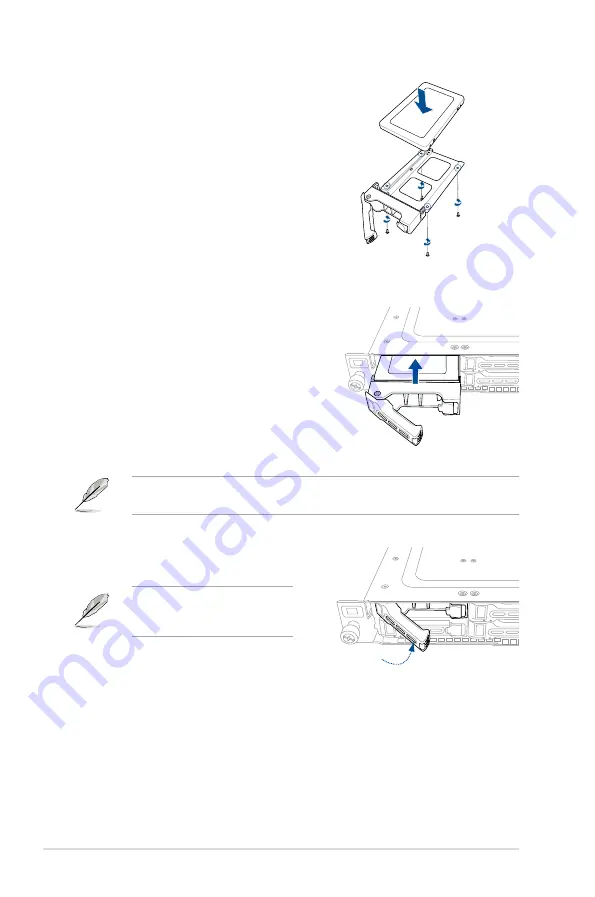
5.
Place the SATA/SAS/NVMe storage
device into the tray then secure it with
four screws.
6.
Insert the storage tray and storage
device assembly all the way into the
depth of the bay until just a small
fraction of the tray edge protrudes.
7.
Push the tray lever until it clicks and
secures the storage tray in place.
The storage tray is correctly placed
when its front edge aligns with the
bay edge.
8.
Repeat steps 1 to 7 to install the other
SATA/SAS/NVMe storage devices.
When installed, the SATA/SAS/NVMe connector on the storage device connects to the
SATA/SAS/NVMe interface on the backplane.
Содержание RS500A-E10 Series
Страница 1: ...1U Rackmount Server User Guide RS500A E10 Series RS500A E10 PS4 RS500A E10 RS4 RS500A E10 RS12U ...
Страница 10: ...x ...
Страница 64: ...Chapter 2 Hardware Information 2 38 ...
Страница 69: ...3 5 ASUS RS500A E10 Series 3 2 Rail kit dimensions 589mm 43 6mm 900mm 43 6mm ...
Страница 70: ...Chapter 3 Installation Options 3 6 ...
Страница 72: ...Chapter 4 Motherboard Information 4 2 4 1 Motherboard layout ...
Страница 92: ...Chapter 4 Motherboard Information 4 22 ...
Страница 139: ...Appendix Appendix ...
Страница 140: ...KRPA U16 block diagram RS500A E10 RS4 RS500A E10 PS4 ...
Страница 141: ...RS500A E10 RS12U ...


