background image

ASUS RS161-E5/PA2

4-11

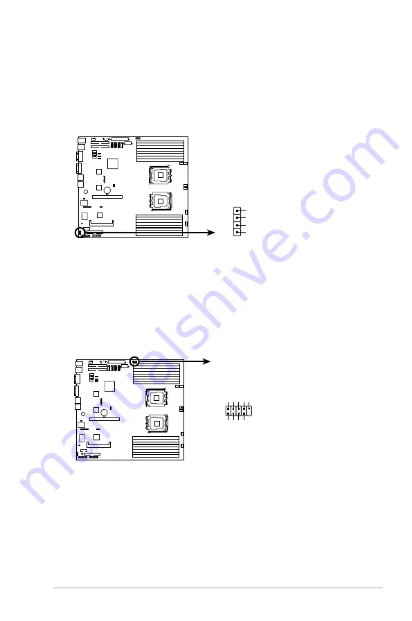
4.  Hard disk activity LED connector (4-pin HDLED1)

This connector is for the storage add-on card cable connected to the SCSI or 

SATA add-on card. The read or write activities of any device connected to the 

SCSI or SATA add-on card causes the front panel LED to light up.

KFSN4-DRE

®

KFSN4-DRE storage card activity LED connector

HDLED1

PIN1

ADD_IN_CARD-

NC

NC

ADD_IN_CARD-

5.  USB connector (10-1 pin USB34)

This connector is for USB 2.0 ports. Connect the USB module cable to 

this connector, then install the module to a slot opening at the back of the 

system chassis. This USB connector complies with USB 2.0 specification that 

supports up to 480 Mbps connection speed.

KFSN4-DRE

®

KFSN4-DRE USB connector

USB34

Power

PIN1

USB PortA(-) USB PortA(+

)

GND

Power

USB PortB(-) USB PortB(+

)

GND

NC

Содержание RS161-E5 - 0 MB RAM

Страница 1: ...RS161 E5 PA2 1U Rackmount Server Service Guide ...

Страница 2: ...on of business and the like even if ASUS has been advised of the possibility of such damages arising from any defect or error in this manual or product Specifications and information contained in this manual ae furnished for informational use only and are subject to change at any time without notice and should not be construed as a commitment by ASUS ASUS assumes no responsibility or liability for...

Страница 3: ... Unit CPU 2 4 2 2 1 Installing the CPU 2 4 2 2 2 Installing the CPU heatsink and airduct 2 6 2 3 System memory 2 8 2 3 1 Overview 2 8 2 3 2 Memory Configurations 2 9 2 3 3 Installing a DIMM 2 10 2 3 4 Removing a DIMM 2 10 2 4 Hard disk drives 2 11 2 5 Expansion slot 2 13 2 5 1 Installing an expansion card to the riser card bracket 2 13 2 5 2 Reinstalling the riser card bracket 2 14 2 5 3 Configuri...

Страница 4: ...lity 5 3 5 1 3 ASUS CrashFree BIOS 2 utility 5 5 5 2 BIOS setup program 5 6 5 2 1 BIOS menu screen 5 7 5 2 2 Menu bar 5 7 5 2 3 Navigation keys 5 7 5 2 4 Menu items 5 8 5 2 5 Sub menu items 5 8 5 2 6 Configuration fields 5 8 5 2 7 Pop up window 5 8 5 2 8 Scroll bar 5 8 5 2 9 General help 5 8 5 3 Main menu 5 9 5 3 1 System Date Day xx xx xxxx 5 9 5 3 2 System Time xx xx xx 5 9 5 3 3 Floppy A Disabl...

Страница 5: ...utility 6 2 6 2 NVIDIA RAID configurations 6 3 6 2 1 Setting the BIOS RAID items 6 3 6 2 2 Entering the NVIDIA RAID Utility 6 4 6 2 3 Creating a RAID Volume 6 5 6 2 4 Rebuilding a RAID set 6 7 6 2 5 Deleting a RAID array 6 8 6 2 6 Clearing the disk data 6 9 Chapter 7 Driver installation 7 1 RAID driver installation 7 2 7 1 1 Creating a RAID driver disk 7 2 7 1 2 Installing the RAID controller driv...

Страница 6: ... is encouraged to try to correct the interference by one or more of the following measures Reorient or relocate the receiving antenna Increase the separation between the equipment and receiver Connect the equipment to an outlet on a circuit different from that to which the receiver is connected Consult the dealer or an experienced radio TV technician for help Canadian Department of Communications ...

Страница 7: ...erver carefully read all the manuals included with the server package Before using the server make sure all cables are correctly connected and the power cables are not damaged If any damage is detected contact your dealer as soon as possible To avoid short circuits keep paper clips screws and staples away from connectors slots sockets and circuitry Avoid dust humidity and temperature extremes Plac...

Страница 8: ...s This chapter describes how to prepare the barebone server for rack mounting 4 Chapter 4 Motherboard information This chapter gives information about the motherboard that comes with the server This chapter includes the motherboard layout jumper settings and connector locations 5 Chapter 5 BIOS setup This chapter tells how to change the system settings through the BIOS Setup menus Detailed descrip...

Страница 9: ... to complete a task CAUTION Information to prevent damage to the components when trying to complete a task IMPORTANT Instructions that you MUST follow to complete a task NOTE Tips and information to aid in completing a task Reference Visit the ASUS websites worldwide that provide updated information for all ASUS hardware and software products Refer to the ASUS contact information for details ...

Страница 10: ... ...

Страница 11: ...ASUS RS161 E5 PA2 1 This chapter describes the general features of the barebone server including sections on the front panel and rear panel specifications Chapter 1 Product introduction ...

Страница 12: ...ap SATA II HDD trays SATA2 backplane 2 x PSU fan 40mm x 28mm 4 x System fan 40mm x 28 mm 2 x Device fan 40mm x 28 mm 1 x Airdut Cables AC power cable Pre connected cables Pre connected device power cables Accessories Rackmount rail kit 2 x CPU heatsink RS161 E5 PA2 user guide RS161 E5 PA2 support CD includes ASWM CA Anti virus software CD Bag of screws ASUS System Web based Management If any of th...

Страница 13: ...ECC Memory Size 512 MB 1 GB 2 GB 4 GB Expansion Slots Total PCI PCI X PCI E Slots 2 Slot Type 1 PCI E x16 slot x8 link Full Heigh Half length 1 PCI E x16 slot x8 link 4 2 x 5 66 Additional Slot 1 1 SO DIMM socket for optional ASMB3 SOL SATA Controller nForce Professional 2200 2 SATA2 300MB s ports Support software RAID 0 1 Windows HDD Bays I internal A or S will be hot swappable 2 Hot Swap SATA2 H...

Страница 14: ... 1 anti virus software Management Solution Software ASWM2 0 Out of Band Remote Management Optional ASMB3 SOL Safety US Canada UL1950 CSA950 Europe TUV CE EN55022 compliance to EU Directive 89 366 EEC Europe TUV EMI US FCC CFR47 Part 15 Class A Europe CE EN55022 EN55024 Australia C TICK Dimension 670mm 444mm 43 6mm Net Weight Kg CPU DRAM HDD not included 11 25Kg Power Supply 500W Single Power Suppl...

Страница 15: ... PSU fans The middle part includes the I O shield with openings for the rear panel connectors on the motherboard 1 AC power plug 2 PS 2 mouse port 3 LAN port for ASMB3 iKVM 4 Serial port 5 Expansion slot 6 Rear location LED 7 LAN port1 8 LAN port2 9 VGA port 10 USB ports 11 PS 2 keyboard port 12 PSU fans The ports for the PS 2 keyboard PS 2 mouse USB VGA and Gigabit LAN do not appear on the rear p...

Страница 16: ...ling the air duct for instructions 1 5 Internal features The barebone server includes the basic components as shown 1 PSU fans 2 ASUS KFSN4 DRE motherboard 3 Power supply 4 System fans 40mm x 28mm x 4 5 Device fans 40mm x 28mm x 2 6 2 x PCI E Slot riser card 7 SATA II backplane 8 Hot swap HDD tray 1 port0 9 Hot swap HDD tray 2 Port1 10 Optical drive 1 1 2 3 4 5 5 6 7 8 9 10 ...

Страница 17: ...System power ON Location LED OFF ON Normal status Location switch is pressed Press the location switch again to turn off Message LED OFF Blinking System is normal no incoming event ASWM indicates a HW monitor event LAN1 2 LEDs OFF Blinking ON No LAN connection LAN is transmitting or receiving data LAN connection is present Storage Access LED OFF Blinking No activity Read write data into the HDD 1 ...

Страница 18: ...n 1 ACT LINK LED SPEED LED Status Description Status Description OFF No link OFF 10 Mbps connection GREEN Linked ORANGE 100 Mbps connection BLINKING Data activity GREEN 1 Gbps connection 1 6 2 Rear panel LEDs SPEED LED ACT LINK LED ...

Страница 19: ...ASUS RS161 E5 PA2 2 This chapter lists the hardware setup procedures that you have to perform when installing or removing system components Chapter 2 Hardware setup ...

Страница 20: ...screw on each front end of the top cover 3 Firmly hold the cover and slide it toward the rear panel for about half an inch until it is disengaged from the chassis 4 Lift the cover from the chassis 2 Loosen the two thumbscrews on the rear panel to release the top cover from the chassis Thumbscrews 1 2 inch distance ...

Страница 21: ...e rear and leaving a gap of about half an inch from the front panel 2 Make sure that the pegs inside the cover two on each side are aligned to the grooves on the chassis 3 Slide the cover toward the front until it snaps in place 4 Tighten the thumbscrews on the rear to secure the cover Grooves Peg inside Thumbscrews ...

Страница 22: ...se Authorization RMA requests only if the motherboard comes with the cap on the CPU socket Ensure to install identical CPUs to the system DO NOT mix Quad core and Dual core CPUs When you install varying stepping and speed CPUs to the system the faster CPU downgrades and runs the speed as the slower one The product warranty does not cover damage to the socket contacts resulting from incorrect CPU i...

Страница 23: ...ure that the gold triangle is on the bottom right corner of the socket The socket alignment keys should fit into the CPU notches Load plate A B 2 Press the load lever with your thumb A then move it to the left B until it is released from the retention tab Retention tab Load lever This side of the socket box should face you PnP cap A B To prevent damage to the socket pins do not remove the PnP cap ...

Страница 24: ...efully place the heatsink on top of the installed CPU and secure the heatsink to the motherboard with a Philips cross screwdriver The CPU fits in only one correct orientation DO NOT force the CPU into the socket to prevent bending the connectors on the socket and damaging the CPU 6 Close the load plate A then push the load lever B until it snaps into the retention tab A B ...

Страница 25: ...2 ASUS RS161 E5 PA2 2 Carefully lower the airduct until it fits in place To install the airduct 1 Position the airduct on top of the heatsink ...

Страница 26: ... DIMM_D4 2 3 System memory 2 3 1 Overview The motherboard comes with sixteen 16 Double Data Rate 2 DDR2 Dual Inline Memory Modules DIMM sockets A DDR2 module has the same physical dimensions as a DDR DIMM but has a 240 pin footprint compared to the 184 pin DDR DIMM DDR2 DIMMs are notched differently to prevent installation on a DDR DIMM socket The figure illustrates the location of the DDR2 DIMM s...

Страница 27: ... performance Single CPU DIMM_A1 DIMM_A2 DIMM_B1 DIMM_B2 DIMM_A3 DIMM_A4 DIMM_B3 DIMM_B4 Dual CPU DIMM_A1 DIMM_A2 DIMM_B1 DIMM_B2 DIMM_C1 DIMM_C2 DIMM_D1 DIMM_D2 DIMM_A3 DIMM_A4 DIMM_B3 DIMM_B4 DIMM_C3 DIMM_C4 DIMM_D3 DIMM_D4 Always install DIMMs with the same CAS latency For optimum compatibility it is recommended that you obtain memory modules from the same vendor A1 B1 A2 B2 A3 B3 A4 B4 CPU1 Sin...

Страница 28: ...taining clips snap back in place and the DIMM is properly seated 2 3 4 Removing a DIMM Follow these steps to remove a DIMM 1 Simultaneously press the retaining clips outward to unlock the DIMM 2 Remove the DIMM from the socket A DDR2 DIMM is keyed with a notch so that it fits in only one direction Do not force a DIMM into a socket to avoid damaging the DIMM The DDR2 DIMM sockets do not support DDR...

Страница 29: ...ane To install a hot swap SATA HDD 1 Release a drive tray by pushing the spring lock to the right then pulling the tray lever outward The drive tray ejects slightly after you pull out the lever 2 Firmly hold the tray lever and pull the drive tray out of the bay 3 Take note of the drive tray holes Each side has three holes to fit different types of hard disk drives Use two screws on each side to se...

Страница 30: ...he drive tray is correctly placed when its front edge aligns with the bay edge 7 Repeat steps 1 to 6 if you wish to install a second SATA drive When installed the SATA connector on the drive connects to the SATA interface on the backplane 8 Connect the bundled SATA cables to the connectors on the SATA backplane Refer to section 2 7 SATA backplane cabling for information on the SATA backplane cable...

Страница 31: ...ce the riser card bracket on a flat and stable surface then remove the screw from the PCI E x16 slot bay 3 Install a PCI E card to the bracket as shown then secure the card with a screw 1 Firmly hold the riser card bracket then pull it up to detach it from the PCI Express slot on the motherboard Your add on card should be compliant with the PCI Express specification requirement or it might cause t...

Страница 32: ...ard bracket should match these holes to ensure that the bracket is properly in place 2 Install the riser card bracket with the card into the PCI Express x16 slot on the motherboard Pegs on the riser card bracket 3 Press the riser card bracket until the golden connectors completely fit the slot and the bracket aligns with the rear panel 4 Connect the cable s to the card if applicable ...

Страница 33: ... card Standard interrupt assignments These IRQs are usually available for ISA or PCI devices IRQ Priority Standard function 0 1 System Timer 1 2 Keyboard Controller 2 Programmable Interrupt 3 11 Communications Port COM2 4 12 Communications Port COM1 5 13 Sound Card sometimes LPT2 6 14 Floppy Disk Controller 7 15 Printer Port LPT1 8 3 System CMOS Real Time Clock 9 4 ACPI Mode when used 10 5 IRQ Hol...

Страница 34: ...rom motherboard to optical drive 5 Device fan connector from motherboard FRNT_FAN2 6 to device fans 6 SATA connectors from motherboard SATA 1 2 to SATA backplane board 7 Panel connector from motherboard to front I O board 8 Auxiliary panel connector from motherboard to front I O board 9 USB connector from motherboard to front I O board 10 PSUSMB1 connector from power supply 11 System fan connector...

Страница 35: ...2 2 7 SATA backplane cabling Connects the SATAII cable from SATA1 on the MB Connects the SMBus cable from the MB Connect the SATAII HDDs Connects a 4 pin plug from power supply Connects the SATAII cable from SATA2 on the MB ...

Страница 36: ...w to remove the following components 1 System fans 2 Device fan 3 Power supply module 4 Optical drive 5 Motherboard 2 8 1 System fans The system comes with four units of 28 mm x 40 mm 15500 rpm fan with dummy case Refer to the illustration below for location of the system fans 28 mm x 40 mm fan with dummy case Incorrect installation of the system fan with dummy case may result to CPU overheating a...

Страница 37: ...install the system fan 1 Insert the fan to the fan cage The airflow directional arrow on the fan side should point towards the system rear panel 2 Connect the system fan cable to the fan connector on the motherboard refer to 2 6 Cable connections 2 Lift the fan then set aside 3 Repeat step 1 to 2 to uninstall the other system fans ...

Страница 38: ...ninstall the fan following the instructions in the previous section 2 Pull the dummy case to the direction of the arrow just enough to disengage its pegs from the system fan To reinstall the system fan with the dummy case 1 Insert the dummy case pegs to the system fan holes until it fits in place 2 Reinstall the system fan by following the instructions in the previous section 3 Replace the system ...

Страница 39: ...t the device fan cable to the fan connector on the motherboard 2 8 3 Device fan The system comes with two 28 mm 40 mm 15500 rpm device fans with dummy Refer to the illustration below for location of the device fans To uninstall the device fan 1 Disconnect the device fan cable from the connector on the motherboard 2 Lift the fan then set aside 28 mm 40 mm device fans 1 2 1 2 ...

Страница 40: ...ted to the motherboard and other system devices 2 Use a Phillips cross screwdriver to remove the screws that secure the front end of the power supply 4 Slide the power supply forward for about half an inch then carefully lift it out from the chassis 3 From the rear panel remove two screws that secure the power supply from the chassis ...

Страница 41: ...il the drive tray ejects 3 Pull out half of the drive tray to remove the tray bezel 1 Disconnect the power and signal cables connected to the rear of the optical drive 4 Pull the center of the bezel outward A then lift the sides B to remove 5 Replace the drive tray Do not apply too much force when removing the bezel Too much force may break the drive tray ...

Страница 42: ...f the drive Keep the screws for later use 7 Pull the metal bracket to the direction of the arrow until its pegs disengage from the drive holes 8 Lift the metal bracket then set aside 9 Push the drive inward then lift it out from the chassis 10 Remove the metal rail on the other side of the drive ...

Страница 43: ...instructions on removing these components 3 Use a Philips cross screwdriver to remove the screws that secure the motherboard to the base of the chassis Refer to the illustration below for the location of the motherboard screws 4 Carefully lift the motherboard out of the chassis as shown KFSN4 DRE To reinstall the optical drive follow the instructions in the previous chapter in a reverse order When...

Страница 44: ...the motherboard until the rear panel ports fit in place 3 Use a Phillips cross screwdriver to secure the motherboard with ten 10 screws in the holes as shown in the illustration in the previous section 4 Reconnect all the required cables to the motherboard See section 2 6 Cable connections for details 5 Reinstall all the devices that you have previously removed ...

Страница 45: ...ASUS RS161 E5 PA2 2 This chapter describes how to install the optional components and devices into the barebone server Chapter 3 Installation options ...

Страница 46: ...and bolt type screws 3 2 Rack rails assembly To assemble the rack rails 1 Determine the depth of the rack where you wish to install the system 2 Match one long and one short rail to your desired length and fix them together using four 4 pairs of nuts and bolts 3 Repeat step 2 to assemble the other rail pair Nuts Bolts Left pair Right pair Front ends Rear ends Nuts on outer side Bolts on inner side...

Страница 47: ...pace where you attached the rail 6 Remove the screws from the rear 1U space and align the rear end holes 7 Drive in two screws on the outer holes to secure the rear end 8 From the rack front find the corresponding 1U space for the second rail pair 9 Repeat steps 2 to 7 to attach the second rail pair When properly installed the rack rails appear as shown 3 Align the front end holes of a rack rail p...

Страница 48: ...oth sides and insert the rear panel side to the front end of the rack rail then carefully push the server all the way to the back until the front panel fits the front end of the rack and the rack screws on the server match the middle hole on the rack 2 Tighten the two rack screws to secure the server to the rack Rack screw ...

Страница 49: ...ASUS RS161 E5 PA2 Chapter 4 Motherboard info This chapter includes the motherboard layout and brief descriptions of the jumpers and internal connectors ...

Страница 50: ... DDR2 DIMM_B3 64 72 bit 240 pin module DDR2 DIMM_A3 64 72 bit 240 pin module DDR2 DIMM_B2 64 72 bit 240 pin module DDR2 DIMM_A2 64 72 bit 240 pin module DDR2 DIMM_B1 64 72 bit 240 pin module DDR2 DIMM_A1 64 72 bit 240 pin module DDR2 DIMM_C1 64 72 bit 240 pin module DDR2 DIMM_D1 64 72 bit 240 pin module DDR2 DIMM_C2 64 72 bit 240 pin module DDR2 DIMM_D2 64 72 bit 240 pin module DDR2 DIMM_C3 64 72 ...

Страница 51: ...connectors 7 pin SATA1 SATA2 SATA3 SATA4 4 9 4 Hard disk activity LED connector 4 pin HDLED1 4 10 5 USB connectors 10 1 pin USB34 4 10 6 Front and rear fan connectors 4 pin FRNT_FAN1 2 3 4 REAR_FAN1 2 3 4 5 6 4 11 7 Serial port connectors 10 1 pin COM2 4 11 8 ATX power connectors 24 pin ATXPWR1 8 pin ATX12V1 4 12 9 Power supply SMBus connector 5 pin PSUSMB1 4 12 10 LPC debug card connector 14 1 pi...

Страница 52: ... component The illustration below shows the location of the onboard LED KFSN4 DRE KFSN4 DRE Onboard LED ON OFF MEM_WARN1 Abnormal Normal green ON OFF CPU_WARN1 Abnormal Normal green 2 CPU warning LED CPU_WARN1 The CPU warning LED lights up to indicate that a processor is not installed or the processor is not installed properly in CPU 1 socket 3 Memory warning LED MEM_WARN1 The memory warning LED l...

Страница 53: ...ton cell battery powers the RAM data in CMOS which include system setup information such as system passwords To erase the RTC RAM 1 Turn OFF the computer and unplug the power cord 2 Remove the onboard battery 3 Move the jumper cap from pins 1 2 default to pins 2 3 Keep the cap on pins 2 3 for about 5 10 seconds then move the cap back to pins 1 2 4 Reinstall the battery 5 Plug the power cord and tu...

Страница 54: ... activate the Gigabit LAN feature KFSN4 DRE KFSN4 DRE LAN setting LAN1_EN1 Enable Default Disable LAN2_EN1 Enable Default Disable 2 3 1 2 2 3 1 2 3 VGA Graphics controller setting 3 pin VGA_EN1 This jumper allows you to enable or disable the onboard ATI ES1000 video graphics controller Set to pins 1 2 to enable the video graphics controller KFSN4 DRE KFSN4 DRE VGA setting VGA_EN1 Enable Default Di...

Страница 55: ...ans or pins 2 3 for 3 pin fans KFSN4 DRE KFSN4 DRE FAN setting FAN_SEL1 1 2 2 3 4 PIN FAN Default 3 PIN FAN If you use a 4 pin fan but set the jumper to pin 2 3 the fan you installed may not work If you use a 3 pin fan but set the jumper for a 4 pin fan the fan controll will not work and the fan you installed will always run at full speed ...

Страница 56: ... floppy disk that contains the latest BIOS for the motherboard and the Afudos utility Make sure you download the correct BIOS for your motherboard model 2 Set the jumper to pins 2 3 3 Insert the floppy disk then turn on the system to update the BIOS 4 Shut down the system 5 Set the jumper back to pins 1 2 6 Turn on the system KFSN4 DRE KFSN4 DRE BIOS recovery setting RECOVERY1 Disable Default Enab...

Страница 57: ...the signal connector at the back of the floppy disk drive KFSN4 DRE NOTE Orient the red markings on the floppy ribbon cable to PIN 1 PIN 1 FLOPPY1 KFSN4 DRE Floppy disk drive connector 2 IDE connectors 40 1 pin PRI_IDE1 SEC_IDE1 The onboard IDE connectors are for Ultra DMA 133 100 66 signal cables KFSN4 DRE KFSN4 DRE IDE connector NOTE Orient the red markings usually zigzag on the IDE ribbon cable...

Страница 58: ...If you installed Serial ATA hard disk drives you can create a RAID 0 RAID 1 RAID 1 0 RAID 5 or JBOD configuration The actual data transfer rate depends on the speed of Serial ATA hard disks installed KFSN4 DRE SATA2 KFSN4 DRE SATA connectors GND RSATA_TXP2 RSATA_TXN2 GND RSATA_RXN2 RSATA_RXP2 GND SATA1 GND RSATA_TXP1 RSATA_TXN1 GND RSATA_RXN1 RSATA_RXP1 GND SATA4 GND RSATA_TXP4 RSATA_TXN4 GND RSAT...

Страница 59: ...N4 DRE KFSN4 DRE storage card activity LED connector HDLED1 PIN1 ADD_IN_CARD NC NC ADD_IN_CARD 5 USB connector 10 1 pin USB34 This connector is for USB 2 0 ports Connect the USB module cable to this connector then install the module to a slot opening at the back of the system chassis This USB connector complies with USB 2 0 specification that supports up to 480 Mbps connection speed KFSN4 DRE KFSN...

Страница 60: ...art Fan technology KFSN4 DRE KFSN4 DRE Fan connectors FRNT_FAN1 FRNT_FAN6 FRNT_FAN5 REAR_FAN4 REAR_FAN3 REAR_FAN2 REAR_FAN1 GND FAN Power FAN Speed PWM Control FRNT_FAN4 FRNT_FAN3 FRNT_FAN1 FRNT_FAN2 GND FAN Power FAN Speed PWM Control REAR_FAN4 GND FAN Power FAN Speed PWM Control REAR_FAN3 GND FAN Power FAN Speed PWM Control REAR_FAN2 GND FAN Power FAN Speed PWM Control REAR_FAN1 FRNT_FAN2 GND FA...

Страница 61: ... power output is recommended when configuring a system with more power consuming devices The system may become unstable or may not boot up if the power is inadequate Make sure that your power supply unit PSU can provide at least the minimum power required by your system See the table below for details KFSN4 DRE KFSN4 DRE ATX power connectors 8 pin GND 12V2 GND 12V2 GND 12V1 GND 12V1 24 pin Power C...

Страница 62: ...LAD1 PLTRST LFRAME_N CLK GND KFSN4 DRE LPC debug card connector J1 9 Power Supply SMBus connector 5 pin PSUSMB1 This connector allows you to connect SMBus System Management Bus to the power supply unit to read PSU information Devices communicate with an SMBus host and or other SMBus devices using the SMBus interface KFSN4 DRE KFSN4 DRE Power supply SMBus connector PSUSMB1 3 3V Remote Sense GND NC ...

Страница 63: ...rusion connector 3 pin CASEOPEN This lead is for a chassis with an intrusion detection feature This requires an external detection mechanism such as a chassis intrusion sensor or microswitch When you remove any chassis component the sensor triggers and sends a high level signal to this lead to record a chassis intrusion event 5 Locator LED 1 2 pin LOCATORLED1 This 2 pin connector is for the Locato...

Страница 64: ...s and warnings 4 Hard disk drive activity LED Red 2 pin IDE_LED This 2 pin connector is for the HDD Activity LED Connect the HDD Activity LED cable to this connector The IDE LED lights up or flashes when data is read from or written to the HDD 5 ATX power button soft off button Green 2 pin PWRSW This connector is for the system power button Pressing the power button turns the system on or puts the...

Страница 65: ...ASUS RS161 E5 PA2 5 Chapter 5 BIOS setup This chapter tells how to change the system settings through the BIOS Setup menus Detailed descriptions of the BIOS parameters are also provided ...

Страница 66: ...estore the BIOS in the future Copy the original motherboard BIOS using the ASUS Update or AFUDOS utilities 5 1 1 Creating a bootable floppy disk 1 Do either one of the following to create a bootable floppy disk DOS environment a Insert a 1 44MB floppy disk into the drive b At the DOS prompt type format A S then press Enter Windows XP environment a Insert a 1 44 MB floppy disk to the floppy disk dr...

Страница 67: ...ight alphanumeric characters for the main filename and three alphanumeric characters for the extension name A afudos oOLDBIOS1 rom Make sure that the floppy disk is not write protected and has at least 1024KB free space to save the file The succeeding BIOS screens are for reference only The actual BIOS screen displays may not be same as shown The utility returns to the DOS prompt after copying the...

Страница 68: ...RE ROM AMI Firmware Update Utility Version 1 19 ASUS V2 07 03 11 24BB Copyright C 2002 American Megatrends Inc All rights reserved WARNING Do not turn off power during flash BIOS Reading file done Reading flash done Advance Check Erasing flash done Writing flash done Verifying flash done Please restart your computer A A afudos iKFSN4DRE ROM AMI Firmware Update Utility Version 1 19 ASUS V2 07 03 11...

Страница 69: ...wing message and automatically checks the floppy disk for the original or updated BIOS file Bad BIOS checksum Starting BIOS recovery Checking for floppy 4 Restart the system after the utility completes the updating process Bad BIOS checksum Starting BIOS recovery Checking for floppy Floppy found Reading file KFN4DRE ROM Completed Start flashing DO NOT shut down or reset the system while updating t...

Страница 70: ...s program Press Del during the Power On Self Test POST to enter the Setup utility otherwise POST continues with its test routines If you wish to enter Setup after POST restart the system by pressing Ctrl Alt Delete or by pressing the reset button on the system chassis You can also restart by turning the system off and then back on Do this last option only if the first two failed The Setup program ...

Страница 71: ...loading default settings To select an item on the menu bar press the right or left arrow key on the keyboard until the desired item is highlighted 5 2 3 Navigation keys At the bottom right corner of a menu screen are the navigation keys for that particular menu Use the navigation keys to select items in the menu and change the settings 5 2 1 BIOS menu screen Some of the navigation keys differ from...

Страница 72: ...ss Enter to display a list of options Refer to 5 2 7 Pop up window 5 2 7 Pop up window Select a menu item then press Enter to display a pop up window with the configuration options for that item 5 2 8 Scroll bar A scroll bar appears on the right side of a menu screen when there are items that do not fit on the screen Press the Up Down arrow keys or Page Up Page Down keys to display the other items...

Страница 73: ...n the menu screen items and how to navigate through them V02 61 C Copyright 1985 2006 American Megatrends Inc BIOS SETUP UTILITY Main Advanced Server Security Boot Exit Use ENTER to select a field Use or to configure system Date System Date Wed 07 25 2007 System Time 11 07 30 Floppy A Disabled IDE Configuration Primary IDE Master Not Detected Primary IDE Slave Not Detected Secondary IDE Master Not...

Страница 74: ...tion options Disabled Primary Secondary Both IDE DMA Transfer Enabled Enables or disables the BIOS to use PCI busmastering for reading writing to IDE drives Configuration options Disabled Enabled nVidia RAID Setup DISABLED disables the integrated IDE Controller PRIMARY enables only the Primary IDE Controller SECONDARY enables only the Secondary IDE Controller BOTH enables both IDE Controllers BIOS...

Страница 75: ... enables the LBA mode if the device supports this mode and if the device was not previously formatted with LBA mode disabled Configuration options Disabled Auto Block Multi sector Transfer Auto Enables or disables data multi sectors transfers When set to Auto the data transfer from and to the device occurs multiple sectors at a time if the device supports multi sector transfer feature When set to ...

Страница 76: ...Disabled Enables or disables 32 bit data transfer Configuration options Disabled Enabled 5 3 6 System Information This menu gives you an overview of the general system specifications The BIOS automatically detects the items in this menu V02 61 C Copyright 1985 2006 American Megatrends Inc BIOS SETUP UTILITY Main System Information Model Name ASUS KFSN4 DRE RS161 Model ID 8067A0 ASUS BIOS Version 1...

Страница 77: ...it ESC Exit Processor Displays the installed processor information System Memory Displays the installed system memory information BIOS SETUP UTILITY Main System Memory Information Total Memory 2048MB Node1 Memory Configuration Node2 Memory Configuration Node1 2 Memory Configuration V02 61 C Copyright 1985 2006 American Megatrends Inc BIOS SETUP UTILITY Main Speed DDR2 400 DIMM_A1 512MB DIMM_B1 Non...

Страница 78: ...SB Configuration Peripheral Devices Configuration ACPI Configuration APM Configuration Hardware Monitor Select Screen Select Item Change Field Tab Select Field F1 General Help F10 Save and Exit ESC Exit V02 61 C Copyright 1985 2006 American Megatrends Inc BIOS SETUP UTILITY Advanced CPU Configuration MPS Table Version 1 4 MTRR Mapping Continuous PowerNow Enabled Secure Virtual Machine Mode Enabled...

Страница 79: ...Trrd 2 CLK Row Cycle Trc 12 CLK NUMA Function Enabled Select Screen Select Item Change Field Tab Select Field F1 General Help F10 Save and Exit ESC Exit MTRR Mapping Continuous Determines the method used for programming processor MTRRs when using more than 4GB of system memory Configuration options Continuous Discrete PowerNow Enabled Enables or disables the generation of ACPI_PPC _PSS _PCT object...

Страница 80: ... memory interleaving Configuration options Disabled Auto Node Interleaving Disabled Enables node interleaving Configuration options Disabled Enabled Channel Interleaving Auto Enables channel memory interleaving Configuration options Disabled Auto Reserved Reserved Reserved Memory Hole Remapping Enabled Enables memory remapping around memory hole Configuration options Disabled Enabled Unganged Mode...

Страница 81: ...tems appear when DRAM Timing Mode is set to DCT 0 DCT 1 or Both We strongly recommend you not to change the default value of the following items Changing the values might cause the system unstable CAS Latency CL Auto Configuration options Auto 3 CLK 4 CLK 5 CLK 6 CLK TRCD Auto Configuration options 3 CLK 4 CLK 5 CLK 6 CLK Auto TRP Auto Configuration options 3 CLK 4 CLK 5 CLK 6 CLK Auto tRTP Auto C...

Страница 82: ...isabled tRWTTO 2 CLK Configuration options 2 CLK 3 CLK 4 CLK 5 CLK 6 CLK 7 CLK 8 CLK 9 CLK Auto tWRRD 0 CLK Configuration options 0 CLK 1 CLK 2 CLK 3 CLK Auto tWTR Auto Configuration options Auto 1 CLK 2 CLK 3 CLK tWRWR 1 CLK Configuration options 1 CLK 2 CLK 3 CLK 4 CLK Auto tRDRD 2 CLK Configuration options 2 CLK 3 CLK 4 CLK 5 CLK Auto tRFC0 Auto Configuration options 75ns 105ns 127 5ns 195ns 32...

Страница 83: ...te option to ensure proper AGP operation Configuration options AGP Present Disabled 32MB 64MB 128MB 256MB 512MB 1GB NUMA Function Enabled Enables or disables the building of ACPI SRAT Table Configuration options Enabled Disabled DRAM ECC Enable Enabled Configuration options Enabled Disabled DRAM SCRUB REDIRECT Enabled Configuration options Enabled Disabled 4 Bit ECC Mode Enabled Configuration opti...

Страница 84: ...hange Field Tab Select Field F1 General Help F10 Save and Exit ESC Exit SouthBridge CK804 Configuration The SouthBridge CK804 Configuration menu allows you to change the Southbridge settings CPU Spread Spectrum Center Spread Sets or disables the processor clock spread spectrum Configuration options Disabled Center Spread Down Spread CPU Spread Spectrum Center Spread ...

Страница 85: ... Incorrect field values can cause the system to malfunction Reset ESCD Data No Clears the non volatile RAM NVRAM during boot Configuration options No Yes Plug And Play O S No When set to No BIOS configures all the devices in the system When set to Yes and if you install a Plug and Play operating system the operating system configures the Plug and Play devices not required for boot Configuration op...

Страница 86: ... If detected the USB controller legacy mode is enabled If no USB device is detected the legacy USB support is disabled Configuration options Disabled Enabled Auto The following items appear when you set Legacy SUB Support to Enabled or Auto USB 2 0 Controller Mode HiSpeed Allows you to set the USB 2 0 controller mode to HiSpeed 480 Mbps or FullSpeed 12 Mbps Configuration options FullSpeed HiSpeed ...

Страница 87: ...ral Devices Configuration OnBoard Floppy Controller Enabled Enables or disables the onboard floppy controller Configuration options Disabled Enabled Serial Port1 Address 3F8 IRQ4 Allows you to select the Serial Port1 base address Configuration options Disabled 3F8 IRQ4 3E8 IRQ4 2E8 IRQ3 Serial Port2 Address 2F8 IRQ3 Allows you to select the Serial Port2 base address Configuration options Disabled ...

Страница 88: ...it 5 4 6 ACPI Configuration ACPI Version Features ACPI v2 0 Configuration options ACPI v1 0 ACPI v2 0 ACPI v3 0 Headless Mode Disabled Enables or disables the headless operation mode in ACPI Configuration options Disabled Enabled ACPI EMS Support Disabled Enables or disables the ACPI EMS support Configuration options Disabled Enabled ACPI MCFG Support Enabled Enables or disables the ACPI MCFG supp...

Страница 89: ...an AC power loss When set to Last State the system goes into either off or on state whatever the system state was before the AC power loss Configuration options Power Off Power On Last State Resume By Ring Disabled When set to Enabled the system will generate a wake event when the external modem receives a call while the computer is in Soft off mode Configuration options Disabled Enabled Resume By...

Страница 90: ...therboard and CPU temperatures Select Ignored if you do not wish to display the detected temperatures The CPU2 Temperature shows N A if no processor is installed in CPU2 socket Front1 2 3 4 5 6 Fan Speed xxxxRPM or N A Rear1 2 3 4 Fan Speed xxxxRPM or N A The onboard hardware monitor automatically detects and displays the front and rear fan speed in rotations per minute RPM If the fan is not conne...

Страница 91: ...5 80 85 System1 Target Temperature 70 Allows you to set the system target temperature Configuration options 40 45 50 55 60 65 70 75 80 85 VCORE1 Voltage VCORE2 Voltage 3V Voltage 5V Voltage 5VSB Voltage VBAT Voltage 12V Voltage VTT VSEN1 2 The onboard hardware monitor automatically detects the voltage output through the onboard voltage regulators The VCORE2 item shows N A if no processor is instal...

Страница 92: ... set to Enabled 5 5 Server menu V02 61 C Copyright 1985 2006 American Megatrends Inc BIOS SETUP UTILITY Main Advanced Server Security Boot Exit Remote Access Configuration Select Screen Select Item Change Field Tab Select Field F1 General Help F10 Save and Exit ESC Exit V02 61 C Copyright 1985 2006 American Megatrends Inc BIOS SETUP UTILITY Server Configure Remote Access type and parameters Remote...

Страница 93: ...OS POST Always Sets the redirection mode after the BIOS Power On Self Test POST Some operating system may not work when set to Always Configuration options Disabled Boot Loader Always Terminal Type ANSI Allows you to select the target terminal type Configuration options ANSI VT100 VT UTF8 VT UTF8 Combo Key Support Disabled Enables or disables the VT UTF8 combo key support for ANSI or VT100 termina...

Страница 94: ...you successfully set your password To change the supervisor password follow the same steps as in setting a user password To clear the supervisor password select the Change Supervisor Password then press Enter The message Password Uninstalled appears If you forget your BIOS password you can clear it by erasing the CMOS Real Time Clock RTC RAM See section 2 6 Jumper for information on how to erase t...

Страница 95: ...ser Password item and press Enter 2 On the password box that appears type a password composed of at least six letters and or numbers then press Enter 3 Confirm the password when prompted The message Password Installed appears after you set your password successfully To change the user password follow the same steps as in setting a user password Password Check Setup When set to Setup BIOS checks fo...

Страница 96: ...egatrends Inc BIOS SETUP UTILITY Main Advanced Server Security Boot Exit Boot Device Priority Boot Settings Configuration Select Screen Select Item Change Field Tab Select Field F1 General Help F10 Save and Exit ESC Exit V02 61 C Copyright 1985 2006 American Megatrends Inc BIOS SETUP UTILITY Boot Boot Device Priority 1st Boot Device 1st FLOPPY DRIVE 2nd Boot Device Network MBA v8 3 9 3rd Boot Devi...

Страница 97: ...Enabled Auto POST Error Enabled When set to Enabled the system waits for the F1 key to be pressed when error occurs Configuration options Disabled Enabled Setup Prompt Enabled When set to Enabled the system displays the message Press DEL to run Setup during POST Configuration options Disabled Enabled Interrupt 19 Capture Enabled When set to Enabled this function allows the option ROMs to trap Inte...

Страница 98: ...e PC is turned off When you select this option a confirmation window appears Select YES to save changes and exit If you attempt to exit the Setup program without saving your changes the program prompts you with a message asking if you want to save your changes before exiting Press Enter to save the changes while exiting Exit Discard Changes Select this option only if you do not want to save the ch...

Страница 99: ...ASUS RS161 E5 PA2 2 This chapter provides instructions for setting up creating and configuring RAID sets using the available utilities Chapter 6 RAID Configuration ...

Страница 100: ...for this setup The new drive must be of the same size or larger than the existing drive If you want to boot the system from a hard disk drive included in a created RAID set copy first the RAID driver from the support CD to a floppy disk before you install an operating system to the selected hard disk drive Refer to Chapter 7 for details 6 1 2 Installing hard disk drives The motherboard supports Se...

Страница 101: ...items in the BIOS before setting your RAID configuration To set the BIOS RAID items 1 Enter the BIOS Setup during POST 2 Go to the Main Menu select IDE Configuration then press Enter 3 Set the RAID Option ROM item to Enabled then press Enter The master and slave drive list appears 4 Enable the drives you want to set as RAID 5 Save your changes then exit the BIOS Setup Refer to Chapter 5 for detail...

Страница 102: ...ed to specify Master or Slave is obsolete At the bottom section of the screen are the navigation keys These keys allow you to move through and select menu options ESC QUIT F6 Back F7 Finish TAB Navigate Select ENTER Popup The navigation keys vary depending on the menu level or option ESC QUIT F6 Back F7 Finish TAB Navigate Select ENTER Popup RAID Mode Striping Striping Block Optimal Free Disks Arr...

Страница 103: ...ing Stripe Mirroring Spanning RAID 5 2 Press TAB to select the Striping Block option then press Enter The following submenu appears The available stripe size values range from 4KB to 128KB The default stripe size is optimal 64KB You must choose the stripe size value based on the projected drive usage For low disk usage select 4 KB 16 KB For typical disk usage select 64 KB Select 128KB for performa...

Страница 104: ...a 6 The utility displays the created RAID set Press Ctrl X to save your settings and exit the utility ESC QUIT F6 Back F7 Finish TAB Navigate Select ENTER Popup RAID Mode Striping Striping Block Optimal Free Disks Array Disks Loc Disk Model Name Loc Disk Model Name 1 0 M XXXXXXXXXXXXXXXXXX Add 1 1 M XXXXXXXXXXXXXXXXXX Del NVIDIA RAID Utility Mar 23 2006 Define a New Array Ctrl X Exit Select B Set ...

Страница 105: ...rray or Esc to cancel The Array List screen displays the RAID set after rebuilding Select F6 Back F7 Finish Array 1 NVIDIA MIRROR XXX XXG Array Detail RAID Mode Striping Striping Width 1 Striping Block 64K Adapt Channel M S Index Disk Model Name Capacity 2 1 Master 0 XXXXXXXXXXXXXXXXX XXX XXGB 1 0 Master 1 XXXXXXXXXXXXXXXXX XXX XXGB Ctrl X Exit Select B Set Boot N New Array ENTER Detail NVIDIA RAI...

Страница 106: ...on message appears 3 Press Y to delete the array or press N to cancel 4 The Define a New Array menu appears when you press Y Create a new RAID set following the instructions in the previous sections You will lose all data on the drives if you delete a disk array Delete this array Y Yes N Cancel R Rebuild D Delete C Clear Disk ENTER Return NVIDIA RAID Utility Mar 23 2006 Array List Boot Id Status V...

Страница 107: ...Return Array 1 NVIDIA MIRROR XXX XXG Array Detail RAID Mode Striping Striping Width 1 Striping Block 64K Adapt Channel M S Index Disk Model Name Capacity 2 1 Master 0 XXXXXXXXXXXXXXXXX XXX XXGB 1 0 Master 1 XXXXXXXXXXXXXXXXX XXX XXGB 3 Press Y to clear the disk data or press N to cancel Press C to clear disk The following confirmation message appears Ctrl X Exit Select B Set Boot N New Array ENTER...

Страница 108: ...Chapter 6 RAID Configuration 6 10 ...

Страница 109: ...ASUS RS161 E5 PA2 Chapter 7 Driver installation This chapter provides instructions for installing the necessary drivers for different system components ...

Страница 110: ...ded in a RAID set You can create a RAID driver disk in DOS using the Makedisk application in the support CD or in Windows environment To create a RAID driver disk in DOS environment 1 Place the motherboard support CD in the optical drive 2 Restart the computer then enter the BIOS Setup 3 Select the optical drive as the first boot priority to boot from the support CD Save your changes then exit the...

Страница 111: ... RAID driver and place a blank high density floppy disk to the floppy disk drive 8 Press Enter 9 Follow screen instructions to create the driver disk nVIDIA nForce CK804 RAID Driver Windows 2000 Server Windows Server 2003 32 bit Windows Server 2003 64 bit Back Exit ...

Страница 112: ...AID Driver to create an nVIDIA nForce SATA RAID driver disk To install the RAID driver 1 Install an operating system to the selected hard disk drive During installation the computer prompts you to press the F6 if you are installing a third party SCSI or RAID driver 2 Press F6 then insert the RAID driver disk to the floppy disk drive 3 Follow screen instructions to install the RAID drivers ...

Страница 113: ...en installing Windows 2000 2003 Server OS 1 Boot the computer using the Windows 2000 2003 Server installation CD The Windows 2000 2003 Setup starts 2 Press F6 when the message Press F6 if you need to install a third party SCSI or RAID driver appears at the bottom of the screen 3 When prompted press S to specify an additional device ...

Страница 114: ...river disk you created earlier to the floppy disk drive then press Enter 5 Select the NVIDIA RAID CLASS DRIVER required then press Enter 6 Press S again and select NVIDIA nForce Storage Controller required at the Specigy Devices screen then press Enter ...

Страница 115: ...IVER required then press Enter The following windows appears listing both drrvers 8 Press Enter to continuen with Windows 2000 2003 installation DO NOT remove the floppy disk until the blue screen portion of Windows 2000 2003 installation is completed ...

Страница 116: ... the motherboard system support CD to the optical drive The CD automatically displays the Drivers menu if Autorun is enabled in your computer Windows automatically detects the LAN controllers and displays a New Hardware Found window Click Cancel to close this window If Autorun is NOT enabled in your computer browse the contents of the support CD to locate the file ASSETUP EXE from the BIN folder D...

Страница 117: ...ASUS RS161 E5 PA2 7 4 Click Next when the InstallShield Wizard window appears 5 Toggle I accept the terms in the license agreement and click Next to continue ...

Страница 118: ...7 10 Chapter 7 Driver installation 6 Click Install to start the installation 7 Click Finish to exit the wizard when the installation is completed ...

Страница 119: ... nVIDIA drivers on a Windows 2000 Server 2003 OS 1 Restart the computer and then log on with Administrator privileges 2 Insert the motherboard system support CD to the optical drive The CD automatically displays the Drivers menu if Autorun is enabled in your computer If Autorun is NOT enabled in your computer browse the contents of the support CD to locate the file ASSETUP EXE from the BIN folder ...

Страница 120: ...7 12 Chapter 7 Driver installation 4 Click Next when the InstallShield Wizard window appears 5 Check the box before the driver you want to install and click Next to continue ...

Страница 121: ...ASUS RS161 E5 PA2 7 13 6 Click Next to start the installation 7 Click Finish to exit the wizard when the installation is completed ...

Страница 122: ...es 7 4 1 Running the support CD Place the support CD to the optical drive The CD automatically displays the Drivers menu if Autorun is enabled in your computer If Autorun is NOT enabled in your computer browse the contents of the support CD to locate the file ASSETUP EXE from the BIN folder Double click the ASSETUP EXE to run the CD 7 4 2 Drivers menu The Drivers menu shows the available device dr...

Страница 123: ...ations Click an item to install 7 4 4 Utilities menu The Utilities menu displays the software applications and utilities that the motherboard supports Click an item to install 7 4 5 Contact information Click the Contact tab to display the ASUS contact information You can also find this information on the inside front cover of this user guide ...

Страница 124: ...7 16 Chapter 7 Driver installation ...

Отзывы: