1-8
Chapter 1: Product Introduction
Chapter 1
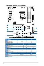
Recommended VGA configuration
Slot Description
Single VGA
Dual VGA
Triple VGA
2.
PCIe 3.0 x16_1
x16
x8
x8
4.
PCIe 3.0 x16_2
-
x8
x8
6.
PCIe 3.0 x16_3
-
-
x4
•
We recommend that you provide sufficient power when running CrossFireX™ or SLI
®
mode.
•
Ensure to connect the 8-pin and 4-pin power plugs when running CrossFireX™ or
SLI
®
mode.
•
Connect a chassis fan to the chassis fan connectors when using multiple graphics
cards for better thermal environment.
PCIEX16_3 shares bandwidth with M.2_2. PCIEX16_3 will be disabled when M.2_2 runs
x4 mode, and PCIEX16_3 will run x1 mode when M.2_2 runs x2 mode.
Slot Description
Up to 2 Intel
®
SSD on CPU
support
Up to 3 Intel
®
SSD on CPU
support
2.
PCIe 3.0 x16_1
-
x8+x4+x4
4.
PCIe 3.0 x16_2
x4+x4
-
•
Hyper M.2 X16 series card sold separately.
•
When using up to 2 Intel
®
SSD on CPU support, PCIe 3.0 x16_1 will run at x8.
•
When using up to 3 intel
®
SSD on CPU support, PCIe 3.0 x16_2 will be disabled. If
you wish to connect a display, we suggest using the internal VGA, or installing a VGA
card to PCIe x16_3, which will run at x4.
•
Enable the Hyper M.2 X16 series card under BIOS settings.
Hyper M.2 X16 series card configuration
Содержание ROG MAXIMUS XII HERO WI-FI
Страница 1: ...Motherboard ROG MAXIMUS XII HERO WI FI ...
Страница 4: ...iv Appendix Q Code table A 1 Notices A 5 ASUS contact information A 12 ...
Страница 16: ...xvi ...
Страница 18: ...1 2 Chapter 1 Product Introduction Chapter 1 1 2 Motherboard layout ...
Страница 44: ...2 2 Chapter 2 Basic Installation Chapter 2 ...
Страница 47: ...ROG MAXIMUS XII HERO WI FI 2 5 Chapter 2 2 1 3 DIMM installation To remove a DIMM ...
Страница 53: ...ROG MAXIMUS XII HERO WI FI 2 11 Chapter 2 2 1 8 SATA device connection OR ...
Страница 64: ...2 22 Chapter 2 Basic Installation Chapter 2 ...
Страница 70: ...3 6 Chapter 3 BIOS Setup Chapter 3 ...


