background image

4-14

Chapter 4: Software support

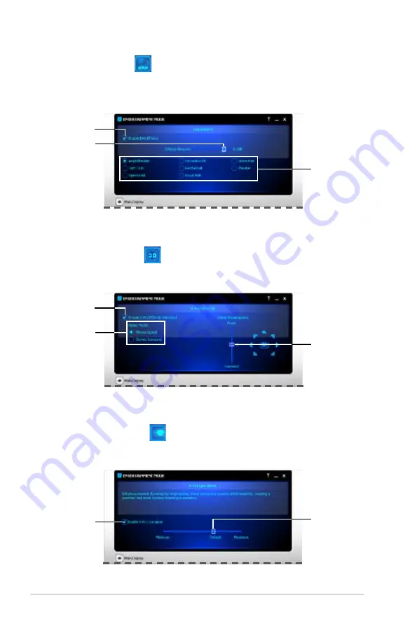
EAX Effects Panel 

This panel contains environment effects that you can select to obtain a sense of 

realism during interactive 3D games.

Click to enable 

EAX Effects

X-Fi CMSS-3D Panel 

This panel allows you to configure 3D virtual surround effects.

Click to select 

an environment

Drag to adjust 

effects amount

Click to enable 

X-Fi 3D Virtual 

effects

Drag to adjust 

effects

Click to select 

an upmix mode 

(appears when 

using 4/4.1/5.1/7.1 

Speakers)

X-Fi Crystalizer Panel 

Enable X-Fi Crystalizer to obtain more audio dynamics.

Click to enable 

X-Fi Crystalizer

Drag to adjust 

effects

Содержание Rampage Extreme - Motherboard - ATX

Страница 1: ...Motherboard Rampage Extreme ...

Страница 2: ...RCHANTABILITY OR FITNESS FOR A PARTICULAR PURPOSE IN NO EVENT SHALL ASUS ITS DIRECTORS OFFICERS EMPLOYEES OR AGENTS BE LIABLE FOR ANY INDIRECT SPECIAL INCIDENTAL OR CONSEQUENTIAL DAMAGES INCLUDING DAMAGES FOR LOSS OF PROFITS LOSS OF BUSINESS LOSS OF USE OR DATA INTERRUPTION OF BUSINESS AND THE LIKE EVEN IF ASUS HAS BEEN ADVISED OF THE POSSIBILITY OF SUCH DAMAGES ARISING FROM ANY DEFECT OR ERROR IN...

Страница 3: ...oceed 2 1 2 2 Motherboard overview 2 4 2 2 1 Motherboard layout 2 4 2 2 2 SupremeFX X Fi audio card layout 2 4 2 2 3 Layout contents 2 5 2 2 4 Placement direction 2 6 2 2 5 Screw holes 2 6 2 3 Central Processing Unit CPU 2 7 2 3 1 Installing the CPU 2 8 2 3 2 Installing the CPU heatsink and fan 2 11 2 3 3 Uninstalling the CPU heatsink and fan 2 12 2 4 System memory 2 13 2 4 1 Overview 2 13 2 4 2 M...

Страница 4: ...y 2 42 2 8 5 Replacing NB or MOS Thermal Kit 2 44 2 8 6 Installing DIY Pedestal 2 46 2 9 Starting up for the first time 2 47 2 10 Turning off the computer 2 48 2 10 1 Using the OS shut down function 2 48 2 10 2 Using the dual function power switch 2 48 Chapter 3 BIOS setup 3 1 Managing and updating your BIOS 3 1 3 1 1 ASUS Update utility 3 1 3 1 2 ASUS EZ Flash 2 utility 3 4 3 1 3 AFUDOS utility 3...

Страница 5: ...5 2 Onboard Devices Configuration 3 27 3 5 3 USB Configuration 3 29 3 5 4 PCI PnP 3 30 3 5 5 LCD Poster and LED Control 3 30 3 5 6 Other Configuration 3 32 3 6 Power menu 3 33 3 6 1 Suspend Mode 3 33 3 6 2 Repost Video on S3 Resume 3 33 3 6 3 ACPI 2 0 Support 3 33 3 6 4 ACPI APIC Support 3 33 3 6 5 APM Configuration 3 34 3 6 6 Hardware Monitor 3 35 3 7 Boot menu 3 38 3 7 1 Boot Device Priority 3 3...

Страница 6: ...go3 4 9 4 3 2 AI NET 2 4 11 4 3 3 Sound Blaster X Fi audio utility 4 12 4 3 4 ASUS PC Probe II 4 16 4 3 5 ASUS EPU 6 Engine 4 22 4 3 6 ASUS AI Suite 4 26 4 3 7 ASUS AI Nap 4 28 4 3 8 ASUS Fan Xpert 4 29 4 3 9 ASUS AI Booster 4 31 4 3 10 CPU Level Up 4 32 4 3 11 ROG Speeding HDD 4 33 4 4 RAID configurations 4 40 4 4 1 RAID definitions 4 40 4 4 2 Installing Serial ATA hard disks 4 41 4 4 3 Intel RAI...

Страница 7: ...s A 2 Enhanced Intel SpeedStep Technology EIST A 1 A 2 1 System requirements A 1 A 2 2 Using the EIST A 2 A 3 Intel Hyper Threading Technology A 3 Using the Hyper Threading Technology A 3 A 4 Debug code table A 4 ...

Страница 8: ...cause harmful interference to radio or television reception which can be determined by turning the equipment off and on the user is encouraged to try to correct the interference by one or more of the following measures Reorient or relocate the receiving antenna Increase the separation between the equipment and receiver Connect the equipment to an outlet on a circuit different from that to which th...

Страница 9: ...e power supply is broken do not try to fix it by yourself Contact a qualified service technician or your retailer Operation safety Before installing the motherboard and adding devices on it carefully read all the manuals that came with the package Before using the product make sure all cables are correctly connected and the power cables are not damaged If you detect any damage contact your dealer ...

Страница 10: ...ns the following parts Chapter 1 Product introduction This chapter describes the features of the motherboard and the new technology it supports Chapter 2 Hardware information This chapter lists the hardware setup procedures that you have to perform when installing system components It includes description of the switches jumpers and connectors on the motherboard Chapter 3 BIOS setup This chapter t...

Страница 11: ...2 Key3 If you must press two or more keys simultaneously the key names are linked with a plus sign Example Ctrl Alt D Command Means that you must type the command exactly as shown then supply the required item or value enclosed in brackets Example At the DOS prompt type the command line afudos i filename afudos iExtreme ROM DANGER WARNING Information to prevent injury to yourself when trying to co...

Страница 12: ...y of 4GB capacity or more Windows 32 bit operation system may only recognize less than 3GB Hence a total installed memory of less than 3 GB is recommended Refer to www asus com or this user manual for the Memory QVL Qualified Vendors Lists Expansion Slots 2 x PCIe 2 0 x16 slots full x16 x16 speed 3 x PCIe x1 PCIEX1_1 black is compatible with the audio slot 2 x PCI 2 2 slots CrossFireX Technology S...

Страница 13: ...power design for CPU 3 phase power design for Northbridge 2 phase power design for Memory ML Caps on CPU NB and memory respectively iROG Loadline Calibration Intelligent overclocking tools CPU Level Up AI Overclocking intelligent CPU frequency tuner AI Booster Utility O C Profile Overclocking protection COP EX Component Overheat Protection EX Voltiminder LED ASUS C P R CPU Parameter Recall ROG Spe...

Страница 14: ... LCD Poster connector 1 x EL I O connector 1 x ROG connector 1 x System panel connector 24 pin ATX Power connector 8 pin ATX 12V Power connector BIOS Features 16 Mb Flash ROM AMI BIOS PnP DMI2 0 WfM2 0 SM BIOS 2 4 ACPI 2 0a Multi Language BIOS Manageability WOL by PME WOR by PME Chassis Intrusion PXE Accessories Fusion Block System Accessory Optional Thermal Kit for NB and MOS SupremeFX X Fi Audio...

Страница 15: ... ASUS Update ASUS AI Suite Sound Blaster X Fi utility Futuremark 3DMark 06 Advanced Edition Kaspersky Anti virus software Form Factor ATX Form Factor 12 x 9 6 30 5 cm x 24 5 cm Specifications are subject to change without notice Rampage Extreme specifications summary ...

Страница 16: ...xvi ...

Страница 17: ...1 Chapter 1 Product introduction This chapter describes the motherboard features and the new technologies it supports ...

Страница 18: ...ROG Rampage Extreme Chapter summary 1 1 1 Welcome 1 1 1 2 Package contents 1 1 1 3 Special features 1 2 ...

Страница 19: ... is damaged or missing contact your retailer 1 2 Package contents Check your motherboard package for the following items Motherboard ROG Rampage Extreme I O module USB 2 0 IEEE 1394a module Cables Ultra DMA 133 100 66 cable Floppy disk drive cable Serial ATA signal cables Serial ATA power cables Thermal sensor cables Accessories Fusion Block System Accessory Optional Thermal Kit for NB and MOS Sup...

Страница 20: ...orts Intel CPUs in the new 45nm manufacturing process See page 2 7 for details Intel X48 Chipset The Intel X48 Express Chipset is the latest chipset designed to support dual channel DDR3 1600 1333 1066 800 architecture 1600 1333 1066 800 FSB Front Side Bus dual PCI Express x16 graphics and multi core CPUs With the specially included Intel Fast Memory Access technology available memory bandwidth us...

Страница 21: ...logy and SATA On The Go This motherboard supports the next generation hard drives based on the Serial ATA SATA 3Gb s storage specification delivering enhanced scalability and doubling the bus bandwidth for high speed data retrieval and saves The external SATA port located at the back I O provides smart setup and hot plug functions Easily backup photos videos and other entertainment contents to ext...

Страница 22: ...r partners on the headphones while playing multi channel network games See pages 2 23 for details 100 Japan made Conductive Polymer Capacitors This motherboard uses all high quality Japan made conductive polymer capacitors onboard for durability improved lifespan and enhanced thermal capacity Green ASUS This motherboard and its packaging comply with the European Union s Restriction on the use of H...

Страница 23: ...G motherboard with the Extreme Engine even armed with high performance ML Caps ensuring extra edge during extreme overclocking With the power efficiency as high as 96 ASUS ROG motherboards with the Extreme Engine produces less energy loss and less heat The intelligent power phase can be changed on the fly yielding even more heat dissipation TweakIt TweakIt is designed for control freaks Following ...

Страница 24: ... expansive CPU Upgrade your CPU at no additional cost with ROG s CPU Level Up Simply choose a processor you want to OC to and the motherboard will do the rest for you See the new CPU speed and enjoy the performance instantly Overclocking is never as easy as this See pages 3 12 and 4 32 for details Extreme Tweaker Extreme Tweaker is the one stop shop to fine tune your system to optimal performance ...

Страница 25: ...an ever friendly and flexible external display When system malfunction occurs the LCD Poster automatically detects device failure and translates the errors on the LCD during POST Unlike other competing 2 digit displays users do not need to read gibberish to find out what is wrong See pages 2 37 and 2 41 for details Onboard Switches With an easy press during overclocking this exclusive onboard swit...

Страница 26: ...ert ASUS Fan Xpert intelligently allows users to adjust both the CPU and chassis fan speed according to different ambient temperature which is caused by different climate conditions in different geographic regions and system loading Built in variety of useful profiles offer flexible controls of fan speed to achieve a quiet and cool environment See page 4 29 for details ASUS Power Saving Solution A...

Страница 27: ...easy ways to install computer components update the BIOS or back up your favorite settings ASUS Q Connector The ASUS Q Connector allows you to connect or disconnect chassis front panel cables in one easy step with one complete module This unique adapter eliminates the trouble of plugging in one cable at a time making connection quick and accurate See pages 2 35 for details ASUS O C Profile The mot...

Страница 28: ...angs due to overclocking failure there is no need to open the system chassis to clear CMOS data Simply reboot the system and the BIOS automatically restores the CPU default settings for each parameter Due to the chipset behavior AC power off is required before using C P R function ...

Страница 29: ...ter 2 Hardware information This chapter lists the hardware setup procedures that you have to perform when installing system components It includes description of the jumpers and connectors on the motherboard ...

Страница 30: ...Processing Unit CPU 2 7 2 4 System memory 2 13 2 5 Expansion slots 2 17 2 6 Slide switch and jumper 2 20 2 7 Connectors 2 22 2 8 Installing accessories 2 39 2 9 Starting up for the first time 2 47 2 10 Turning off the computer 2 48 ROG Rampage Extreme Chapter summary 2 ...

Страница 31: ...er supply is switched off or the power cord is detached from the power supply Failure to do so may cause severe damage to the motherboard peripherals and or components Onboard LEDs The motherboard comes with LEDs that indicate the voltage conditions of CPU memory northbridge and southbridge You may adjust the voltages in BIOS There are also an LED for hard disk drive activity and an onboard switch...

Страница 32: ... either the North Bridge Voltage or the FSB Termination Voltage The southbridge LED shows either the South Bridge 1 05V Voltage or the South Bridge 1 5V Voltage You can select the voltage to display in BIOS Refer to the illustration below for the location of the northbridge southbridge LEDs and the table below for LED definition Normal green High yellow Crazy red North Bridge Voltage 1 25 1 64 1 6...

Страница 33: ...LED The motherboard comes with a power on switch that lights up to indicate that the system is ON in sleep mode or in soft off mode This is a reminder that you should shut down the system and unplug the power cable before removing or plugging in any motherboard component The illustration below shows the location of the onboard power on switch When you turn on the ATX power supply the Power LED fla...

Страница 34: ...rmation 2 2 Motherboard overview 2 2 1 Motherboard layout 2 2 2 SupremeFX X Fi audio card layout SUPREMEFX Listen with Absolutely HD X Fi Refer to pages 2 22 and 2 31 for details about the audio jacks and connectors on this card ...

Страница 35: ... blue 2 26 8 SIL5723 Serial ATA connectors 7 pin SPEEDING HDD1 2 black 2 27 9 Clear RTC RAM 3 pin CLRTC_SW 2 20 10 System panel connector 20 8 pin PANEL 2 34 11 USB connectors 10 1 pin USB78 USB910 USB1112 2 28 12 BIOS flash setting 6 pin BIOS_FLASHBACK 2 21 13 Power on switch 2 36 14 Reset switch 2 36 15 TOGGLE CONFIRM SELECT switches 2 37 16 IEEE 1394a port connector 10 1 pin IE1394_2 2 28 17 Th...

Страница 36: ...e motherboard make sure that you place it into the chassis in the correct orientation The edge with external ports goes to the rear part of the chassis as indicated in the image below 2 2 5 Screw holes Place nine 9 screws into the holes indicated by circles to secure the motherboard to the chassis Place this side towards the rear of the chassis ...

Страница 37: ...US will shoulder the cost of repair only if the damage is shipment transit related Keep the cap after installing the motherboard ASUS will process Return Merchandise Authorization RMA requests only if the motherboard comes with the cap on the LGA775 socket The product warranty does not cover damage to the socket contacts resulting from incorrect CPU installation removal or misplacement loss incorr...

Страница 38: ...e to the socket pins do not remove the PnP cap unless you are installing a CPU 2 Press the load lever with your thumb A then move it to the left B until it is released from the retention tab A B Load lever Retention tab 3 Lift the load lever in the direction of the arrow to a 135º angle 4 Lift the load plate with your thumb and forefinger to a 100º angle 4A then push the PnP cap from the load plat...

Страница 39: ...ntact with ensuring that it is spread in an even thin layer Some heatsinks come with pre applied thermal paste If so skip this step The CPU fits in only one correct orientation DO NOT force the CPU into the socket to prevent bending the connectors on the socket and damaging the CPU The Thermal Interface Material is toxic and inedible If it gets into your eyes or touches your skin ensure to wash it...

Страница 40: ...rs with the Intel Enhanced Memory 64 Technology EM64T Enhanced Intel SpeedStep Technology EIST and Hyper Threading Technology Refer to the Appendix for more information on these CPU features 7 Close the load plate A then push the load lever B until it snaps into the retention tab A B ...

Страница 41: ...ll Make sure that you have installed the motherboard to the chassis before you install the CPU fan and heatsink assembly Orient the heatsink and fan assembly such that the CPU fan cable is closest to the CPU fan connector A B B A A A B B 1 1 To install the CPU heatsink and fan 1 Place the heatsink on top of the installed CPU making sure that the four fasteners match the holes on the motherboard 2 ...

Страница 42: ...plug this connector 2 3 3 Uninstalling the CPU heatsink and fan To uninstall the CPU heatsink and fan 1 Disconnect the CPU fan cable from the connector on the motherboard 2 Rotate each fastener counterclockwise 3 Pull up two fasteners at a time in a diagonal sequence to disengage the heatsink and fan assembly from the motherboard A A B B A A B B 4 Carefully remove the heatsink and fan assembly fro...

Страница 43: ...IMM but is notched differently DDR3 modules are developed for better performance with less power consumption The figure illustrates the location of the DDR3 DIMM sockets 2 4 2 Memory configurations You may install 512 MB 1 GB 2 GB unbuffered ECC non ECC DDR3 DIMMs into the DIMM sockets Recommended Memory Configurations Mode Sockets DIMM_A1 DIMM_A2 DIMM_B1 DIMM_B2 Single Channel Populated Populated...

Страница 44: ...ion system which does not support Physical Address Extension PAE If you install Windows XP Vista 32 bit operation system a total memory of less than 3GB is recommended Due to chipset limitation this motherboard can only support up to 8 GB on the operating systems listed below You may install a maximum of 2 GB DIMMs on each slot The default memory operation frequency is dependent on its SPD Under t...

Страница 45: ...03A1F1C 13H 2048MB SAMSUNG M378B5673DZ1 CH9 DS K4B1G0846D 2048MB SAMSUNG M391B5673DZ1 CH9 DS K4B1G0846D ECC 1024MB SAMSUNG M378B2873DZ1 CH9 SS K4B1G0846D 1024MB SAMSUNG M391B2873DZ1 CH9 SS K4B1G0846D ECC 1024MB Patriot PDC32G1333LLK SS Heat Sink Package Rampage Extreme Motherboard Qualified Vendors Lists QVL DDR3 1067MHz capability Size Vendor Part No SS DS Chip No DIMM support A B C 1024MB A DATA...

Страница 46: ...IMM is properly seated A DDR3 DIMM is keyed with a notch so that it fits in only one direction DO NOT force a DIMM into a socket to avoid damaging the DIMM Make sure to unplug the power supply before adding or removing DIMMs or other system components Failure to do so may cause severe damage to both the motherboard and the components Unlocked retaining clip 1 DDR3 DIMM notch To install a DIMM 1 Un...

Страница 47: ... the card to the chassis with the screw you removed earlier 6 Replace the system cover 2 5 2 Configuring an expansion card After installing the expansion card configure it by adjusting the software settings 1 Turn on the system and change the necessary BIOS settings if any See Chapter 3 for information on BIOS setup 2 Assign an IRQ to the card Refer to the tables on the next page 3 Install the sof...

Страница 48: ...oller 1 shared USB 2 0 controller 2 shared SATA controller 1 shared SATA controller 2 shared Audio Azalia shared IEEE 1394 shared IRQ Priority Standard function 0 1 System timer 1 2 Keyboard controller 2 Re direct to IRQ 9 3 11 IRQ holder for PCI steering 4 12 Communications port COM1 5 13 IRQ holder for PCI steering 6 14 Floppy disk controller 8 3 System CMOS Real Time Clock 9 4 IRQ holder for PC...

Страница 49: ... prior to a PCIe x16 slot 2 5 6 PCI Express x16 slots This motherboard supports two ATI CrossFireX PCI Express x16 graphics cards that comply with the PCI Express specifications Refer to the figure below for the location of the slots PCI slot PCI Express x 16 slot PCI Express x1 slot PCI Express x 16 slot PCI slot PCI Express x1 slot Audio PCI Express x1 slot We recommend that you provide sufficie...

Страница 50: ... OS mode S1 S3 S4 Clearing CMOS G3 Power off without 5VSB power AC power loss S5 Power off with 5VSB power The system shuts dowm immediately The clr CMOS switch will not function if the CLRTC_SW switch is moved to the Disable position but the shutdwon function in S0 mode DOS mode still works Make sure to re enter your previous BIOS settings after you clear the CMOS You do not need to clear the RTC...

Страница 51: ...cap to pins 1 2 default allows you to enter BIOS MENU to select which BIOS to boot Moving the jumper cap to pins 3 4 enables the system to boot from BIOS 1 Moving the jumper cap to pins 5 6 enables the system to boot from BIOS 2 BIOS LED When the BIOS backup starts the system will enter the soft off state and the BIOS LED will blink to indicate that the backup is proceeding Refer to 3 7 3 BIOS Boo...

Страница 52: ...ort This 6 pin IEEE 1394a port provides high speed connectivity for audio video devices storage peripherals PCs or portable devices 4 LAN 1 RJ 45 port This port allows Gigabit connection to a Local Area Network LAN through a network hub Refer to the table below for the LAN port LED indications SPEED LED ACTIVITY LINK LED LAN port LAN port LED indications Activity Link Speed LED Description OFF OFF...

Страница 53: ...ght Blue Line In Line In Line In Line In Lime Line Out Front Speaker Out Front Speaker Out Front Speaker Out Pink Mic In Mic In Mic In Mic In Orange Center Subwoofer Center Subwoofer Black Rear Speaker Out Rear Speaker Ou Rear Speaker Out Gray Side Speaker Out 11 Coaxial S PDIF Out port This port connects an external audio output device via a coaxial S PDIF cable 12 Optical S PDIF Out port This po...

Страница 54: ...connector is for the provided floppy disk drive FDD signal cable Insert one end of the cable to this connector then connect the other end to the signal connector at the back of the floppy disk drive Pin 5 on the connector is removed to prevent incorrect cable connection when using a FDD cable with a covered Pin 5 ...

Страница 55: ...re your device Pin 20 on the IDE connector is removed to match the covered hole on the Ultra DMA cable connector This prevents incorrect insertion when you connect the IDE cable Use the 80 conductor IDE cable for Ultra DMA 133 100 66 IDE devices If any device jumper is set as Cable Select make sure all other device jumpers have the same setting Drive jumper setting Mode of device s Cable connector...

Страница 56: ...t refer to section 4 4 3 Intel RAID configurations or the manual bundled in the motherboard support DVD You must install the Windows XP Service Pack 1 before using Serial ATA hard disk drives The Serial ATA RAID feature RAID 0 1 5 and 10 is available only if you are using Windows XP or later version When using hot plug and NCQ set the Configure SATA as in the BIOS to AHCI See section 3 4 6 Storage...

Страница 57: ...A hard disk drives 1 Prepare two SATA hard disk drives 2 Connect SATA signal cables from the hard drives to the SPEEDING HDD 1 and SPEEDING HDD 2 connectors 3 Connect power supply to the hard drives The SPEEDING HDD1 2 connectors do not support ATAPI devices or hot plug function Back up your data stored in the two SATA hard drives before using Speeding HDD function In EZ Backup mode data stored in...

Страница 58: ...Doing so will damage the motherboard You can connect the USB cable to ASUS Q Connector USB blue first and then install the Q Connector USB to the USB connector onboard 6 IEEE 1394a port connector 10 1 pin IE1394_2 This connector is for a IEEE 1394a port Connect the IEEE 1394a module cable to this connector then install the module to a slot opening at the back of the system chassis Never connect a ...

Страница 59: ...he black wire of each cable matches the ground pin of the connector DO NOT forget to connect the fan cables to the fan connectors Insufficient air flow inside the system may damage the motherboard components These are not jumpers DO NOT place jumper caps on the fan connectors Only the CPU_FAN CHA_FAN1 3 and OPT_FAN1 3 connectors support the ASUS Fan Xpert feature If you install two VGA cards we re...

Страница 60: ...ensor cables to these connectors Refer to page 3 36 for details 9 Chassis intrusion connector 4 1 pin CHASSIS This connector is for a chassis mounted intrusion detection sensor or switch Connect one end of the chassis intrusion sensor or switch cable to this connector The chassis intrusion sensor or switch sends a high level signal to this connector when a chassis component is removed or replaced ...

Страница 61: ... front panel audio module to this connector to avail of the motherboard s high definition audio capability If you want to connect a high definition front panel audio module to this connector make sure that the Front Panel Support Type item in the BIOS is set to HD Audio If you want to connect an AC 97 front panel audio module to this connector set the item to AC97 Refer to 3 5 2 Onboard Devices Co...

Страница 62: ... PSU that complies with ATX 12 V Specification 2 0 or later version and provides a minimum power of 400 W Do not forget to connect the 8 pin EATX12V power plug otherwise the system will not boot Use of a PSU with a higher power output is recommended when configuring a system with more power consuming devices The system may become unstable or may not boot up if the power is inadequate If you want t...

Страница 63: ...xtreme 2 33 12 ROG connector 2 pin ROG This connector is for the box labeled as Republic of Gamers on the heatpipe assembly Connect the cable of the box to this connector and the box lights up when the system is on ...

Страница 64: ...warning speaker 4 pin SPEAKER This 4 pin connector is for the chassis mounted system warning speaker The speaker allows you to hear system beeps and warnings ATX power button soft off button 2 pin PWRSW This connector is for the system power button Pressing the power button turns the system on or puts the system in sleep or soft off mode depending on the BIOS settings Pressing the power switch for...

Страница 65: ...t the front panel cables to the ASUS Q Connector Refer to the labels on the Q Connector to know the detailed pin definitions then match them to the respective front panel cable labels 2 Install the ASUS Q Connector to the system panel connector making sure the orientation matches the labels on the motherboard 3 The front panel functions are now enabled The figure shows the Q Connector properly ins...

Страница 66: ... tune performance when working on a bare or open case system This is ideal for overclockers and gamers who continually change settings to enhance system performance 1 Power on switch Press the power on switch to wake power up the system 2 Reset switch Press the reset switch to reboot the system ...

Страница 67: ...joystick TOGGLE Press to go back to the previous option CONFIRM Press to enter an option or confirm your settings SELECT Joystick left previous decrease right next increase to select an option or adjust value Refer to the following illustration for their location Using TweakIt 1 Connect the LCD Poster to the LCD_CON connector on the motherboard 2 Turn on the system After the power on self tests PO...

Страница 68: ...nd therefore are not configurable 2 TEMP 0 ALL 1 OPT_1 2 OPT_2 3 OPT_3 4 POWER 5 NB 6 SB 7 MB 3 FAN 0 ALL 1 CPUFAN 2 PWRFAN 3 OPT_1 4 OPT_2 5 OPT_3 6 CHA_1 7 CHA_2 8 CHA_3 4 FREQ The value is shown in S0 state only 2 DYNAOV 1 DDR 2 NB 3 VCORE 4 VTTCPU 5 CPUPLL 6 SB1_5V 7 SB1_1V Move the SELECT joystick to adjust value and then press CONFIRM These functions are available in S0 state only 3 DYNAOC F...

Страница 69: ...tabilize the system 1 Position the fan above the pipe and heatsink assembly 2 Fit the fan to the grooved edge of the heatsink 3 Carefully pull the fan until it snugly fits the heatsink and then connect the fan cable 4 The photo shows the fan installed on the motherboard Plug the optional fan cable to the CHA_FAN3 or OPT_FAN1 3 connector on the motherboard Make sure the optional fan is installed co...

Страница 70: ...io card 1 Take out the audio card from the package 2 Locate the audio slot on the motherboard 3 Align the card connector with the slot and press firmly until the card sits on the slot completely 4 The photo below shows the audio card installed on the motherboard ...

Страница 71: ...tall the EL I O shield to the chassis by snaping it in place from inside 3 Locate the EL_CON connector and connect the shield cable to the connector in a correct orientation 4 Thread the LCD Poster cable through the back I O shield opening until the stopper fits the opening 5 Locate and connect the LCD Poster cable to the LCD_CON connector 6 Place the LCD Poster on the chassis or to wherever you l...

Страница 72: ... with 3 8 ID tubes 1 Loosen the screw of a 1 2 ID tube clamp and fit the tube into the clamp 2 Connect the tube to the waterblock and tighten the screw of the clamp using a screwdriver 3 Repeat Step 1 and 2 for another tube Make sure that both tubes are well connected to prevent leak and then fill the coolant into the reservoir 3 8 ID tubes x 2 1 2 to 3 8 ID fittings x 2 10mm to 3 8 ID fittings x ...

Страница 73: ...1 2 or 10mm ID tubes 1 Insert a fitting 1 2 to 3 8 ID or 10mm to 3 8 ID into the tube Your watercooling system may come with tube clamps Use a clamp to fasten the fitting and the tube together 2 Connect a supplied 3 8 ID tube to the fitting 3 Loosen the screw of a 1 2 ID tube clamp and hitch it to the bottom end of the 3 8 ID tube Tighten the clamp screw with a screwdriver 4 Hitch another clamp to...

Страница 74: ... two screws for later use 2 Place the NB Thermal Kit on the heatpipe assembly and align the screw holes 3 Fasten the NB Thermal Kit to the heatpipe assembly with the screws you removed in Step 1 4 To install the optional fan fit the fan to the grooved edge of the heatsink 5 Carefully pull the fan until it snugly fits the heatsink 6 Connect the fan cable to the OPT_FAN1 3 connector ...

Страница 75: ...Loosen the MOS heatsink screws and remove the heatsink Keep the two screws for later use 2 Place the MOS Thermal Kit on the heatpipe assembly and align the screw holes 3 Fasten the MOS Thermal Kit to the heatpipe assembly with the screws you removed in Step 1 ...

Страница 76: ... Arrange and stick the DIY Pedestal to the back of your motherboard 3 Place the motherboard with the DIY Pedestal as desired to get more efficient heat dissipation The tape on the rubber studs is for one time use Replace the tape if the adhesive surface does not work You can use the DIY Pedestal in ways that suit your needs ...

Страница 77: ...tandby feature the monitor LED may light up or switch between orange and green after the system LED turns on The system then runs the power on self tests or POST While the tests are running the BIOS beeps see BIOS beep codes table below or additional messages appear on the screen If you do not see anything within 30 seconds from the time you turned on the power the system may have failed a power o...

Страница 78: ...n select Turn Off Computer 2 Click the Turn Off button to shut down the computer 3 The power supply should turn off after Windows shuts down 2 10 2 Using the dual function power switch While the system is ON pressing the power switch for less than four seconds puts the system to sleep mode or to soft off mode depending on the BIOS setting Pressing the power switch for more than four seconds lets t...

Страница 79: ...3 BIOS setup This chapter tells how to change the system settings through the BIOS Setup menus Detailed descriptions of the BIOS parameters are also provided ...

Страница 80: ...age Extreme 3 1 Managing and updating your BIOS 3 1 3 2 BIOS setup program 3 8 3 3 Extreme Tweaker menu 3 11 3 4 Main menu 3 20 3 5 Advanced menu 3 25 3 6 Power menu 3 33 3 7 Boot menu 3 38 3 8 Tools menu 3 43 3 9 Exit menu 3 46 ...

Страница 81: ...re the BIOS in the future Copy the original motherboard BIOS using the ASUS Update or AFUDOS utilities Installing ASUS Update To install ASUS Update 1 Place the support DVD in the optical drive The Drivers menu appears 2 Click the Utilities tab then click Install ASUS Update VX XX XX 3 The ASUS Update utility is copied to your system 3 1 1 ASUS Update utility The ASUS Update is a utility that allo...

Страница 82: ...rk traffic or click Auto Select Click Next Updating the BIOS through the Internet To update the BIOS through the Internet 1 Launch the ASUS Update utility from the Windows desktop by clicking Start Programs ASUS ASUSUpdate ASUSUpdate The ASUS Update main window appears 2 Select Update BIOS from the Internet option from the drop down menu then click Next ...

Страница 83: ...rom a file option from the drop down menu then click Next 4 From the FTP site select the BIOS version that you wish to download Click Next 5 Follow the screen instructions to complete the update process The ASUS Update utility is capable of updating itself through the Internet Always update the utility to avail all its features 3 Locate the BIOS file from the Open window then click Open 4 Follow t...

Страница 84: ...k drive or the USB port Press Alt F2 during POST to display the following 2 Enter BIOS setup program Go to the Tools menu to select EZ Flash2 and press Enter to enable it You can switch between drives by pressing Tab before the correct file is found Then press Enter 4 When the correct BIOS file is found EZ Flash 2 performs the BIOS update process and automatically reboots the system when done This...

Страница 85: ... eight alphanumeric characters for the main filename and three alphanumeric characters for the extension name A afudos oOLDBIOS1 rom Make sure that the floppy disk is not write protected and has at least 1024KB free space to save the file The succeeding BIOS screens are for reference only The actual BIOS screen displays may not be same as shown The utility returns to the DOS prompt after copying t...

Страница 86: ...eme ROM AMI Firmware Update Utility Version 1 19 ASUS V2 07 03 11 24BB Copyright C 2002 American Megatrends Inc All rights reserved WARNING Do not turn off power during flash BIOS Reading file done Reading flash done Advance Check Erasing flash done Writing flash done Verifying flash done Please restart your computer A A afudos iExtreme ROM AMI Firmware Update Utility Version 1 19 ASUS V2 07 03 11...

Страница 87: ...shFree BIOS 3 The device size should be smaller than 8GB DO NOT shut down or reset the system while updating the BIOS Doing so can cause system boot failure When found the utility reads the BIOS file and starts flashing the corrupted BIOS file Recovering the BIOS from the USB flash disk To recover the BIOS from the USB flash disk 1 Insert the USB flash disk that contains BIOS file to the USB port ...

Страница 88: ...am Press Del during the Power On Self Test POST to enter the Setup utility otherwise POST continues with its test routines If you wish to enter Setup after POST restart the system by pressing Ctrl Alt Delete or by pressing the reset button on the system chassis You can also restart by turning the system off and then back on Do this last option only if the first two failed The Setup program is desi...

Страница 89: ...a menu screen are the navigation keys for that particular menu Use the navigation keys to select items in the menu and change the settings 3 2 1 BIOS menu screen Some of the navigation keys differ from one screen to another Select Screen Select Item Change Field Tab Select Field F1 General Help F10 Save and Exit ESC Exit v02 61 C Copyright 1985 2008 American Megatrends Inc BIOS SETUP UTILITY Extre...

Страница 90: ...o change the value of a field select it then press Enter to display a list of options Refer to 3 2 7 Pop up window 3 2 7 Pop up window Select a menu item then press Enter to display a pop up window with the configuration options for that item 3 2 8 Scroll bar A scroll bar appears on the right side of a menu screen when there are items that do not fit on the screen Press the Up Down arrow keys or P...

Страница 91: ...tatic Read Control Auto DRAM Dynamic Write Control Auto Warning this function belongs to overclocking and it may cause instability Select a CPU level and the rest will be auto adjusted If you want to adjust more set Ai Overclock Tuner to Manual after you select a CPU level Scroll down to see more items Select Screen Select Item Change Field F1 General Help F10 Save and Exit ESC Exit v02 61 C Copyr...

Страница 92: ...ters will be adjusted automatically 3 3 1 Configure System Performance Settings TweakIt EPU Six Engine TweakIt Allows you to select either the TweakIt or the EPU Six Engine function Configuration options TweakIt EPU Six Engine CPU Level Up Auto Allows you to select a CPU level and the related parameters will be automatically adjusted according to the selected CPU level If you want to manually conf...

Страница 93: ...and PCI bus Use the and keys to adjust the FSB frequency You can also type the desired FSB frequency using the numeric keypad The values range from 200 to 800 Refer to the table below for the correct Front Side Bus and CPU External Frequency settings FSB CPU External Frequency Synchronization Front Side Bus FSB 1600 FSB 1333 FSB 1066 FSB 800 CPU External Frequency 400 MHz 333 MHz 266 MHz 200 MHz C...

Страница 94: ...will detect possible values Use the and keys to select a ratio The valid value ranges differently according to your CPU model C1E Support Disabled Allows you to enable or disable Enhanced Halt State support Configuration options Disabled Enabled CPU TM function Enabled This function enables the overheated CPU to throttle the clock speed to cool down Configuration options Disabled Enabled Intel R S...

Страница 95: ...equency Configuration options Auto DDR3 667MHz DDR3 800MHz DDR3 835MHz DDR3 887MHz DDR3 1002 MHz DDR3 1066MHz DDR3 1111MHz DDR3 1333MHz The configuration options may vary depending on the CPU memory level you select The DDR3 frequency higher than 1333 MHz is the overclocking state A very high DRAM frequency may cause the system to become unstable If this happens revert to the default setting DRAM ...

Страница 96: ...options Auto 1 DRAM Clocks 15 DRAM Clocks 2nd Information 8 6 6 4 7 4 7 These values are auto detected READ to WRITE Delay S D Auto Configuration options Auto 1 DRAM Clocks 15 DRAM Clocks WRITE to READ Delay S Auto Configuration options Auto 1 DRAM Clocks 15 DRAM Clocks WRITE to READ Delay D Auto Configuration options Auto 1 DRAM Clocks 15 DRAM Clocks READ to READ Delay S Auto Configuration option...

Страница 97: ...guration options Auto Advance 350ps Advance 325ps Advance 300ps Advance 275ps Advance 250ps Advance 225ps Advance 200ps Advance 175ps Advance 150ps Advance 125ps Advance 100ps Advance 75ps Advance 50ps Advance 25ps Normal DRAM CTL Skew on DIMM A1 A2 B1 B2 Auto Configuration options Auto Advance 175ps Advance 150ps Advance 125ps Advance 100ps Advance 75ps Advance 50ps Advance 25ps Normal Delay 25ps...

Страница 98: ...tage Auto Allows you to select the CPU voltage The text color in the configuration field corresponds to the onboard CPU LED color both of which indicate voltage condition When you set the CPU LED Selection item to Vcore the onboard CPU LED displays CPU voltage condition Refer to page 2 1 for CPU LED definition The values range from 1 10000V to 2 40000V with a 0 00625V interval Refer to the CPU doc...

Страница 99: ...lue Configuration options Auto 0 67x 0 63x 0 60x 0 57x 0 56x 0 53x 0 51x 0 49x North Bridge Voltage Auto Allows you to select the northbridge voltage The text color in the configuration field indicates voltage condition When you set the NB LED Selection item to NB the onboard northbridge LED displays northbridge voltage condition Refer to page 2 2 for northbridge LED definition The values range fr...

Страница 100: ...efer to page 2 2 for southbridge LED definition The values range from 1 50V to 2 05V with a 0 013V interval South Bridge 1 05 Voltage Auto Allows you to select the southbridge voltage The text color in the configuration field indicates voltage condition When you set the SB LED Selection item to SB 1 05 the onboard southbridge LED displays southbridge voltage condition Refer to page 2 2 for southbr...

Страница 101: ...ns Chinese BIG5 Chinese GB Japanese Français German English Refer to section 3 2 1 BIOS menu screen for information on the menu screen items and how to navigate through them Select Screen Select Item Change Field Tab Select Field F1 General Help F10 Save and Exit ESC Exit v02 61 C Copyright 1985 2008 American Megatrends Inc BIOS SETUP UTILITY Extreme Tweaker Main Advanced Power Boot Tools Exit Sys...

Страница 102: ... ARMD LBA Large Mode Auto Enables or disables the LBA mode Setting to Auto enables the LBA mode if the device supports this mode and if the device was not previously formatted with LBA mode disabled Configuration options Disabled Auto Block Multi sector Transfer Auto Enables or disables data multi sectors transfers When set to Auto the data transfer from and to the device occurs multiple sectors a...

Страница 103: ...le advanced Serial ATA features that increases storage performance on random workloads by allowing the drive to internally optimize the order of commands If you want to create a RAID 0 RAID 1 RAID 5 RAID 10 or the Intel Matrix Storage Technology configuration from the Serial ATA hard disk drives set this item to RAID If you want to use the Serial ATA hard disk drives as Parallel ATA physical stora...

Страница 104: ...ion This menu is for AHCI configuration It appears only when you set the Configure SATA as item under SATA Configuration to AHCI AHCI CD DVD Boot Time out 15 Configuration options 0 5 10 15 20 25 30 35 SATA Port1 6 XXX Displays the auto detected SATA devices BIOS SETUP UTILITY Main Some SATA CD DVD in AHCI mode need to wait ready longer AHCI Settings AHCI CD DVD Boot Time out 15 SATA Port1 Not Det...

Страница 105: ...lect Screen Select Item F1 General Help F10 Save and Exit ESC Exit v02 61 C Copyright 1985 2008 American Megatrends Inc BIOS SETUP UTILITY Main BIOS Information Version 0121 Build Date 06 16 08 Processor Type Intel R Core TM 2 Duo CPU E6750 2 66GHz Speed 2814MHz Count 2 System Memory Usable Size 1024MB BIOS Status Now BIOS status BIOS1 BIOS Boot Selection BIOS Menu SATA Port1 Auto Allows you to se...

Страница 106: ... an item then press Enter to display the sub menu Advanced Chipset Settings WARMING Setting wrong values in below sections may cause system to malfunction North Bridge Configuration Configure North Bridge features BIOS SETUP UTILITY Advanced North Bridge Chipset Configuration Memory Remap Feature Enabled Initiate Graphic Adapter PEG PCI PEG Port Configuration PEG Port Control Auto North Bridge Chi...

Страница 107: ...ATA Legacy Mode IDE eSATA Boot ROM Enabled Speeding HDD Control Auto Speeding HDD Mode Update Current Setting Enable or Disable High Definition Audio Controller BIOS SETUP UTILITY Advanced High Definition Audio Enabled Allows you to enable or disable the High Definition Audio The following item appears only when you enable this item Configuration options Enabled Disabled Front Panel Support Type H...

Страница 108: ...ms appear when you set Speeding HDD Mode Update to Mode change Update To Super Speed Press Enter Allows you to use Super Speed function Connect two identical SATA hard drives to the SPEEDING HDD1 and SPEEDING HDD2 ports and then press the Enter key Update To EZ Backup Press Enter Allows you to use EZ Backup function Connect two identical SATA hard drives to the SPEEDING HDD1 and SPEEDING HDD2 port...

Страница 109: ...oller Mode HiSpeed Allows you to set the USB 2 0 controller mode to HiSpeed 480 Mbps or FullSpeed 12 Mbps Configuration options FullSpeed HiSpeed The USB 2 0 Controller Mode item appears only when you enable the USB 2 0 Controller BIOS EHCI Hand off Enabled Allows you to enable the support for operating systems without an EHCI hand off feature Configuration options Disabled Enabled Port 64 60 Emul...

Страница 110: ...igures all the devices in the system When set to Yes and if you install a Plug and Play operating system the operating system configures the Plug and Play devices not required for boot Configuration options No Yes 3 5 5 LCD Poster and LED Control ROG Logo Enabled LCD Poster Backlight Turn Off LCD Poster Backlight S5 Turn Off LCD Poster Mode Current Time Voltiminder LED Enabled CPU LED Selection Vc...

Страница 111: ...em becomes configurable when you set LCD Poster Mode to HWM Information HWM Select Mode Allows you to select which hardware information to display on the LCD Poster Configuration options All Voltage All Temperature All Fan Speed Voltiminder LED Enabled Allows you to enable or disable the onboard Voltiminder LED Configuration options Enabled Disabled CPU LED Selection Vcore Allows you to switch the...

Страница 112: ...e BIOS SETUP UTILITY Advanced iROG CrashBIOS Rule Switch When this item is set to Switch the system will automatically switch between BIOS1 and BIOS2 so that you are allowed to use the BIOS Flashback function When this item is set to Keep the system will not switch between BIOS1 and BIOS2 and therefore BIOS Flashback cannot work Configuration options Switch Keep iROG Time Keeper Last State Allows ...

Страница 113: ...n and Power Interface ACPI version supported Configuration options Disabled Enabled 3 6 4 ACPI APIC Support Enabled Allows you to enable or disable the Advanced Configuration and Power Interface ACPI support in the Advanced Programmable Interrupt Controller APIC When set to Enabled the ACPI APIC table pointer is included in the RSDT pointer list Configuration options Disabled Enabled Select Screen...

Страница 114: ...ode Configuration options Disabled Enabled The computer cannot receive or transmit data until the computer and applications are fully running Thus connection cannot be made on the first try Turning an external modem off and then back on while the computer is off causes an initialization string that turns the system power on Power On By PCI Devices Disabled Allows you to enable or disable the PME t...

Страница 115: ...Voltage South Bridge 1 05 Voltage South Bridge 1 5 Voltage 3 3V Voltage 5V Voltage 12V Voltage The onboard hardware monitor automatically detects the voltage output through the onboard voltage regulators Temperature Monitor CPU Temperature MB Temperature NB Temperature SB Temperature POWER Temperature OPT FAN1 2 3 Temperature xxxºC xxxºF The onboard hardware monitor automatically detects and displ...

Страница 116: ...the CPU fan automatically adjusts depending on the CPU temperature Set this item to Silent to minimize fan speed for quiet CPU fan operation or Turbo to achieve maximum CPU fan speed Configuration options Standard Silent Turbo OPT FAN1 2 3 overheat protection 90ºC Allows you to set the temperature over which the system automatically shuts down when any of the thermal sensor cables connected to the...

Страница 117: ...e This item appears when the POWER FAN Control item is set to Duty Mode Configuration options 50 60 70 80 90 100 Power Fan Full Speed Temp 60 C Allows you to set the temperature at which the power fan rotates at full speed This item appears when the POWER FAN Control item is set to Q Fan Mode Configuration options 60 C 70 C 80 C 90 C OPTFan1 2 3 Control Disabled Allows you to select the optional f...

Страница 118: ...Boot Device Priority 1st xxth Boot Device xxx Drive These items specify the boot device priority sequence from the available devices The number of device items that appears on the screen depends on the number of devices installed in the system Configuration options xxx Drive Disabled Select Screen Select Item Change Option F1 General Help F10 Save and Exit ESC Exit v02 58 C Copyright 1985 2008 Ame...

Страница 119: ...lows you to select the power on state for the NumLock Configuration options Off On Wait for F1 If Error Enabled When set to Enabled the system waits for the F1 key to be pressed when error occurs Configuration options Disabled Enabled Hit DEL Message Display Enabled When set to Enabled the system displays the message Press DEL to run Setup during POST Configuration options Disabled Enabled Select ...

Страница 120: ...ction Shows BIOS Menu to indicate that you make BIOS bootup selection through BIOS menu rather than by moving the BIOS_FLASHBACK jumper cap Forced BIOS Boot from Allows you to select from which BIOS the system boots Highlight BIOS1 or BIOS2 and press Enter and the system will reboot Select Screen Select Item Enter Go to Sub Screen F1 General Help F10 Save and Exit ESC Exit v02 58 C Copyright 1985 ...

Страница 121: ... a user password To clear the supervisor password select the Change Supervisor Password then press Enter The message Password Uninstalled appears If you forget your BIOS password you can clear it by erasing the CMOS Real Time Clock RTC RAM See section 2 6 Slide switch and jumper for information on how to erase the RTC RAM 3 7 4 Security The Security menu items allow you to change the system securi...

Страница 122: ...d press Enter 2 On the password box that appears type a password composed of at least six letters and or numbers then press Enter 3 Confirm the password when prompted The message Password Installed appears after you set your password successfully To change the user password follow the same steps as in setting a user password Clear User Password Select this item to clear the user password Select Sc...

Страница 123: ...s Inc ASUS EZ Flash 2 ASUS O C Profile AI NET 2 BIOS Flashback Press ENTER to run the utility to select and update BIOS This utility doesn t support 1 NTFS format 3 8 1 ASUS EZ Flash 2 Allows you to run ASUS EZ Flash 2 When you press Enter a confirmation message appears Use the left right arrow key to select between Yes or No then press Enter to confirm your choice Please see page 3 4 section 3 1 ...

Страница 124: ...d select Uninstalled Profile 1 or Profile 2 Press Enter to save the file Load CMOS Profiles Allows you to load the previous BIOS settings saved in the BIOS Flash Select Blank Profile 1 or Profile 2 and p ress Enter to load the file Start O C Profile Allows you to run the utility to save and load CMOS Press Enter to run the utility ASUSTek O C Profile Utility V1 25 Current CMOS Restore CMOS A Note ...

Страница 125: ...r On Self Test POST Configuration options Disabled Enabled v02 58 C Copyright 1985 2008 American Megatrends Inc Ai Net 2 Pair Status Length Check Marvell LAN cable Disabled Check Marvell LAN cable during POST Select Screen Select Item Change Field Tab Select Field F1 General Help F10 Save and Exit ESC Exit BIOS SETUP UTILITY Advanced ...

Страница 126: ... Tools 3 8 4 BIOS Flashback This menu allows you to back up or restore BIOS content from BIOS 1 to BIOS2 and vice versa To perform BIOS Flashback 1 Highlight BIOS1 to BIOS2 or BIOS2 to BIOS1 and press Enter If Now BIOS status shows BIOS1 you are currently using BIOS1 then only the BIOS1 to BIOS2 option is available if BIOS2 then BIOS2 to BIOS1 2 The system enters the soft off state and the onboard...

Страница 127: ...ion window appears Select YES to save changes and exit If you attempt to exit the Setup program without saving your changes the program prompts you with a message asking if you want to save your changes before exiting Press Enter to save the changes while exiting Exit Discard Changes Select this option only if you do not want to save the changes that you made to the Setup program If you made chang...

Страница 128: ...3 48 Chapter 3 BIOS setup ...

Страница 129: ...4 Software support This chapter describes the contents of the support DVD that comes with the motherboard package and the software ...

Страница 130: ...OG Rampage Extreme Chapter summary 4 4 1 Installing an operating system 4 1 4 2 Support DVD information 4 1 4 3 Software information 4 9 4 4 RAID configurations 4 40 4 5 Creating a RAID driver disk 4 49 ...

Страница 131: ...u can install to avail all motherboard features 4 2 1 Running the support DVD Place the support DVD to the optical drive The DVD automatically displays the Drivers menu if Autorun is enabled in your computer Motherboard settings and hardware options vary Use the setup procedures presented in this chapter for reference only Refer to your OS documentation for detailed information Make sure that you ...

Страница 132: ...t inf update program SoundMAX ADI Audio Driver Installs the SoundMAX ADI2000B audio driver and application Marvell 61xx SATA Controller Driver Installs the Marvell 61xx SATA controller driver Marvell Yukon Gigabit Ethernet Driver Installs the Marvell Yukon Gigabit Ethernet Driver ASUS EPU Six Engine Installs the ASUS EPU Six Engine driver and utility Do not install ASUS Six Engine if you use the T...

Страница 133: ...t screen Click to display the previous screen ASUS InstAll Installation Wizard for Utilities Installs all of the utilities through the Installation Wizard ASUS Update The ASUS Update utility allows you to update the motherboard BIOS in Windows environment This utility requires an Internet connection either through a network or an Internet Service Provider ISP ...

Страница 134: ...utility Marvell Yukon VCT Application Installs the Marvell Yukon VCT applications Marvell Yukon NCU Application Installs the Marvell Yukon CPA applications Adobe Acrobat Reader 8 Installs the Adobe Acrobat Reader that allows you to open view and print documents in Portable Document Format PDF Microsoft DirectX 9 0c Installs the Microsoft DirectX 9 0c driver The Microsoft DirectX 9 0c is a multimed...

Страница 135: ... data disc creation Ulead PhotoImpact 12 SE Installs the Ulead PhotoImpact 12 SE software Winzip 11 Installs the Winzip utility for easy file compression and protection CyberLink PowerBackup Installs the CyberLink Powerbackup software 4 2 4 Make disk menu The Make disk menu contains items to create the Intel ICH9R driver disk Intel ICH9R 32 64 bit RAID AHCI Driver Disk Allows you to create an ICH9...

Страница 136: ...he folder of the user manual Most user manual files are in Portable Document Format PDF Install the Adobe Acrobat Reader from the Utilities menu before opening a user manual file 4 2 6 Video menu Click the Video tab to display a list of video clips Click the video titles to watch ROG users outstanding performances with ROG motherboards ...

Страница 137: ...rboard and the contents of the support DVD Click an icon to display the specified information Motherboard Info Displays the general specifications of the motherboard 4 2 7 ASUS Contact information Click the Contact tab to display the ASUS contact information You can also find this information on the inside front cover of this user guide ...

Страница 138: ... the support DVD and a brief description of each in text format Technical support form Displays the ASUS Technical Support Request Form that you have to fill out when requesting technical support Browse this DVD Displays the support DVD contents in graphical format ...

Страница 139: ... utility for details 2 Select Options from the drop down menu then click Next 3 Check the option Launch MyLogo to replace system boot logo before flashing BIOS then click Next 4 Select Update BIOS from a file from the drop down menu then click Next 5 When prompted locate the new BIOS file then click Next The ASUS MyLogo window appears 6 From the left window pane select the folder that contains the...

Страница 140: ...l BIOS to load the new boot logo 10 After flashing the BIOS restart the computer to display the new boot logo during POST 8 Adjust the boot image to your desired size by selecting a value on the Ratio box 7 When the logo images appear on the right window pane select an image to enlarge by clicking on it ...

Страница 141: ...n the network systems sofware for ideal field support as well as development diagnostics Using the Virtual Cable Tester To use the the Marvell Virtual Cable Tester utility 1 Launch the VCT utility from the Windows desktop by clicking Start All Programs Marvell Virtual Cable Tester 2 Click Virtual Cable Tester from the menu to display the screen below The VCT only runs on systems with Windows XP or...

Страница 142: ... has an enabled Autorun feature 2 Click the Drivers tab and click SoundMAX ADI Audio Driver 3 Follow the screen instructions to complete installation 4 Click the support DVD Utilities tab and click Sound Blaster X Fi 5 Follow the screen instructions to complete installation You need to install SoundMAX ADI Audio Driver to use Sound Blaster X Fi audio utility Double click the Volume Panel icon to l...

Страница 143: ...Equalizer and Mixer Minimize Exit Help Click to restore default settings Click to mute volume Drag to adjust volume Click each icon to configure further settings Speakers and Headphone Panel This panel allows you to configure speakers headphone settings including bass management and speaker volume You can also test each speaker channel Click to test speaker sound in turn Click to test speaker nois...

Страница 144: ...SS 3D Panel This panel allows you to configure 3D virtual surround effects Click to select an environment Drag to adjust effects amount Click to enable X Fi 3D Virtual effects Drag to adjust effects Click to select an upmix mode appears when using 4 4 1 5 1 7 1 Speakers X Fi Crystalizer Panel Enable X Fi Crystalizer to obtain more audio dynamics Click to enable X Fi Crystalizer Drag to adjust effe...

Страница 145: ...s panel allows you to customize equalizer settings or select an EQ presets Click to select an EQ preset Click to save settings Click to enable EQ Drag to customize effects Mixer Panel This panel allows you to select a recording device and adjust recording playback devices volume Click to adjust volume Click to mute volume Drag to adjust volume Click to select a recording device ...

Страница 146: ...etup exe file from the ASUS PC Probe II folder Double click the setup exe file to start installation 2 Click the Utilities tab then click ASUS PC Probe II 3 Follow the screen instructions to complete installation Launching PC Probe II You can launch the PC Probe II right after installation or anytime from the Windows desktop To launch the PC Probe II from the Windows desktop click Start All Progra...

Страница 147: ...age window Shows Hides the Preference section Minimizes the application Closes the application Sensor alert When a system sensor detects a problem the main window right handle turns red as the illustrations below show When displayed the monitor panel for that sensor also turns red Refer to the Monitor panels section for details Preferences You can customize the application using the Preference sec...

Страница 148: ...nels The hardware monitor panels display the current value of a system sensor such as fan rotation CPU temperature and voltages The hardware monitor panels come in two display modes hexagonal large and rectangular small When you check the Enable Monitoring Panel option from the Preference section the monitor panels appear on your computer s desktop Large display Small display Click to increase val...

Страница 149: ...displays various Windows management information Click an item from the left panel to display on the right panel Click the plus sign before WMI Information to display the available information You can enlarge or reduce the browser size by dragging the bottom right corner of the browser DMI browser Click to display the DMI Desktop Management Interface browser This browser displays various desktop an...

Страница 150: ...nd memory usage Click to display the Usage browser CPU usage The CPU tab displays real time CPU usage in line graph representation If the CPU has an enabled Hyper Threading two separate line graphs display the operation of the two logical processors Hard disk drive space usage The Hard Disk tab displays the used and available hard disk drive space The left panel of the tab lists all logical drives...

Страница 151: ...just the sensor threshold values The Config window has two tabs Sensor Threshold and Preference The Sensor Threshold tab enables you to activate the sensors or to adjust the sensor threshold values The Preference tab allows you to customize sensor alerts or change the temperature scale Loads the default threshold values for each sensor Applies your changes Cancels or ignores your changes Loads you...

Страница 152: ...To install 6 Engine on your computer 1 Place the support DVD to the optical drive The Drivers installation tab appears if your computer has an enabled Autorun feature 2 Click the Drivers tab and then click ASUS EPU Six Engine 3 Follow the screen instructions to complete installation Launching 6 Engine Launch 6 Engine by double clicking the 6 Engine icon on the Windows notification area The first t...

Страница 153: ...ving Shifts between the display of Total and Current CO2 reduced Displays the amount of CO2 reduced Displays the following message if no VGA power saving engine is detected Exits the utility Displays the system properties of each mode Displays current mode Lights up when power saving engine is activated Click Current to show the CO2 that has been reduced since you click the Renew button Click Tota...

Страница 154: ...ns and their definitions in Advanced settings menu CPU Frequency Raises or lowers CPU frequency to a certain percentage vCore Voltage Downgrade Lowers CPU vCore voltage High Downgrades voltage to the highest level for CPU power saving Medium Downgrades voltage to the medium level Small Downgrades voltage to the minimum level Chipset Voltage Downgrade Turns on off chipset voltage Turn Off hard disk...

Страница 155: ...hours Never After 3 mins After 5 hours CPU Loadline N A N A Light Medium Heavy Light Medium Heavy Fan Control N A N A Keep Bios Setting Slow Keep Bios Setting Quiet AI Nap Idle Time Never After 3 mins After 5 hours Never After 3 mins After 5 hours Never After 3 mins After 5 hours Never After 3 mins After 5 hours Refer to the following table for the configuration options in each mode Fan Control Ad...

Страница 156: ...an launch AI Suite right after installation or anytime from the Windows desktop To launch AI Suite from the Windows desktop click Start All Programs ASUS AI Suite AI Suite v1 xx xx The AI Suite main window appears After launching the application the AI Suite icon appears in the Windows taskbar Click this icon to close or restore the application Using AI Suite Click the EPU 6 Engine AI Booster Fan ...

Страница 157: ...he main window to open the monitor window Click on right corner of the expanded window to switch the temperature from degrees Centigrade to degrees Fahrenheit Displays the CPU system temperature CPU memory PCIE voltage and CPU chassis fan speed Displays the FSB CPU frequency ...

Страница 158: ...u can launch the utility by double clicking the AI Suite icon on the Windows OS taskbar and click the AI Nap button on the AI Suite main window Click Yes on the confirmation screen To exit AI Nap mode press the system power or mouse button then click Yes on the confirmation screen To switch the power button functions from AI Nap to shutting down just right click the AI Suite icon on the OS taskbar...

Страница 159: ...et and cool environment Install AI Suite from the bundled support DVD To launch the ASUS Fan Xpert utility double click the AI Suite icon on the Windows notification bar and click the Fan Xpert button on the AI Suite main window Click the dropdown list button and display the fan types Select CPU Fan or Chassis Fan Dropdown list button Click to display the dropdown list and select a fan profile mod...

Страница 160: ...for quiet fan operation Turbo This mode boosts the fan to achieve maximal fan speed for the best cooling effect Intelligent This mode automatically adjusts the CPU fan speed with the ambient temperature Stable This mode keeps the CPU fan at the same speed to avoid noise caused by the unsteady fan rotation However the fan will speed up when the temperature exceeds 70ºC User This mode allows you to ...

Страница 161: ...OS After installing AI Suite from the bundled support DVD you can launch the utility by double clicking the AI Suite icon on the Windows OS taskbar and click the AI Booster button on the AI Suite main window The options on the taskbar allow you to use the default settings adjust CPU Memory PCI E frequency manually or create and apply your personal overclocking configurations ...

Страница 162: ...mings to create a real professional level of overclocking configurations After installing AI Suite from the bundled Support DVD launch the utility by double clicking the AI Suite icon on the Windows OS taskbar and click the CPU Level Up button on the AI Suite main window The options on the taskbar allow you to select the CPU level and adjust CPU frequency ratio You can also create an overclocking ...

Страница 163: ...nd SPEEDING HDD2 connectors on the motherboard Refer to page 2 27 for the location of these two connectors 3 Connect a SATA power cable to the power connector of each drive For optimal performance we highly recommend that you install identical drives of the same model and capacity The onboard SPEEDING HDD1 2 connectors do not support ATAPI devices or hot plug function Launching Speeding HDD in Win...

Страница 164: ...d to the SPEEDING HDD2 connector on the motherboard Back up the data in this hard disk before using this setup To start EZ Backup configuration 1 Click EZ Backup from the main screen 2 Click Apply to start configuration 3 A warning message appears reminding you that all original data in the hard disk connected to the SPEEDING HDDD2 connector will be erased Click Ok to continue 4 The setup is compl...

Страница 165: ...this setup To start Super Speed configuration 1 Click Super Speed from the main screen 3 A warning message appears reminding you that all original data in the two hard disks will be erased Click Ok to continue 2 Click Apply to start configuration If you are in EZ Backup mode click Mode Change to return to the main screen 4 The setup is completed 5 The Speeding HDD icon on the Windows notification ...

Страница 166: ... you to disable the Speeding HDD function and use the two SATA connectors as the other onboard SATA connectors When using one hard disk in Normal Mode connect the hard disk to the SPEEDING HDD1 connector on the motherboard To change to Normal Mode 1 Click Mode Change to return to the main screen 2 Click Disable to start configuration 3 The setup is completed Speeding HDD blue Speeding HDD blue Spe...

Страница 167: ... desktop and then select Manage from the pop up window 2 Select Disk Management Right click the unallocated space of the disk and then select New Partition 3 A New Partition Wizard screen appears Follow the onscreen instructions to complete the volume partition If the New Partition option is not available right click Disk item and then select Initialize Disk to initialize the disk first ...

Страница 168: ...lows you to set verification schedule daily weekly or monthly New Schedule Allows you to set specific date and time for the schedule Physical Drive Allows you to set schedule for the selected hard disk Scheduledd Displays the date and time for the setup schedule Other feature buttons Click to open the Schedule Drive Verify window Click to open the Event Log list Click to open the Setup Password wi...

Страница 169: ...og Displays event log list that might be helpful for troubleshooting and locating a system malfunction Click Refresh to update the event log list and click Ok to close the window Setup Password Allows you to change the password for configuration access Click the check box of the Change password column Key in the user name admin current password and new password Click Ok to save the new settings ...

Страница 170: ...ard disk drives Among the advantages of RAID 5 configuration include better HDD performance fault tolerance and higher storage capacity The RAID 5 configuration is best suited for transaction processing relational database applications enterprise resource planning and other business systems Use a minimum of three identical hard disk drives for this setup RAID 10 is data striping and data mirroring...

Страница 171: ... then press Enter to display the configuration options 4 Select RAID from the Configure SATA as item options then press Enter 5 Save your changes then exit the BIOS Setup Refer to the system or the motherboard user guide for details on entering and navigating through the BIOS Setup 4 4 2 Installing Serial ATA hard disks The motherboard supports Serial ATA hard disk drives For optimal performance i...

Страница 172: ...n ROM v8 0 0 1027 ICH9R wRAID5 Copyright C 2003 08 Intel Corporation All Rights Reserved MAIN MENU 1 Create RAID Volume 3 Reset Disks to Non RAID 2 Delete RAID Volume 4 Exit DISK VOLUME INFORMATION RAID Volumes None defined Physical Disks Port Drive Model Serial Size Type Status Vol ID 0 XXXXXXXXXXX XXXXXXXX XX XXGB Non RAID Disk 1 XXXXXXXXXXX XXXXXXXX XX XXGB Non RAID Disk 2 XXXXXXXXXXX XXXXXXXX ...

Страница 173: ...ration All Rights Reserved CREATE VOLUME MENU HELP Enter a unique volume name that has no special characters and is 16 characters or less Change TAB Next ESC Previous Menu Enter Select Name RAID Level Disks Strip Size Capacity Volume0 RAID0 Stripe Select Disks 128KB XXX GB Create Volume SELECT DISKS Previous Next SPACE SelectsDisk ENTER Done Port Drive Model Serial Size Status 0 XXXXXXXXXXXX XXXXX...

Страница 174: ... size for multimedia computer systems used mainly for audio and video editing 7 Enter the RAID volume capacity that you want and press Enter The default value indicates the maximum capacity allowed 8 Press Enter when the Create Volume item is highlighted The following warning message appears WARNING ALL DATA ON SELECTED DISKS WILL BE LOST Are you sure you want to create this volume Y N 9 Press Y t...

Страница 175: ...capacity allowed 5 Press Enter when the Create Volume item is highlighted The following warning message appears WARNING ALL DATA ON SELECTED DISKS WILL BE LOST Are you sure you want to create this volume Y N 6 Press Y to create the RAID volume and return to main menu or N to go back to Create Volume menu Intel R Matrix Storage Manager option ROM v8 0 0 1027 ICH9R wRAID5 Copyright C 2003 08 Intel C...

Страница 176: ...ze values range from 4 KB to 64 KB The default stripe size is 64 KB We recommend a lower stripe size for server systems and a higher stripe size for multimedia computer systems used mainly for audio and video editing 5 Enter the RAID volume capacity that you want and press Enter The default value indicates the maximum capacity allowed Intel R Matrix Storage Manager option ROM v8 0 0 1027 ICH9R wRA...

Страница 177: ...olume item is highlighted The following warning message appears 2 Enter a name for the RAID 5 set and press Enter 3 When the RAID Level item is highlighted press the up down arrow key to select RAID 5 Parity and then press Enter Intel R Matrix Storage Manager option ROM v8 0 0 1027 ICH9R wRAID5 Copyright C 2003 08 Intel Corporation All Rights Reserved CREATE VOLUME MENU HELP Enter a unique volume ...

Страница 178: ...igher stripe size for multimedia computer systems used mainly for audio and video editing 7 Enter the RAID volume capacity that you want and then press Enter The default value indicates the maximum allowed capacity 8 Press Enter when the Create Volume item is highlighted The following warning message appears WARNING ALL DATA ON SELECTED DISKS WILL BE LOST Are you sure you want to create this volum...

Страница 179: ...uired when installing Windows XP Vista and later operating system on a hard disk drive that is included in a RAID set For Windows Vista user you can create a RAID driver disk with a floppy disk drive or a USB flash disk drive 4 5 1 Creating a RAID driver disk without entering the OS To create a RAID driver disk without entering the OS 1 Boot your computer 2 Press Del during POST to enter the BIOS ...

Страница 180: ... When prompted to select the SCSI adapter to install make sure you select Intel R SATA RAID Controller Desktop ICH9R 4 Follow the succeeding screen instructions to complete the installation To install the RAID driver in Windows Vista 1 Insert the floppy disk USB device with RAID driver into the floppy disk drive USB port 2 During the OS installation select Intel R SATA RAID Controller Desktop ICH9...

Страница 181: ...A Appendix CPU features The Appendix describes the CPU features and technologies that the motherboard supports as well as the debug code table for the LCD Poster ...

Страница 182: ...ROG Rampage Extreme Chapter summary A A 1 Intel EM64T A 1 A 2 Enhanced Intel SpeedStep Technology EIST A 1 A 3 Intel Hyper Threading Technology A 3 A 4 Debug Code Table A 4 ...

Страница 183: ...Edition 3 Install the 64 bit drivers for the motherboard components and devices from the support DVD 4 Install the 64 bit drivers for expansion cards or add on devices if any Refer to the expansion card or add on device s documentation or visit the related website to verify if the card device supports a 64 bit system A 2 Enhanced Intel SpeedStep Technology EIST The motherboard comes with a BIOS fi...

Страница 184: ... a blank space on the desktop then select Properties from the pop up menu 6 When the Display Properties window appears click the Screen Saver tab 7 Click the Power button on the Monitor power section to open the Power Options Properties window 8 On the Power schemes section click then select any option except Home Office Desktop or Always On 9 Click Apply then click OK 10 Close the Display Propert...

Страница 185: ...Installing Windows XP Service Pack 1 or later version is recommended Make sure to enable the Hyper Threading Technology item in BIOS before installing a supported operating system For more information on Hyper Threading Technology visit www intel com info hyperthreading Using the Hyper Threading Technology To use the Hyper Threading Technology 1 Install an Intel Pentium CPU that supports Hyper Thr...

Страница 186: ...ips R W FSEG Test F000h segment shadow to see whether it is R W able or not If test fails keep beeping the speaker DET FLASH Auto detect flash type to load appropriate flash R W codes into the run time area in F000 for ESCD DMI support TESTCMOS Use walking 1 s algorithm to check out interface in CMOS circuitry Also set real time clock power status and then check for override PRG CHIP Program chips...

Страница 187: ...TAL Initialize PS 2 Mouse CHK ACPI Prepare memory size information for function call INT 15h ax E820h EN CACHE Turn on L2 cache SET CHIP Program chipset registers according to items described in Setup Auto configuration table AUTO CFG Assign resources to devices INIT FDC 1 Initialize floppy controller 2 Set up floppy related fields in 40 hardware DET IDE Detect install all IDE devices HDD LS120 ZI...

Страница 188: ...f memory 5 Invoke ISA adapter ROMs 6 Assign IRQs to PCI devices 7 Initialize APM 8 Clear noise of IRQs INIT ROM Initialize device option ROMs NUM LOCK 1 Program daylight saving 2 Update keyboard LED typematic rate UPDT DMI 1 Build MP table 2 Build update ESCD 3 Set CMOS century to 20h or 19h 4 Load CMOS time into DOS timer tick 5 Build MSIRQ routing table INT 19H Boot attempt INT 19h ...

Отзывы: