background image

2 - 1 3

2 - 1 3

2 - 1 3

2 - 1 3

2 - 1 3

A S U S   P u n d i t - P E 3

A S U S   P u n d i t - P E 3

A S U S   P u n d i t - P E 3

A S U S   P u n d i t - P E 3

A S U S   P u n d i t - P E 3

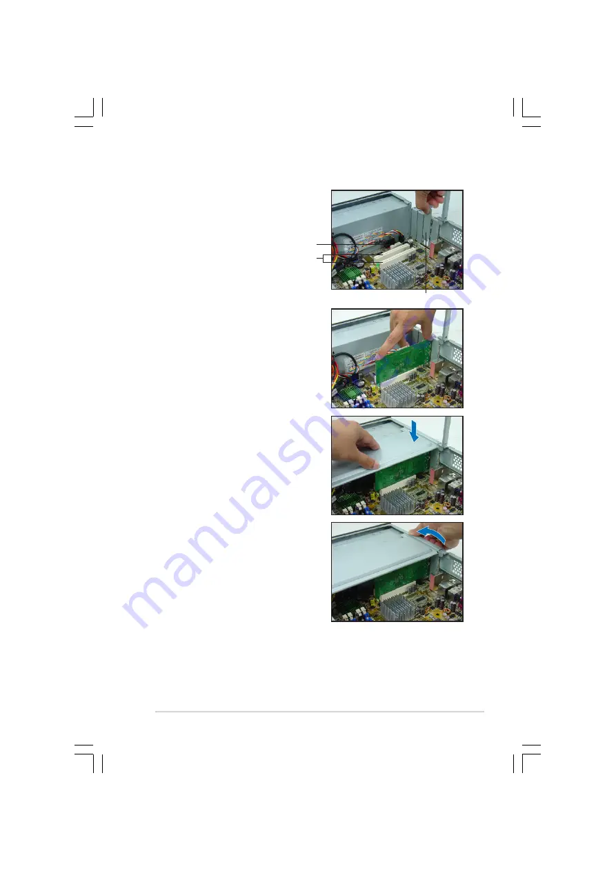
3.

Remove the metal cover opposite
the slot that you intend to use.

5.

If you have already installed a
hard disk drive, replace the
chassis support bracket;
otherwise, install other
components before replacing the
chassis support bracket.

4.

Align the card connector with the
slot and press firmly until the card
is completely seated on the slot.

P C I   s l o t s

P C I   s l o t s

P C I   s l o t s

P C I   s l o t s

P C I   s l o t s

P C I   E x p r e s s   x 1   s l o t

P C I   E x p r e s s   x 1   s l o t

P C I   E x p r e s s   x 1   s l o t

P C I   E x p r e s s   x 1   s l o t

P C I   E x p r e s s   x 1   s l o t

6.

Replace the expansion card lock
to secure the card to the chassis.

M e t a l   b r a c k e t

M e t a l   b r a c k e t

M e t a l   b r a c k e t

M e t a l   b r a c k e t

M e t a l   b r a c k e t

Содержание Pundit-PE3

Страница 1: ...Pundit Barebone System Model Pundit PE3 ...

Страница 2: ...OR CONDITIONS OF MERCHANTABILITY OR FITNESS FOR A PARTICULAR PURPOSE IN NO EVENT SHALL ASUS ITS DIRECTORS OFFICERS EMPLOYEES OR AGENTS BE LIABLE FOR ANY INDIRECT SPECIAL INCIDENTAL OR CONSEQUENTIAL DAMAGES INCLUDING DAMAGES FOR LOSS OF PROFITS LOSS OF BUSINESS LOSS OF USE OR DATA INTERRUPTION OF BUSINESS AND THE LIKE EVEN IF ASUS HAS BEEN ADVISED OF THE POSSIBILITY OF SUCH DAMAGES ARISING FROM ANY...

Страница 3: ... Before you proceed 2 2 2 3 Removing the covers 2 3 2 3 1 Removing the system cover 2 3 2 3 2 Removing the front panel assembly 2 4 2 4 Installing the CPU 2 5 2 5 Installing a DIMM 2 9 2 5 1 Memory configurations 2 9 2 5 2 Installing a DIMM 2 11 2 5 3 Removing a DIMM 2 11 2 6 Installing an expansion card 2 12 2 6 1 Expansion slots 2 12 2 6 2 Expansion card installation 2 12 2 7 Installing an optic...

Страница 4: ...erboard info Chapter 4 Motherboard info Chapter 4 Motherboard info Chapter 4 Motherboard info Chapter 4 Motherboard info 4 1 Motherboard overview 4 2 4 2 Jumpers 4 3 4 3 Connectors 4 5 4 3 1 Rear panel connectors 4 5 4 3 2 Internal connectors 4 5 Chapter 5 BIOS setup Chapter 5 BIOS setup Chapter 5 BIOS setup Chapter 5 BIOS setup Chapter 5 BIOS setup 5 1 Managing and updating your BIOS 5 2 5 1 1 AS...

Страница 5: ...4 Onboard Devices Configuration 5 17 2 4 5 PCI PnP 5 18 5 5 Power menu 5 20 5 5 1 Suspend Mode 5 20 5 5 2 Repost Video on S3 Resume 5 20 5 5 3 ACPI 2 0 Support 5 20 5 5 4 ACPI APIC Support 5 20 5 5 5 APM Configuration 5 21 5 5 6 Hardware Monitor 5 23 5 6 Boot menu 5 25 5 6 1 Boot Device Priority 5 25 5 6 2 Boot Settings Configuration 5 26 5 6 3 Security 5 27 5 7 Exit menu 5 30 Appendix Appendix Ap...

Страница 6: ...ry to correct the interference by one or more of the following measures Reorient or relocate the receiving antenna Increase the separation between the equipment and receiver Connect the equipment to an outlet on a circuit different from that to which the receiver is connected Consult the dealer or an experienced radio TV technician for help Canadian Department of Communications Statement Canadian ...

Страница 7: ...ay from connectors slots sockets and circuitry Avoid dust humidity and temperature extremes Do not place the product in any area where it may become wet Place the product on a stable surface If you encounter technical problems with the product contact a qualified service technician or your retailer Lithium Ion Battery Warning Lithium Ion Battery Warning Lithium Ion Battery Warning Lithium Ion Batt...

Страница 8: ...uction Chapter 1 System introduction Chapter 1 System introduction Chapter 1 System introduction This chapter gives a general description of the barebone system The chapter lists the system features including introduction on the front and rear panel and internal components 2 2 2 2 2 Chapter 2 Basic installation Chapter 2 Basic installation Chapter 2 Basic installation Chapter 2 Basic installation ...

Страница 9: ...NOTE NOTE Tips and additional information to aid in completing a task Typography Typography Typography Typography Typography Bold text Bold text Bold text Bold text Bold text Indicates a menu or an item to select Italics Used to emphasize a word or a phrase Key Keys enclosed in the less than and greater than sign means that you must press the enclosed key Example Enter means that you must press th...

Страница 10: ...it 2 2 2 2 2 Accessories Accessories Accessories Accessories Accessories Foot stand and screw 1 pair for vertical placement Rubber stand x 4 for horizontal placement Hard disk drive screw x 8 Optical drive screw x 2 Rubber washer x 8 3 3 3 3 3 Cables Cables Cables Cables Cables AC power cable IDE cable Serial ATA signal cable x 2 4 4 4 4 4 Support CD Support CD Support CD Support CD Support CD 5 5...

Страница 11: ...t PE3 ASUS Pundit PE3 ASUS Pundit PE3 Chapter 1 System introduction This chapter gives a general description of the barebone system The chapter lists the system features including introduction on the front and rear panel and internal components ...

Страница 12: ...so you can maximize your desktop space With these and many more the Pundit PE3 definitely delivers the cutting edge technology for your computing and multimedia needs 1 2 Front panel The front panel includes the system and audio control buttons and LEDs 1 1 1 1 1 Power button Power button Power button Power button Power button Press this button to turn the system on or off 2 2 2 2 2 Power LED Powe...

Страница 13: ...supports the S PDIF feature 6 6 6 6 6 Microphone port Microphone port Microphone port Microphone port Microphone port This Mic pink port connects a microphone 7 7 7 7 7 4 pin IEEE 1394a port 4 pin IEEE 1394a port 4 pin IEEE 1394a port 4 pin IEEE 1394a port 4 pin IEEE 1394a port This port provides high speed connectivity for IEEE 1394a compliant audio video devices storage peripherals and other PC ...

Страница 14: ... the function of this port becomes Low Frequency Enhanced Output Center 8 8 8 8 8 Metal bracket lock Metal bracket lock Metal bracket lock Metal bracket lock Metal bracket lock Secures the expansion slot card metal brackets 9 9 9 9 9 Voltage selector Voltage selector Voltage selector Voltage selector Voltage selector Allows you to adjust the system input voltage according to the voltage supply in ...

Страница 15: ...Audio ports function variation Audio ports function variation Audio ports function variation Audio ports function variation The functions of the Line Out Line In and Microphone ports change when you select the 6 channel configuration Refer to the table below for audio ports function variation Low Frequency Enhanced P o r t P o r t P o r t P o r t P o r t Headphone 2 Channel Headphone 2 Channel Hea...

Страница 16: ...Metal bracket lock 11 LGA775 socket under the CPU fan and heatsink assembly 12 CPU fan and heatsink assembly 13 DIMM sockets 1 4 Internal components The illustration below is the internal view of the system when you remove the top cover and the chassis support bracket The installed components are labeled for your reference Proceed to Chapter 2 for instructions on installing additional system compo...

Страница 17: ...ASUS Pundit PE3 ASUS Pundit PE3 ASUS Pundit PE3 ASUS Pundit PE3 ASUS Pundit PE3 Chapter 2 Basic installation This chapter provides step by step instructions on how to install components in the system ...

Страница 18: ...wing precautions before you install components into the system The system motherboard comes with an onboard standby power LED This LED lights up to indicate that the system is ON in sleep mode or in soft off mode and not powered OFF Unplug the power cable from the power outlet and make sure that the standby power LED is OFF before installing any system component Use a grounded wrist strap or touch...

Страница 19: ... 3 1 2 3 1 2 3 1 2 3 1 Removing the system cover Removing the system cover Removing the system cover Removing the system cover Removing the system cover To remove the cover and metal chassis support 1 On the rear panel locate the two thumb screws that secure the cover to the chassis 4 Lift the system cover then set aside 5 Lift the expansion card lock to a 90º 100º angle 6 Lift the chassis support...

Страница 20: ... front panel assembly Removing the front panel assembly To remove the front panel assembly 4 Swing the left edge of the front panel assembly outward 1 Place the system vertically 2 Locate the front panel assembly hooks 3 Pull the hooks outward to release the front panel assembly 5 Unhook the hinge like tabs from the holes on the right side of the chassis to detach Do not use too much force when re...

Страница 21: ...ontact your retailer immediately if you see any damage to the socket contacts motherboard components ASUS will shoulder the cost of repair only if the damage is shipment transit related The product warranty does not cover damage to the socket contacts resulting from incorrect CPU installation or removal CPU Socket 775 2 Press the load lever with your thumb A then move it to the left B until it is ...

Страница 22: ...refinger to a 100º angle A then push the PnP cap from the load plate window to remove B 5 Position the CPU over the socket making sure that the gold triangle is on the bottom left corner of the socket The socket alignment key should fit into the CPU notch Alignment key Alignment key Alignment key Alignment key Alignment key Gold triangle mark Gold triangle mark Gold triangle mark Gold triangle mar...

Страница 23: ...tation DO NOT force the CPU into the socket to prevent bending the connectors on the socket and damaging the CPU 6 Close the load plate A then push the load lever B until it snaps into the retention tab A B The motherboard supports Intel Pentium 4 LGA775 processors with Hyper Threading Technology Refer to the Appendix for more information ...

Страница 24: ...ners match the holes on the motherboard Orient the heatsink and fan assembly such that the CPU fan cable is closest to the CPU fan connector Fastener Fastener Fastener Fastener Fastener Motherboard hole Motherboard hole Motherboard hole Motherboard hole Motherboard hole Narrow end Narrow end Narrow end Narrow end Narrow end of the groove of the groove of the groove of the groove of the groove 2 Pu...

Страница 25: ...MM_A2 DIMM_A1 and DIMM_A2 Channel B Channel B Channel B Channel B Channel B DIMM_B1 and DIMM_B2 DIMM_B1 and DIMM_B2 DIMM_B1 and DIMM_B2 DIMM_B1 and DIMM_B2 DIMM_B1 and DIMM_B2 Installing DDR DIMMS other than the recommended configurations may cause memory sizing error or system boot failure Use any of the recommended configurations in the table on the next page Install only identical identical ide...

Страница 26: ... SAMSUNG SS K4H560838F TCCC 3 512 MB SAMSUNG M368L6423FTN CCC SAMSUNG DS K4H560838F TCCC 256 MB Hynix HYMD232646B8J D43 AA Hynix SS HY5DU56822BT D43 3 512 MB Hynix HYMD264646B8J D43 AA Hynix DS HY5DU56822BT D43 256 MB MICRON MT8VDDT3264AG 40BCB MICRON SS MT46V32M8TG 5BC 512 MB MICRON MT16VDDT6464AG 40BCB MICRON DS MT46V32M8TG 5BC 256 MB Infineon HYS64D32300GU 5 B Infineon SS HYB25D256800BT 5B 3 51...

Страница 27: ...nto the socket until the retaining clips snap back in place and the DIMM is properly seated 2 Remove the DIMM from the socket Unlocked Unlocked Unlocked Unlocked Unlocked retaining clip retaining clip retaining clip retaining clip retaining clip DDR DIMM notch DDR DIMM notch DDR DIMM notch DDR DIMM notch DDR DIMM notch L o c k e d L o c k e d L o c k e d L o c k e d L o c k e d retaining clip reta...

Страница 28: ...motherboard has two PCI and one PCI Express x1 slots The following sub sections describe the slots and the expansion cards that they support 2 6 1 2 6 1 2 6 1 2 6 1 2 6 1 Expansion slots Expansion slots Expansion slots Expansion slots Expansion slots PCI slots PCI slots PCI slots PCI slots PCI slots The PCI slots support cards such as a LAN card SCSI card USB card and other cards that comply with ...

Страница 29: ...se install other components before replacing the chassis support bracket 4 Align the card connector with the slot and press firmly until the card is completely seated on the slot PCI slots PCI slots PCI slots PCI slots PCI slots PCI Express x1 slot PCI Express x1 slot PCI Express x1 slot PCI Express x1 slot PCI Express x1 slot 6 Replace the expansion card lock to secure the card to the chassis Met...

Страница 30: ...rt 13 Numeric Data Processor 14 Primary IDE Channel These IRQs are usually available for ISA or PCI devices IRQ assignments for the system motherboard IRQ assignments for the system motherboard IRQ assignments for the system motherboard IRQ assignments for the system motherboard IRQ assignments for the system motherboard A A A A A B B B B B C C C C C D D D D D E E E E E F F F F F G G G G G H H H H...

Страница 31: ...e Audio cable Audio cable Audio cable Audio cable and plug and plug and plug and plug and plug 5 Connect the IDE cable to the IDE interface at the back of the drive Match the red stripe on the cable with Pin 1 on the IDE interface 6 Connect the optical drive audio cable to the 4 pin connector at the back of the optical drive To install an optical drive 1 Remove the front panel assembly following t...

Страница 32: ...he optical drive Uninstalling the optical drive Uninstalling the optical drive In the future you may have to upgrade or replace a defective optical drive To uninstall the optical drive 1 Remove the front panel assembly following the instructions in section 2 3 2 Removing the front panel assembly 2 Locate the optical drive screw lock 4 Disconnect the IDE audio and power cables and plugs from the ba...

Страница 33: ... drive in the place 2 8 2 2 8 2 2 8 2 2 8 2 2 8 2 SATA hard disk drive installation SATA hard disk drive installation SATA hard disk drive installation SATA hard disk drive installation SATA hard disk drive installation To install a SATA hard disk drive When installing o n e o n e o n e o n e o n e hard disk drive install it on the upper HDD bay 1 Insert the rubber washers to the HDD screws Refer ...

Страница 34: ...rd See page 4 6 for the location of the SATA connectors 4 Connect the 15 pin SATA power plug from the power supply unit to the power connector at the back of the drive 5 Place the HDD on the tray Make sure that the HDD screws are aligned with the screw holes and rails 6 When the HDD screws align with the screw rails push the drive carefully until it is completely flushed on the bay The HDD screw l...

Страница 35: ...stripe on the cable with Pin 1 on the IDE interface 3 Connect a power cable from the power supply unit to the power connector at the back of the drive 4 Follow steps 5 to 6 of the previous section to complete installation 2 8 4 2 8 4 2 8 4 2 8 4 2 8 4 Uninstalling a hard disk drive Uninstalling a hard disk drive Uninstalling a hard disk drive Uninstalling a hard disk drive Uninstalling a hard disk...

Страница 36: ...ng the front panel assembly If you installed an optical drive you must remove the optical drive bay cover before you replace the front panel assembly To remove the optical drive bay cover 1 Locate the optical drive bay cover hook locks at the back of the front panel assembly The photo on the right shows the front panel assembly without the optical drive bay cover 2 Press one lock inward A then pus...

Страница 37: ...irection of the front panel until it fits in place 4 Replace the cover screws 2 9 2 2 9 2 2 9 2 2 9 2 2 9 2 Replacing the system cover Replacing the system cover Replacing the system cover Replacing the system cover Replacing the system cover To replace the metal chassis support 2 Match and insert the hooks of the cover to the elongated holes on the side of the chassis All eight hooks four hooks o...

Страница 38: ...ot stands 1 Lay the system on its side on a flat stable and elevated surface then locate two screw holes on the left side of the system 2 Extend the left side of the system at least 3 cm from the edge of surface to facilitate installation 3 Position the foot stand on the chassis side until their screw holes align 4 Drive in a screw to secure the footstand to the chassis 5 Repeat steps 3 to 4 to in...

Страница 39: ...io Device Camera Camera Camera Camera Camera 2 11 Selecting the voltage The system s power supply unit has a 115 V 230 V voltage selector switch located beside the power connector Use this switch to select the appropriate system input voltage according to the voltage supply in your area If the voltage supply in your area is 100 127 V set the switch to 115 V If the voltage supply in your area is 20...

Страница 40: ...Line Out Recorder Recorder Recorder Recorder Recorder M i c M i c M i c M i c M i c VGA monitor VGA monitor VGA monitor VGA monitor VGA monitor Card reader Card reader Card reader Card reader Card reader P P P P Power outlet ower outlet ower outlet ower outlet ower outlet Printer Printer Printer Printer Printer Serial mouse Serial mouse Serial mouse Serial mouse Serial mouse P S 2 K B P S 2 K B P ...

Страница 41: ...ASUS Pundit PE3 ASUS Pundit PE3 ASUS Pundit PE3 ASUS Pundit PE3 ASUS Pundit PE3 Chapter 3 Getting started This chapter helps you power up the system and install drivers and utilities from the support CD ...

Страница 42: ...em features 3 2 1 3 2 1 3 2 1 3 2 1 3 2 1 Running the support CD Running the support CD Running the support CD Running the support CD Running the support CD Place the support CD to the optical drive The CD automatically displays the Drivers Drivers Drivers Drivers Drivers menu if Autorun is enabled in your computer Motherboard settings and hardware options vary Use the setup procedures presented i...

Страница 43: ...t components You can install this utility using three different modes interactive silent or unattended preload Installing the driver in interactive mode requires user input during installation User input is not required when installing the driver in silent or unattended preload modes Refer to the online help or readme file that came with the utility for details Realtek Audio Driver Realtek Audio D...

Страница 44: ...the fan speed CPU temperature and system voltages and alerts you of any detected problems This utility helps you keep your computer in healthy operating condition ASUS Update ASUS Update ASUS Update ASUS Update ASUS Update The ASUS Update utility allows you to update the motherboard BIOS in a Windows environment This utility requires an Internet connection either through a network or an Internet S...

Страница 45: ...ft DirectX 9 0c Microsoft DirectX 9 0c Microsoft DirectX 9 0c Installs the Microsoft DirectX 9 0c driver Anti Virus Utility Anti Virus Utility Anti Virus Utility Anti Virus Utility Anti Virus Utility The anti virus application scans identifies and removes computer viruses View the online help for detailed information ADOBE Acrobat Reader ADOBE Acrobat Reader ADOBE Acrobat Reader ADOBE Acrobat Read...

Страница 46: ...information The icons on the top right corner of the screen give additional information on the motherboard and the contents of the support CD Click an icon to display the specified information Motherboard Info Motherboard Info Motherboard Info Motherboard Info Motherboard Info Displays the general specifications of the motherboard Browse this CD Browse this CD Browse this CD Browse this CD Browse ...

Страница 47: ...nical support form Technical support form Technical support form Technical support form Displays the ASUS Technical Support Request Form that you have to fill out when requesting technical support Filelist Filelist Filelist Filelist Filelist Displays the contents of the support CD and a brief description of each in text format ...

Страница 48: ...3 8 3 8 3 8 3 8 3 8 Chapter 3 Getting started Chapter 3 Getting started Chapter 3 Getting started Chapter 3 Getting started Chapter 3 Getting started ...

Страница 49: ...S Pundit PE3 ASUS Pundit PE3 ASUS Pundit PE3 Motherboard info Chapter 4 This chapter gives information about the motherboard that comes with the system This chapter includes the motherboard layout jumper settings and connector locations ...

Страница 50: ...FWH 4Mb ATX12V1 AAFP1 DDR DIMM_A1 64 bit 240 pin module KBPWR1 SB_PWR1 USBPW34 USBPW12 F_PANEL1 USB78 USB56 USBPW56 USBPW78 CLRTC1 SATA1 PCI1 Intel MCH 915GL Intel ICH6 DDR DIMM_A2 64 bit 240 pin module DDR DIMM_B1 64 bit 240 pin module DDR DIMM_B2 64 bit 240 pin module CHA_FAN1 CPU_FAN1 PRI_IDE1 ALC655 EATXPWR1 SATA2 PCI2 SPDIF_OUT1 Intel LAN Chip R LGA775 PS 2KBMS T Mouse B Keyboard Below Mic In...

Страница 51: ...te time and system setup parameters by erasing the CMOS RTC RAM data The onboard button cell battery powers the RAM data in CMOS which include system setup information such as system passwords To erase the RTC RAM 1 Turn OFF the computer and unplug the power cord 2 Remove the onboard battery 3 Move the jumper cap from pins 1 2 default to pins 2 3 Keep the cap on pins 2 3 for about 5 10 seconds the...

Страница 52: ...ower mode The USB device wake up feature requires a power supply that can provide 500mA on the 5VSB lead for each USB port otherwise the system will not power up The total current consumed must NOT exceed the power supply capability 5VSB whether under normal condition or in sleep mode 3 3 3 3 3 Keyboard power 3 pin KBPWR1 Keyboard power 3 pin KBPWR1 Keyboard power 3 pin KBPWR1 Keyboard power 3 pin...

Страница 53: ...or is for an Ultra DMA 100 66 33 signal cable The Ultra DMA 100 66 33 signal cable has three connectors a blue connector for the primary IDE connector on the motherboard a black connector for an Ultra DMA 100 66 33 IDE slave device optical drive hard disk drive and a gray connector for an Ultra DMA 100 66 33 IDE master device hard disk drive If you install an optical drive and an IDE HDD you must ...

Страница 54: ... max or a total of 1 A 2 22 A 26 64 W max at 12V Connect the fan cables to the fan connectors on the motherboard making sure that the black wire of each cable matches the ground pin of the connector Important notes on Serial ATA Important notes on Serial ATA Important notes on Serial ATA Important notes on Serial ATA Important notes on Serial ATA You must install Windows 2000 Service Pack 4 or the...

Страница 55: ...e covered hole on the Ultra DMA cable connector This prevents incorrect insertion when you connect the IDE cable 5 5 5 5 5 Internal audio connectors 4 pin CD1 AUX1 Internal audio connectors 4 pin CD1 AUX1 Internal audio connectors 4 pin CD1 AUX1 Internal audio connectors 4 pin CD1 AUX1 Internal audio connectors 4 pin CD1 AUX1 These connectors allow you to receive stereo audio input from audio sour...

Страница 56: ...ower supply are pre connected to these connectors If you have disconnected them during installation find the proper orientation and push down the plugs firmly to the connectors until they fit Important notes on the motherboard power requirements Important notes on the motherboard power requirements Important notes on the motherboard power requirements Important notes on the motherboard power requi...

Страница 57: ...anel 9 9 9 9 9 IEEE 1394 IEEE 1394 IEEE 1394 IEEE 1394 IEEE 1394a a a a a port connector 10 1 pin IE1394_2 orange port connector 10 1 pin IE1394_2 orange port connector 10 1 pin IE1394_2 orange port connector 10 1 pin IE1394_2 orange port connector 10 1 pin IE1394_2 orange This connector supports the 4 pin IEEE 1394 port in the system front panel Never connect a USB cable USB cable USB cable USB c...

Страница 58: ...t off button Yellow 2 pin PWRSW ATX power button soft off button Yellow 2 pin PWRSW ATX power button soft off button Yellow 2 pin PWRSW This connector is for the system power button Pressing the power button turns the system on or puts the system in sleep or soft off mode depending on the BIOS settings Pressing the power switch for more than four seconds while the system is ON turns the system OFF...

Страница 59: ...Pundit PE3 ASUS Pundit PE3 ASUS Pundit PE3 ASUS Pundit PE3 ASUS Pundit PE3 BIOS setup Chapter 5 This chapter tells how to change system settings through the BIOS Setup menus and describes the BIOS parameters ...

Страница 60: ...utput System BIOS setup 1 ASUS CrashFree BIOS 2 ASUS CrashFree BIOS 2 ASUS CrashFree BIOS 2 ASUS CrashFree BIOS 2 ASUS CrashFree BIOS 2 Updates the BIOS using the motherboard support CD when the BIOS file fails or gets corrupted 2 ASUS Update ASUS Update ASUS Update ASUS Update ASUS Update Updates the BIOS in Windows environment Refer to the corresponding sections for details on these utilities Sa...

Страница 61: ... ASUS Update ASUS Update ASUS Update ASUS Update ASUS Update See page 3 4 for the Utilities Utilities Utilities Utilities Utilities screen menu 3 The ASUS Update utility is copied to your system 5 1 2 5 1 2 5 1 2 5 1 2 5 1 2 ASUS Update utility ASUS Update utility ASUS Update utility ASUS Update utility ASUS Update utility The ASUS Update is a utility that allows you to manage save and update the ...

Страница 62: ...the Internet Updating the BIOS through the Internet To update the BIOS through the Internet 1 Launch the ASUS Update utility from the Windows desktop by clicking Start Start Start Start Start Programs Programs Programs Programs Programs ASUS ASUS ASUS ASUS ASUS ASUSUpdate ASUSUpdate ASUSUpdate ASUSUpdate ASUSUpdate ASUSUpdate ASUSUpdate ASUSUpdate ASUSUpdate ASUSUpdate The ASUS Update main window ...

Страница 63: ...Update ASUSUpdate ASUSUpdate ASUSUpdate ASUSUpdate ASUSUpdate The ASUS Update main window appears 2 Select Update BIOS from a Update BIOS from a Update BIOS from a Update BIOS from a Update BIOS from a file file file file file option from the drop down menu then click Next Next Next Next Next 4 From the FTP site select the BIOS version that you wish to download Click Next Next Next Next Next 5 Fol...

Страница 64: ... Press Del during the Power On Self Test POST to enter the Setup utility otherwise POST continues with its test routines If you wish to enter Setup after POST restart the system by pressing Ctrl Alt Delete or by pressing the reset button on the system chassis You can also restart by turning the system off and then back on Do this last option only if the first two failed The Setup program is design...

Страница 65: ...ROM ATA Third IDE Master Not Detected Fourth IDE Master Not Detected IDE Configuration System Information Use ENTER TAB or SHIFT TAB to select a field Use or to configure the System time 5 2 1 5 2 1 5 2 1 5 2 1 5 2 1 BIOS menu screen BIOS menu screen BIOS menu screen BIOS menu screen BIOS menu screen Navigation keys Navigation keys Navigation keys Navigation keys Navigation keys General help Gener...

Страница 66: ...2 7 5 2 7 5 2 7 5 2 7 5 2 7 Pop up window Pop up window Pop up window Pop up window Pop up window Select a menu item then press Enter to display a pop up window with the configuration options for that item 5 2 8 5 2 8 5 2 8 5 2 8 5 2 8 Scroll bar Scroll bar Scroll bar Scroll bar Scroll bar A scroll bar appears on the right side of a menu screen when there are items that do not fit on the screen Pr...

Страница 67: ... 5 3 2 5 3 2 5 3 2 5 3 2 5 3 2 System Date Day xx xx xxxx System Date Day xx xx xxxx System Date Day xx xx xxxx System Date Day xx xx xxxx System Date Day xx xx xxxx Allows you to set the system date System Time 11 51 19 System Date Thu 06 10 2004 Primary IDE Master ST320413A Primary IDE Slave Pioneer CD ROM ATA Third IDE Master Not Detected Fourth IDE Master Not Detected IDE Configuration System ...

Страница 68: ...able Media Device if your device is either a ZIP LS 120 or MO drive Configuration options Not Installed Auto CDROM ARMD LBA Large Mode Auto LBA Large Mode Auto LBA Large Mode Auto LBA Large Mode Auto LBA Large Mode Auto Enables or disables the LBA mode Setting to Auto enables the LBA mode if the device supports this mode and if the device was not previously formatted with LBA mode disabled Configu...

Страница 69: ...nfiguration options Disabled Enabled 5 3 4 5 3 4 5 3 4 5 3 4 5 3 4 IDE Configuration IDE Configuration IDE Configuration IDE Configuration IDE Configuration The items in this menu allow you to set or change the configurations for the IDE devices installed in the system Select an item then press Enter if you want to configure the item Onboard IDE Operate Mode Enhanced Mode Onboard IDE Operate Mode ...

Страница 70: ...e P ATA IDE Detect Time Out 35 IDE Detect Time Out 35 IDE Detect Time Out 35 IDE Detect Time Out 35 IDE Detect Time Out 35 Selects the time out value for detecting ATA ATAPI devices Configuration options 0 5 10 15 20 25 30 35 5 3 5 5 3 5 5 3 5 5 3 5 5 3 5 System Information System Information System Information System Information System Information This menu gives you an overview of the general sy...

Страница 71: ...SB Ports Legacy USB Support Auto USB 2 0 Controller Enabled USB 2 0 Controller Mode HiSpeed BIOS EHCI Hand off Enabled 5 4 Advanced menu The Advanced menu items allow you to change the settings for the CPU and other system devices USB Configuration CPU Configuration Chipset Onboard Devices Configuration PCI PnP Configure the USB support Enables USB host controllers USB Function 8 USB Ports USB Fun...

Страница 72: ...ions Full Speed HiSpeed BIOS EHCI Hand Off Disabled BIOS EHCI Hand Off Disabled BIOS EHCI Hand Off Disabled BIOS EHCI Hand Off Disabled BIOS EHCI Hand Off Disabled Allows you to enable support for operating systems without an EHCI hand off feature Configuration options Enabled Disabled 5 4 2 5 4 2 5 4 2 5 4 2 5 4 2 CPU Configuration CPU Configuration CPU Configuration CPU Configuration CPU Configu...

Страница 73: ...ally check the CPU s capability to enable the C1E support In C1E mode the CPU power consumption is lower when idle Configuration options Auto Disabled CPU Internal Thermal Control Auto CPU Internal Thermal Control Auto CPU Internal Thermal Control Auto CPU Internal Thermal Control Auto CPU Internal Thermal Control Auto Disables or sets the CPU internal thermal control Configuration options Auto Di...

Страница 74: ...recharge 4 Clocks Controls the idle clocks after issuing a precharge command to the DDR SDRAM Configuration options 2 Clocks 3 Clocks 4 Clocks 5 Clocks DRAM RAS to CAS Delay 4 Clocks Controls the latency between the DDR SDRAM active command and the read write command Configuration options 2 Clocks 3 Clocks 4 Clocks 5 Clocks DRAM RAS Activate to Precharge Delay 15 Clocks Configuration options 4 Clo...

Страница 75: ...uration Onboard Devices Configuration Onboard Devices Configuration Onboard Devices Configuration Configure Win627EHF Super IO Chipset Onboard AC97 Controller Enabled Onboard 1394 Controller Enabled Onboard LAN Enabled LAN Boot ROM Disabled Serial Port1 Address 3F8 IRQ4 Parallel Port Address 378 Parallel Port Mode ECP ECP Mode DMA Channel DMA3 Parallel Port IRQ IRQ7 Enable or disable AC97 controll...

Страница 76: ... EPP ECP ECP Mode DMA Channel DMA3 Appears only when the Parallel Port Mode is set to ECP This item allows you to set the Parallel Port ECP DMA Configuration options DMA0 DMA1 DMA3 EPP Version 1 9 EPP Version 1 9 EPP Version 1 9 EPP Version 1 9 EPP Version 1 9 Allows selection of the Parallel Port EPP version This item appears only when the Parallel Port Mode Parallel Port Mode Parallel Port Mode ...

Страница 77: ...Latency Timer 64 PCI Latency Timer 64 PCI Latency Timer 64 PCI Latency Timer 64 PCI Latency Timer 64 Allows you to select the value in units of PCI clocks for the PCI device latency timer register Configuration options 32 64 96 128 160 192 224 248 Allocate IRQ to PCI VGA Yes Allocate IRQ to PCI VGA Yes Allocate IRQ to PCI VGA Yes Allocate IRQ to PCI VGA Yes Allocate IRQ to PCI VGA Yes When set to ...

Страница 78: ...o Repost Video on S3 Resume No Determines whether to invoke VGA BIOS post on S3 STR resume Configuration options No Yes 5 5 3 5 5 3 5 5 3 5 5 3 5 5 3 ACPI 2 0 Support No ACPI 2 0 Support No ACPI 2 0 Support No ACPI 2 0 Support No ACPI 2 0 Support No Allows you to add more tables for Advanced Configuration and Power Interface ACPI 2 0 specifications Configuration options No Yes 5 5 4 5 5 4 5 5 4 5 ...

Страница 79: ...te Power On By RTC Alarm Disabled Power On By RTC Alarm Disabled Power On By RTC Alarm Disabled Power On By RTC Alarm Disabled Power On By RTC Alarm Disabled Allows you to enable or disable RTC to generate a wake event When this item is set to Enabled the items RTC Alarm Date RTC Alarm Hour RTC Alarm Minute and RTC Alarm Second appear with set values Configuration options Disabled Enabled The succ...

Страница 80: ...des at least 1A on the 5VSB lead Configuration options Disabled Enabled Power On By PS 2 Keyboard Disabled Power On By PS 2 Keyboard Disabled Power On By PS 2 Keyboard Disabled Power On By PS 2 Keyboard Disabled Power On By PS 2 Keyboard Disabled Allows you to use specific keys on the keyboard to turn on the system This feature requires an ATX power supply that provides at least 1A on the 5VSB lea...

Страница 81: ...fficient system operation When this field is set to Enabled the CPU Fan Ratio CPU Fan Ratio CPU Fan Ratio CPU Fan Ratio CPU Fan Ratio item appears to allow selection of the appropriate fan speed ratio Configuration options Disabled Enabled The CPU Fan Ratio CPU Fan Ratio CPU Fan Ratio CPU Fan Ratio CPU Fan Ratio and CPU Target Temperature CPU Target Temperature CPU Target Temperature CPU Target Te...

Страница 82: ...xxxRPM or N A Chassis Fan Speed xxxxRPM or N A Chassis Fan Speed xxxxRPM or N A Chassis Fan Speed xxxxRPM or N A Chassis Fan Speed xxxxRPM or N A The onboard hardware monitor automatically detects and displays the chassis fan speed in rotations per minute RPM If the fan is not connected to the chassis the specific field shows N A VCORE Voltage 3 3V Voltage 5V Voltage 12V Voltage VCORE Voltage 3 3V...

Страница 83: ... Device 1st Floppy Drive 1st 3rd Boot Device 1st Floppy Drive 1st 3rd Boot Device 1st Floppy Drive 1st 3rd Boot Device 1st Floppy Drive 1st 3rd Boot Device 1st Floppy Drive These items specify the boot device priority sequence from the available devices The number of device items that appears on the screen depends on the number of devices installed in the system Configuration options xxxxx Drive D...

Страница 84: ...ed Enabled Full Screen Logo Enabled Full Screen Logo Enabled Full Screen Logo Enabled Full Screen Logo Enabled Full Screen Logo Enabled This allows you to enable or disable the full screen logo display feature Configuration options Disabled Enabled Set this item to Enabled to use the ASUS MyLogo feature Add On ROM Display Mode Keep Current Add On ROM Display Mode Keep Current Add On ROM Display Mo...

Страница 85: ...Save and Exit ESC Exit Security Settings Supervisor Password Not Installed User Password Not Installed Change Supervisor Password Enter to change password Enter again to disabled password Change Supervisor Password Change Supervisor Password Change Supervisor Password Change Supervisor Password Change Supervisor Password Select this item to set or change the supervisor password The Supervisor Pass...

Страница 86: ...ers for information on how to erase the RTC RAM User Access Level Full Access User Access Level Full Access User Access Level Full Access User Access Level Full Access User Access Level Full Access This item allows you to select the access restriction to the Setup items Configuration options No Access View Only Limited Full Access No Access No Access No Access No Access No Access prevents user acc...

Страница 87: ...the password box that appears type a password composed of at least six letters and or numbers then press Enter 3 Confirm the password when prompted The message Password Installed appears after you set your password successfully To change the user password follow the same steps as in setting a user password Clear User Password Clear User Password Clear User Password Clear User Password Clear User P...

Страница 88: ...onfirmation before exiting Discard Changes Discard Changes Discard Changes Discard Changes Discard Changes This option allows you to discard the selections you made and restore the previously saved values After selecting this option a confirmation appears Select Y e s Y e s Y e s Y e s Y e s to discard any changes and load the previously saved values If you attempt to exit the Setup program withou...

Страница 89: ...ts This option allows you to load the default values for each of the parameters on the Setup menus When you select this option or if you press F5 a confirmation window appears Select Y e s Y e s Y e s Y e s Y e s to load default values Select Exit Save Changes Exit Save Changes Exit Save Changes Exit Save Changes Exit Save Changes or make other changes before saving the values to the non volatile ...

Страница 90: ...5 32 5 32 5 32 5 32 5 32 Chapter 5 BIOS setup Chapter 5 BIOS setup Chapter 5 BIOS setup Chapter 5 BIOS setup Chapter 5 BIOS setup ...

Отзывы: