manualshive.com logo in svg
background image

E-2

    • If the punch unit is open, do not carry the front.

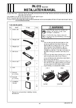
2. Installation procedures

Note:

When mounting the punch kit, mount it before 
mounting the finisher to the main unit.

(1) Turn OFF the power switch and unplug the 

power cord from the power outlet.

(2) Remove protective tape and protective materials 

and take out accessory parts.

(3) If the Finisher FS-533 is mounted on the main 

unit, remove the finisher.

Note:

<C554e/C454e/C364e/C284e/C224e/C554/C454/
C364/C284/C224/C368/C308/554e/454e/364e/
284e/224e>

See the installation manual for the Finisher FS-
533 for removal instructions.

<367/287/227>

See the installation manual for the Mount Kit/Fin-
isher MK-602/FS-533 for removal instructions.

(4) Attach the three supplied seals to fill the square 

holes in the output tray of the main unit as shown 
in the illustration.

(5) Place the punch unit upside down, then install 

the stopper arm at the position shown in the illus-
tration. (One supplied screw A)

Do not carry the unit while open.

Содержание PK-519

Страница 1: ...your machine to follow the installation procedure This does not cause any significant change or problem with the proce dure If none of the later steps instruct you to use the parts including screw and cover that you removed following the instructions described in this manual discard them After installing the Punch Kit PK 519 to the Fin isher FS 533 check again that the punch unit is securely locke...

Страница 2: ...ove the finisher Note C554e C454e C364e C284e C224e C554 C454 C364 C284 C224 C368 C308 554e 454e 364e 284e 224e See the installation manual for the Finisher FS 533 for removal instructions 367 287 227 See the installation manual for the Mount Kit Fin isher MK 602 FS 533 for removal instructions 4 Attach the three supplied seals to fill the square holes in the output tray of the main unit as shown ...

Страница 3: ...isher Three screws 8 Remove the knockout from the cover removed in step 7 with nippers 9 Remove the screw shown in the illustration from the finisher 10 While being careful with harness routing slide the plate shown in the illustration in the PK direction Insert the tab located at the end of the plate into the rectangular hole on the frame 11 Secure the plate with the screw removed in step 9 Tab ...

Страница 4: ...part from the front rail then install by sliding in the PK direction One screw 15 Fit the two tabs on the finisher into the rectan gular holes on the punch unit 16 Secure the punch unit with the supplied screw B 17 Connect the two connectors of the punch unit to the board of the finisher 18 Align the slit of the stopper arm with the pin on the stopper pin so that the punch unit is secured to the f...

Страница 5: ...s shown in the illustration One screw F supplied with the MK 602 21 Install the finisher to the main unit Note C554e C454e C364e C284e C224e C554 C454 C364 C284 C224 C368 C308 554e 454e 364e 284e 224e See the installation manual for the Finisher FS 533 for installation instructions 367 287 227 See the installation manual for the Mount Kit Fin isher MK 602 FS 533 for installation instructions Note ...

Страница 6: ... below the rail cover c Secure the rail cover with the screw front side and the shoulder screw rear side Note Use the shoulder screw and the screw supplied with the finisher 24 Slide the finisher into the main unit 25 Affixing the label Note Perform the following steps only when necessary a Slide the finisher by pulling its lever b By turning the lever of the punch unit rotate the punch unit Affix...

Страница 7: ...en be sure to turn off the main power after exiting the Service Mode screen and wait for 10 seconds or more before turning on 4 Adjustment procedures Punch hole deviance adjustment 1 Make a copy in the punch mode Refer to the User s Guide CD 2 Fold the copy into halves and check for possible deviation in the punch hole positions Specifications 0 2 0 mm Note If the positional deviation of the punch...

Страница 8: ...ke a copy in the punch mode Refer to the User s Guide CD 2 Check the tilt of the output paper Note If it tilts follow the procedures below for punch loop adjustment 3 Display the Service Mode screen For details of how to display the Service Mode screen see the service manual 4 Touch Finisher 5 Touch FS FN adjustment 6 Touch Punch Regist Loop Size 7 Set the correction value using the keys To make l...

Отзывы: