


2-26
Chapter 2: Hardware information
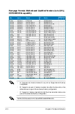
2. Position the motherboard
I/O side toward the chassis
rear panel and install the
motherboard to the chassis.
3. Thread the LCD Poster cable
through the opening until its
stopper snaps into place.
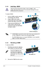
4. Plug the LCD Poster cable into
the onboard connector labeled
LCD_CON.
5. This photo shows the LCD
Poster installed. Place the
device wherever you can
monitor the screen.
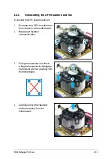
1. Install the I/O shield to the chassis rear panel. Orient the I/O shield so that
the openings of the ports fit the motherboard rear ports. Snaps the I/O shield
into place.
2.7.2
I/O shield and LCD Poster Installation
Be cautious when installing
the I/O shield. The I/O shield
edge springs may damage
the I/O ports.
Содержание PCI/E-P54NP4
Страница 1: ...Motherboard Rampage Formula ...
Страница 14: ...xiv ...
Страница 16: ...ROG Rampage Formula Chapter summary 1 1 1 Welcome 1 1 1 2 Package contents 1 1 1 3 Special features 1 2 ...
Страница 66: ...ROG Rampage Formula Chapter summary 3 3 1 Starting up for the first time 3 1 3 2 Turning off the computer 3 2 ...
Страница 114: ...4 44 Chapter 4 BIOS setup ...


