background image

ASUS P8Z77-V LK2

6-11

Chapter 6

5. 

Select all and click 

Next 

for 

Custom Setup

.


6. 

Click 

Install 

to proceed the installation.

7. 

Click 

Yes 

to restart your system, and for the newly installed Intel

®

 Smart Connect 

Technology to take effect.

Using the Intel

®

 Smart Connect Technology

• 

Before the system goes to sleep mode, ensure to keep your applications on the    


desktop, and enter the applications, passwords. 

• 

Ensure that the internet is in connection when enabling the Intel

®

 Smart Connect    


Technology.

1. 

Click 

Start > All Programs > Intel > Intel

®

 Smart Connect Technology

.

2. 

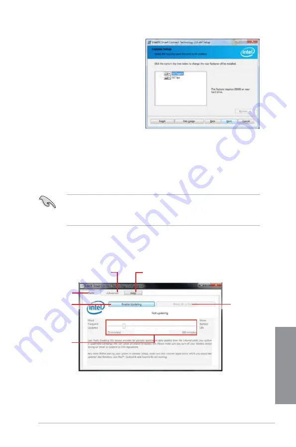
In the 

Basic 

tab, click 

Enable Updating

. When enabled, the 

Advanced 

tab is 

available for advanced function settings. 

Click to enable 

or disable the 

function

When the scroll bar 

is activated, adjust 

the waking up time 

period for Internet 

data update. 

Click to configure 

the basic settings

The Advanced tab is activated 

when updating is enabled

Click to view version 

information and help topics

When updating is 

enabled, click to 

reset all settings 

to default.

Содержание P8Z77-V LK2

Страница 1: ...Motherboard P8Z77 V LK2 ...

Страница 2: ...ective companies and are used only for identification or explanation and to the owners benefit without intent to infringe Offer to Provide Source Code of Certain Software This product contains copyrighted software that is licensed under the General Public License GPL under the Lesser General Public License Version LGPL and or other Free Open Source Software Licenses Such software in this product i...

Страница 3: ...19 1 2 7 Internal connectors 1 19 Basic Installation 2 1 Building your PC system 2 1 2 1 1 Motherboard installation 2 1 2 1 2 CPU installation 2 4 2 1 3 CPU heatsink and fan assembly installation 2 6 2 1 5 ATX Power connection 2 9 2 1 6 SATA device connection 2 10 2 1 7 Expansion Card installation 2 11 2 2 Motherboard rear and audio connections 2 12 2 2 1 Rear I O connection 2 12 2 2 2 Audio I O c...

Страница 4: ... Updating BIOS 3 33 3 10 1 ASUS Update utility 3 33 3 10 2 ASUS EZ Flash 2 utility 3 36 3 10 3 ASUS CrashFree BIOS 3 utility 3 37 3 10 4 ASUS BIOS Updater 3 38 Software support 4 1 Installing an operating system 4 1 4 2 Support DVD information 4 1 4 2 1 Running the support DVD 4 1 4 2 2 Obtaining the software manuals 4 2 4 3 Software information 4 3 4 3 1 AI Suite II 4 3 4 3 2 TurboV EVO 4 4 4 3 3...

Страница 5: ...during Windows OS installation 5 9 5 2 4 Using a USB floppy disk drive 5 10 Intel technologies 6 1 Introduction to Intel 2012 Desktop responsiveness technologies 6 1 6 1 1 System Requirements for Intel 2012 Desktop responsiveness technologies 6 1 6 1 2 Intel Smart Response Technology 6 3 6 1 3 Intel Rapid Start Technology 6 4 6 1 4 Intel Smart Connect Technology 6 10 Multiple GPU support 7 1 7 1 A...

Страница 6: ...your area If you are not sure about the voltage of the electrical outlet you are using contact your local power company If the power supply is broken do not try to fix it by yourself Contact a qualified service technician or your retailer Operation safety Before installing the motherboard and adding devices on it carefully read all the manuals that came with the package Before using the product en...

Страница 7: ...is chapter describes the contents of the support DVD that comes with the motherboard package and the software Chapter 5 RAID support This chapter describes the RAID configurations Chapter 6 Intel Technologies This chapter is an introduction to the Intel 2012 desktop responsiveness technologies included with the motherboard Chapter 7 Multiple GPU technology support This chapter describes how to ins...

Страница 8: ...lete a task IMPORTANT Instructions that you MUST follow to complete a task NOTE Tips and additional information to help you complete a task Typography Bold text Indicates a menu or an item to select Italics Used to emphasize a word or a phrase Key Keys enclosed in the less than and greater than sign means that you must press the enclosed key Example Enter means that you must press the Enter or Ret...

Страница 9: ...rts RGB with max resolution up to 2048 x 1536 75Hz Maximum shared memory of 1696MB Multi GPU support Supports ATI Quad GPU CrossFireXTM Technology Supports Lucid MVP Technology LucidLogix Virtu Universal MVPTM supports Windows 7 Operating Systems Expansion slots 1 x PCI Express 3 0 2 0 x16 slot blue at x16 mode 1 x PCI Express 2 0 x16 slot black max at x4 mode compatible with PCIe x1 and x4 device...

Страница 10: ...Boost TurboV GPU Boost AI Charger Disk Unlocker AI Suite II Anti Surge Low EMI Solution 100 Solid Capacitors ASUS Quiet Thermal Solution ASUS Fanless Design Stylish Heatsink solution ASUS Fan Xpert ASUS EZ DIY ASUS UEFI BIOS ASUS CrashFree BIOS 3 ASUS EZ Flash 2 ASUS My Logo 2 ASUS exclusive overclocking features Precision Tweaker 2 vCore Adjustable CPU voltage at 0 005V increment vCCSA 190 step s...

Страница 11: ...pin 2 x Chassis Fan connectors 4 pin 1 x Power Fan connector 3 pin 1 x Front panel audio connector 1 x S PDIF Out Header 1 x 24 pin ATX Power connector 1 x 4 pin ATX 12V Power connector 1 x System Panel 1 x Clear CMOS jumper BIOS features 64 Mb Flash ROM UEFI AMI BIOS PnP DMI2 0 WfM2 0 SM BIOS 2 7 ACPI 4 0a Multi language BIOS ASUS EZ Flash 2 ASUS CrashFree BIOS 3 F12 PrintScreen F3 Shotcut Functi...

Страница 12: ...e above items is damaged or missing contact your retailer The illustrated items above are for reference only Actual product specifications may vary with different models UserManual ASUS P8Z77 V LK2 motherboard User Guide Support DVD 2 x Serial ATA 6 0 Gb s cables 1 x I O shield P8Z77 V LK2 ...

Страница 13: ...ips cross screwdriver PC chassis Power supply unit Intel LGA1155 CPU Intel LGA1155 CPU Fan DIMM SATA hard disk drive SATA optical disc drive optional Graphics card optional The tools and components in the table above are not included in the motherboard package ...

Страница 14: ...xiv ...

Страница 15: ... Channel DDR3 2400 O C 2200 O C 2133 O C 1866 O C 1600 1333 1066 Support The motherboard supports DDR3 memory that features data transfer rates of 2400 O C 2200 O C 2133 O C 1866 O C 1600 1333 1066 MHz to meet the higher bandwidth requirements of the latest 3D graphics multimedia and Internet applications The dual channel DDR3 architecture enlarges the bandwidth of your system memory to boost syst...

Страница 16: ...I Express 3 0 PCIe 3 0 is the latest PCI Express bus standard with improved encoding schemes that provide twice the performance of current PCIe 2 0 Total bandwidth for a x16 link reaches a maximum of 32GB s double the 16GB s of PCIe 2 0 in x16 mode As such PCIe 3 0 provides users unprecedented data speeds combined with the convenience and seamless transition offered by complete backward compatibil...

Страница 17: ...ws users to fully utilize 3x faster video conversion with Intel Quick Sync Video technology while retaining high end 3D rendering and gaming performance provided by both NVIDIA and AMD graphic cards When the discrete graphic card is not required power consumption goes automatically down to near zero making the system more environmentally friendly For users searching for perfection LucidLogix Virtu...

Страница 18: ...se a grounded wrist strap or touch a safely grounded object or a metal object such as the power supply case to avoid damaging them due to static electricity Hold components by the edges to avoid touching the ICs on them Whenever you uninstall any component place it on a grounded antistatic pad or in the bag that came with the component Before you install or remove any component switch off the ATX ...

Страница 19: ...PWR_FAN Lithium Cell CMOS Power Super I O DIGI VRM ASM 1442 RTL 8111F COM1 8Mb BIOS SB_PWR SATA3G_3 SATA3G_2 SATA3G_1 SATA3G_4 SATA6G_2 SATA6G_1 CLRTC 20 8cm 8 2in 30 5cm 12 0in Intel Z77 DDR3 DIMM_A1 64bit 240 pin module DDR3 DIMM_A2 64bit 240 pin module DDR3 DIMM_B1 64bit 240 pin module DDR3 DIMM_B2 64bit 240 pin module ASM 1083 ALC 887 EATXPWR LGA1155 AUDIO KBMS LAN_USB12 LAN3_12 USB34 HDMI F_P...

Страница 20: ...SB3_34 1 24 6 Intel Z77 Serial ATA 3 0 Gb s connectors 7 pin SATA3G_1 4 blue 1 25 7 Onboard LED SB_PWR 1 19 8 Intel Z77 Serial ATA 6 0 Gb s connectors 7 pin SATA6G_1 2 gray 1 20 9 System panel connector 10 1 pin F_PANEL 1 24 10 Speaker connector 4 pin SPEAKER 1 28 11 USB 2 0 connectors 10 1 pin USB56 USB78 1 21 12 Clear RTC RAM 3 pin CLRTC 1 18 13 Direct connector 2 pin DRCT 1 28 14 Serial port co...

Страница 21: ... is notched differently to prevent installation on a DDR2 DIMM socket DDR3 modules are developed for better performance with less power consumption The figure illustrates the location of the DDR3 DIMM sockets Recommended memory configurations P8Z77 V LK2 P8Z77 V LK2 240 pin DDR3 DIMM sockets DIMM_A1 DIMM_A2 DIMM_B1 DIMM_B2 We recommend that you install the memory modules from the blue slots for be...

Страница 22: ...is then mapped for single channel operation Due to the behavior of Intel 2nd Generation processor DDR3 2200 and above 2000 1800 MHz memory module will run at DDR3 2133 1866 1600 MHz frequency as default According to Intel CPU spec DIMM voltage below 1 65V is recommended to protect the CPU Always install DIMMs with the same CAS latency For optimum compatibility we recommend that you obtain memory m...

Страница 23: ...0MHz memory modules above are supported on Intel 3rd generation processors by this motherboard however the actual frequency support varied depending on the O C margin of the installed CPU Due to Intel 2nd generation processors behavior DDR3 2200 and above 2000 1800 MHz memory module runs at DDR3 2133 1866 1600 MHz frequency as default The 2200MHz memory modules above are supported on Intel 3rd gen...

Страница 24: ...GX XMP 4GB 2x 2GB DS 1 65V KINGSTON KHX2000C9AD3W1K2 4GX XMP 4GB 2x 2GB DS 1 65V KINGSTON KHX2000C9AD3T1K2 4GX XMP 4GB 2 x 2GB DS 9 1 65V KINGSTON KHX2000C9AD3W1K3 6GX XMP 6GB 3x 2GB DS 1 65V KINGSTON KHX2000C9AD3T1K3 6GX XMP 6GB 3x 2GB DS 1 65V Transcend TX2000KLN 8GK XMP 8GB 2 x 4GB DS 1 6V P8Z77 V LK2 Motherboard Qualified Vendors Lists QVL DDR3 1866MHz capability Vendors Part No Size SS DS Chi...

Страница 25: ...8 8 8 24 1 65V CORSAIR TR3X6G1600C9 G XMP 6GB 3 x 2GB DS 9 9 9 24 1 65V CORSAIR CMP8GX3M2A1600C9 XMP 8GB 2 x 4GB DS 9 9 9 24 1 65V CORSAIR CMZ8GX3M2A1600C7R XMP 8GB 2 x 4GB DS 7 8 7 20 1 50V CORSAIR CMX8GX3M4A1600C9 XMP 8GB 4 x 2GB DS 9 9 9 24 1 65V Crucial BL25664BN1608 16FF XMP 6GB 3 x 2GB DS G SKILL F3 12800CL9D 2GBNQ XMP 2GB 2 x 1GB SS 9 9 9 24 1 5V G SKILL F3 12800CL7D 4GBRH XMP 4GB 2 x 2GB S...

Страница 26: ...s Lists QVL DDR3 1600MHz capability P8Z77 V LK2 Motherboard Qualified Vendors Lists QVL DDR3 1333MHz capability Vendors Part No Size SS DS Chip Brand Chip NO Timing Voltage DIMM socket support Optional 1 DIMM 2 DIMMs 4 DIMMs A DATA AD31333001GOU 1GB SS A Data AD30908C8D 151C E0906 A DATA AD3U1333C2G9 2GB SS A DATA 3CCD 1509HNA1126L A DATA AD63I1B0823EV 2GB SS A Data 3CCA 1509A A DATA AM2U139C2P1 2...

Страница 27: ... NAES 1GB SS KINGMAX KKB8FNWBFGNX 27A KINGMAX FLFE85F C8KF9 CAES 2GB SS KINGMAX KFC8FMFXF DXX 15A KINGMAX FLFE85F C8KL9 NAES 2GB SS KINGMAX KFC8FNLXF DXX 15A KINGMAX FLFE85F C8KM9 NAES 2GB SS KINGMAX KFC8FNMXF BXX 15A KINGMAX FLFE85F B8KL9 NEES 2GB DS KINGMAX KKB8FNWBFGNX 26A KINGMAX FLFF65F C8KL9 NEES 4GB DS KINGMAX KFC8FNLXF DXX 15A KINGMAX FLFF65F C8KM9 NEES 4GB DS KINGMAX KFC8FNMXF BXX 15A KIN...

Страница 28: ...Micron 9GF27D9KPT Century PC3 10600 DDR3 1333 9 9 9 1GB SS NANYA NT5CB128M8DN CF Elixir M2F2G64CB88D7N CG 2GB SS Elixir N2CB2G80DN CG Elixir M2F2G64CB88G7N CG 2GB SS Elixir N2CB2G80GN CG Elixir M2F4G64CB8HB5N CG 4GB DS Elixir N2CB2G80BN CG Elixir M2F4G64CB8HD5N CG 4GB DS Elixir N2CB2G80DN CG KINGSHARE KSRPCD313332G 2GB DS PATRIOT PM128M8D385 15 KINGSTEK KSTD3PC 10600 2GB SS MICRON PE911 125E Kingt...

Страница 29: ... CPUs Load the X M P or D O C P settings in the BIOS for the hyper DIMM support Visit the ASUS website for the latest QVL Vendors Part No Size SS DS Chip Brand Chip NO Timing Voltage DIMM socket support Optional 1 DIMM 2 DIMMs 4 DIMMs Crucial CT12864BA1067 8FF 1GB SS Micron 9GF22D9KPT 7 Crucial CT25664BA1067 16FF 2GB DS Micron 9HF22D9KPT 7 ELPIDA EBJ10UE8EDF0 AE F 1GB SS ELPIDA J1108EDSE DJ F 1 35...

Страница 30: ...y and damage motherboard components Slot No Slot Description 1 PCIe 2 0 x1_1 slot 2 PCIe 3 0 2 0 x16_1 slot blue at 16x mode 3 PCIe 2 0 x1_2 slot 4 PCIe 2 0 x16_2 slot black at 4x mode 5 PCI slot_1 6 PCI slot_2 VGA configuration PCI Express operating mode PCIe 2 0 x16_1 PCIe 2 0 x16_2 Single VGA PCIe card x16 Recommend for single VGA N A Dual VGA PCIe card x16 x4 P8Z77 V LK2 1 2 3 4 5 6 ...

Страница 31: ... shared PCI Slot 2 shared In single VGA card mode use the PCIe 3 0 2 0 x16_1 slot blue for a PCI Express x16 graphics card to get better performance In CrossFireX mode use the PCIe 3 0 2 0 x16_1 and PCIe 2 0 x16_2 slots for PCI Express x16 graphics cards to get better performance We recommend that you provide sufficient power when running CrossFireX mode Connect a chassis fan to the motherboard co...

Страница 32: ...rd battery and move the jumper again to clear the CMOS RTC RAM data After clearing the CMOS reinstall the battery You do not need to clear the RTC when the system hangs due to overclocking For system failure due to overclocking use the CPU Parameter Recall C P R feature Shut down and reboot the system so the BIOS can automatically reset parameter settings to default values 1 2 5 Jumpers Clear RTC ...

Страница 33: ...y motherboard component The illustration below shows the location of the onboard LED SB_PWR ON Standby Power Powered Off OFF P8Z77 V LK2 P8Z77 V LK2 Onboard LED 1 2 7 Internal connectors 1 Serial port connector 10 1 pin COM This connector is for a serial COM port Connect the serial port module cable to this connector then install the module to a slot opening at the back of the system chassis The C...

Страница 34: ...t install Windows XP Service Pack 3 or later versions before using Serial ATA hard disk drives The Serial ATA RAID feature is available only if you are using Windows XP SP3 or later versions 2 Intel Z77 Serial ATA 6 0 Gb s connectors 7 pin SATA6G_1 2 gray These connectors connect to Serial ATA 6 0 Gb s hard disk drives via Serial ATA 6 0 Gb s signal cables If you installed Serial ATA hard disk dri...

Страница 35: ...back of the system chassis These USB connectors comply with USB 2 0 specification that supports up to 480 Mbps connection speed Never connect a 1394 cable to the USB connectors Doing so will damage the motherboard The USB module cable is purchased separately P8Z77 V LK2 P8Z77 V LK2 USB2 0 connectors USB 5V USB_P8 USB_P8 GND NC USB 5V USB_P7 USB_P7 GND USB78 PIN 1 USB 5V USB_P6 USB_P6 GND NC USB 5V...

Страница 36: ... want to connect an AC 97 front panel audio module to this connector set the item to AC 97 By default this connector is set to HD Refer to 3 5 6 Onboard Devices Configuration for details 5 Digital audio connector 4 1 pin SPDIF_OUT This connector is for an additional Sony Philips Digital Interface S PDIF port Connect the S PDIF Out module cable to this connector then install the module to a slot op...

Страница 37: ... forget to connect the fan cables to the fan connectors Insufficient air flow inside the system may damage the motherboard components These are not jumpers Do not place jumper caps on the fan connectors The CPU_FAN connector supports the CPU fan of maximum 1A 12 W fan power P8Z77 V LK2 P8Z77 V LK2 Fan connectors PWR_FAN CHA_FAN1 Rotation 12V GND CHA FAN PWM CHA FAN IN CHA FAN PWR GND CPU_FAN GND C...

Страница 38: ... specificaton that supports up to 480 MBps connection speed If the USB 3 0 front panel cable is available from your system chassis with this USB 3 0 connector you can have a front panel USB 3 0 solution You can connect the ASUS front panel USB 3 0 bracket to this connector to obtain the front panel USB 3 0 solution P8Z77 V LK2 P8Z77 V LK2 USB3 0 Front panel connector USB3_34 ...

Страница 39: ... to section 3 5 3 SATA Configuration for details When using NCQ please check the SATA Mode in the BIOS is AHCI Mode Refer to 3 5 3 SATA Configuration for details You must install Windows XP Service Pack 3 or later versions before using Serial ATA hard disk drives The Serial ATA RAID feature is available only if you are using Windows XP SP3 or later versions Before creating a RAID set refer to Chap...

Страница 40: ...in EATX12 V power plug otherwise the system will not boot We recommend that you use a PSU with higher power output when configuring a system with more power consuming devices The system may become unstable or may not boot up if the power is inadequate If you are uncertain about the minimum power supply requirement for your system refer to the Recommended Power Supply Wattage Calculator at http sup...

Страница 41: ... the HDD Activity LED cable to this connector The LED lights up or flashes when data is read from or written to the HDD Power Soft off button 2 pin PWRBTN This 2 pin connector is for the system power button Reset button 2 pin RESET This 2 pin connector is for the chassis mounted reset button for system reboot without turning off the system power 11 System panel connector 10 1 pin PANEL This connec...

Страница 42: ...herboard Ensure that your chassis comes with the button cable that supports the DirectKey feature Refer to the technical documentation that came with the chassis for details P8Z77 V LK2 P8Z77 V LK2 DRCT connector 13 Speaker connector 4 pin SPEAKER This 4 pin connector is for the chassis mounted system warning speaker The speaker allows you to hear system beeps and warnings 5V GND GND Speaker Out S...

Страница 43: ...ilding your PC system 2 1 1 Motherboard installation 1 The diagrams in this section are for reference only The motherboard layout may vary with models but the installation steps are the same for all models 1 Install the I O Shield to the chassis rear I O panel ...

Страница 44: ...2 2 Chapter 2 Basic installation Chapter 2 2 Place the motherboard into the chassis ensuring that its rear I O ports are aligned to the chassis rear I O panel ...

Страница 45: ...SUS P8Z77 V LK2 2 3 Chapter 2 3 Place six screws into the holes indicated by circles to secure the motherboard to the chassis DO NOT overtighten the screws Doing so can damage the motherboard P8Z77 V LK2 ...

Страница 46: ...2 4 Chapter 2 Basic installation Chapter 2 2 1 2 CPU installation The LGA1156 CPU is incompatible with the LGA1155 socket DO NOT install a LGA1156 CPU on the LGA1155 socket A B 1 2 ...

Страница 47: ...ASUS P8Z77 V LK2 2 5 Chapter 2 A B C 4 5 3 ...

Страница 48: ...hapter 2 2 1 3 CPU heatsink and fan assembly installation Apply the Thermal Interface Material to the CPU heatsink and CPU before you install the heatsink and fan if necessary To install the CPU heatsink and fan assembly 2 B B A A 1 3 4 ...

Страница 49: ...ASUS P8Z77 V LK2 2 7 Chapter 2 To uninstall the CPU heatsink and fan assembly 2 A B B A 1 ...

Страница 50: ...2 8 Chapter 2 Basic installation Chapter 2 1 2 3 To remove a DIMM 2 1 4 DIMM installation B A A ...

Страница 51: ...ASUS P8Z77 V LK2 2 9 Chapter 2 2 1 5 ATX Power connection 1 2 ...

Страница 52: ...2 10 Chapter 2 Basic installation Chapter 2 2 1 6 SATA device connection 2 OR 1 ...

Страница 53: ...ASUS P8Z77 V LK2 2 11 Chapter 2 2 1 7 Expansion Card installation To install PCIe x16 cards To install PCIe x1 cards To install PCI cards ...

Страница 54: ...controller limitations USB 3 0 devices can only be used under a Windows OS environment and after USB 3 0 driver installation USB 3 0 devices can only be used for data storage We strong recommend that you connect USB 3 0 devices to USB 3 0 ports for a faster and better performance from your USB 3 0 devices This motherboard comes with multiple VGA outputs that feature desktop extension on two monito...

Страница 55: ...ps connection BLINKING Data activity GREEN 1 Gbps connection SPEED LED ACT LINK LED LAN port Ports Headset 2 channel 4 channel 6 channel 8 channel Light Blue Line In Rear Speaker Out Rear Speaker Out Rear Speaker Out Lime Line Out Front Speaker Out Front Speaker Out Front Speaker Out Pink Mic In Mic In Bass Center Bass Center Lime Side Speaker Out Audio 2 4 6 or 8 channel configuration ...

Страница 56: ...2 14 Chapter 2 Basic installation Chapter 2 Connect to Headphone and Mic Connect to Stereo Speakers Connect to 2 1 channel Speakers 2 2 2 Audio I O connections Audio I O ports ...

Страница 57: ...ASUS P8Z77 V LK2 2 15 Chapter 2 Connect to 4 1 channel Speakers Connect to 5 1 channel Speakers Connect to 7 1 channel Speakers ...

Страница 58: ...self tests POST While the tests are running the BIOS beeps refer to the BIOS beep codes table or additional messages appear on the screen If you do not see anything within 30 seconds from the time you turned on the power the system may have failed a power on test Check the jumper settings and connections or call your retailer for assistance BIOS Beep Description One short beep VGA detected Quick b...

Страница 59: ...on overclocking settings advanced power management and boot device configuration that are needed for system startup in the motherboard CMOS In normal circumstances the default BIOS settings apply to most conditions to ensure optimal performance DO NOT change the default BIOS settings except in the following circumstances An error message appears on the screen during the system bootup and requests ...

Страница 60: ...ection are for reference purposes only and may not exactly match what you see on your screen Ensure that a USB mouse is connected to your motherboard if you want to use the mouse to control the BIOS setup program If the system becomes unstable after changing any BIOS setting load the default settings to ensure system compatibility and stability Select the Load Optimized Defaults item under the Exi...

Страница 61: ...ature Voltage Fan Speed CPU 113 0ºF 45 0ºC CPU 1 248V 5V 5 160V CPU_FAN 3325RPM CHA_FAN1 N A MB 75 2ºF 40 0ºC 3 3V 3 344V 12V 12 248V CHA_FAN2 N A PWR_FAN N A English EFI BIOS Utility EZ Mode Monday 9 13 2010 Normal Quiet Performance Energy Saving System Performance Boot Menu F8 Default F5 Use the mouse to drag or keyboard to navigate to decide the boot priority Boot Priority Exits the BIOS setup ...

Страница 62: ... settings Boot For changing the system boot configuration Tool For configuring options for special functions Exit For selecting the exit options and loading default settings Main Ai Tweaker Advanced Monitor Boot Tool Exit Version 2 10 1208 Copyright C 2012 American Megatrends Inc Launch Realtek PXE OPROM Select Screen Select Item Enter Select Change Opt F1 General Help F2 Previous Values F3 Shortc...

Страница 63: ... A scroll bar appears on the right side of a menu screen when there are items that do not fit on the screen Press the Up Down arrow keys or Page Up Page Down keys to display the other items on the screen Navigation keys At the bottom right corner of the menu screen are the navigation keys for the BIOS setup program Use the navigation keys to select items in the menu and change the settings General...

Страница 64: ...0206 x64 Build Date 06 20 2012 ME Version 8 0 0 1296 South Bridge Stepping C1 CPU Information Genuine Intel R CPU 0 2 90GHz Speed 2900 MHz Memory Information Total Memory 1024 MB DDR3 Memory Frequency 1333 MHz System Language English System Date Fri 11 08 2011 System Time 16 46 15 Access Level Administrator Security Main Ai Tweaker Advanced Monitor Boot Tool Exit To clear the administrator passwor...

Страница 65: ...rent password then press Enter 3 From the Create New Password box key in a new password then press Enter 4 Confirm the password when prompted To clear the administrator password follow the same steps as in changing an administrator password but press Enter when prompted to create confirm the password After you clear the password the Administrator Password item on top of the screen shows Not Instal...

Страница 66: ...the same steps as in changing a user password but press Enter when prompted to create confirm the password After you clear the password the User Password item on top of the screen shows Not Installed 3 4 Ai Tweaker menu The Ai Tweaker menu items allow you to configure overclocking related items Be cautious when changing the settings of the Ai Tweaker menu items Incorrect field values can cause the...

Страница 67: ...abled Default set to Enabled for maximum performance under XMP Manual User defined memory frequency mode Disabled Allows you to set to default core ratio settings Turbo Ratio Auto Allows you to set the CPU ratio automatically or manually Auto Sets all Turbo Ratio to Intel CPU default settings automatically Manual Allows you to set Turbo Ratio settings for each core The following item appears only ...

Страница 68: ...R3 1866MHz DDR3 2000MHz DDR3 2133MHz DDR3 2200MHz DDR3 2400MHz DDR3 2600MHz DDR3 2666MHz DDR3 2800MHz iGPU Max Frequency Auto Allows you to set the iGPU maximum frequency The values range from xxxxMHz by CPU to 3000MHz with a 50MHz interval Use to adjust the value EPU Power Saving Mode Disabled Allows you to enable or disable the EPU power saving function Configuration options Disabled Enabled OC ...

Страница 69: ...bo Mode Enabled This item appears only when you set the EIST item to Enabled Enabled Allows processor cores to run faster than marked frequency in specific conditions Disabled Disables this function The following three items appear only when you set both the EIST and Turbo Mode items to Enabled Long Duration Power Limit Auto Use the and keys to adjust the value Long Duration Maintained Auto Use th...

Страница 70: ...cy gets quicker transient response Use the and keys to adjust the value The values range from 200k Hz to 350k Hz with a 50k Hz interval DO NOT remove the thermal module when switching to Manual Mode The thermal conditions should be monitored CPU Power Phase Control Standard Allows you to control the power phase based on the CPU s demands Configuration options Standard Optimized Extreme Manual Adju...

Страница 71: ... Auto Regular High Extreme The actual performance boost may vary depending on your CPU configuration iGPU Current Capability 100 Allows you to set the iGPU Current Capability Configuration options 100 110 120 130 DO NOT remove the thermal module while changing the DIGI VRM related parrameters The thermal conditions should be monitored ...

Страница 72: ...to using the keyboard and press the Enter key CPU Offset Voltage Auto This item appears only when you set the CPU Voltage item to Offset Mode and allows you to set the Offset voltage The values range from 0 005V to 0 635V with a 0 005V interval Refer to the CPU documentation before setting the CPU voltage Setting a high voltage may damage the CPU permanently and setting a low voltage may make the ...

Страница 73: ...e risk levels of high voltage settings The system may need better cooling system to work stably under high voltage settings VCCSA Voltage Auto Allows you to set the VCCSA voltage The values range from 0 925V to 1 025V with a 0 1V interval Configuration options Auto 0 1V PCH Voltage Auto Allows you to set the Platform Controller Hub volage The values range from 0 735V to 1 685V with a 0 005V interv...

Страница 74: ... system devices Be cautious when changing the settings of the Advanced menu items Incorrect field values can cause the system to malfunction 3 5 1 CPU Configuration The items in this menu show the CPU related information that the BIOS automatically detects The items shown in this screen may be different due to the CPU you installed ...

Страница 75: ...Enabled Enabled Enables the No Execution Page Protection Technology Disabled Forces the XD feature flag to always return to zero 0 Intel Virtualization Technology Disabled Enabled Allows a hardware platform to run multiple operating systems separately and simultaneously enabling one system to virtually function as several systems Disabled Disables this function Hardware Prefetcher Enabled Enabled ...

Страница 76: ...quency in specific condition Disabled Disables this function CPU C1E Auto Allows you to enable or disable the CPU C1E Auto Set this item automatically Enabled Enables the C1E support function This item should be enabled in order to enable the Enhanced Halt State Disabled Disables this function CPU C3 Report Auto Allows you to disable or enable the CPU C3 report to OS Auto Set this item automatical...

Страница 77: ...ows you to set the RTC wake timer at S3 entry Configuration options Immediately 1 minute 2 minute 5 minute 10 minute 15 minute 30 minute 1 hour 2 hours Active Page Threshold Support Disabled Allows you to enable or disable the Active Page Threshold Support Configuration options Enabled Disabled Active Memory Threshold x This item appears only when you set the Active Page Threshold Support to Enabl...

Страница 78: ...o RAID Mode when you want to create a RAID configuration from the SATA hard disk drives S M A R T Status Check Enabled S M A R T Self Monitoring Analysis and Reporting Technology is a monitor system When read write of your hard disk errors occur this feature allows the hard disk to report warning messages during the POST Configuration options Enabled Disabled Hot Plug Disabled These items appear o...

Страница 79: ... Configuration options Disabled Enabled iGPU Multi Monitor Disabled Allows you to enable the iGPU Multi Monitor For Lucid Virtu MVP function supports set this item to Enabled to empower both integrated and discrete graphics iGPU shared system memory size is fixed in 64MB Configuration options Disabled Enabled NB PCIe Configuration Allows you to configure the NB PCI Express settings PCIE x16_1 Auto...

Страница 80: ...ed Legacy USB3 0 Support Enabled Enabled Enables the support for USB 3 0 devices on legacy operating systems OS Disabled Disables the function Intel xHCI Mode Smart Auto Allows you to select the Intel xHCI Mode Configuration options Smart Auto Auto Enabled Disabled EHCI Hand off Disabled Enabled Enables the support for operating systems without an EHCI hand off feature Disabled Disables the functi...

Страница 81: ...ut HDMI Sets to HDMI for HDMI audio output Realtek LAN Controller Enabled Enabled Enables the Realtek LAN controller Disabled Disables the controller Realtek PXE OPROM Disabled This item appears only when you set the previous item to Enabled and allows you to enable or disable the PXE OptionRom of the Realtek LAN controller Configuration options Enabled Disabled Serial Port Configuration The sub i...

Страница 82: ...he Power On by a PS 2 mouse Enabled Enables the Power On by a PS 2 mouse This feature requires an ATX power supply that provides at least 1A on the 5VSB lead Power On By PCIE PCI Disabled Disabled Disables the PCIE PCI devices to generate a wake on LAN feature of the Intel Realtek LAN device Enabled Enables the PCIE PCI devices to generate a wake on LAN feature of the Intel Realtek LAN device Powe...

Страница 83: ...hassis and power fan speed in rotations per minute RPM If the fan is not connected to the motherboard the field shows N A Select Ignore if you do not wish to display the detected speed CPU Voltage 3 3V Voltage 5V Voltage 12V Voltage The onboard hardware monitor automatically detects the voltage output through the onboard voltage regulators Select Ignore if you do not want to detect this item 3 6 M...

Страница 84: ...to minimize the fan speed for quiet CPU fan operation Turbo Sets to Turbo to achieve maximum CPU fan speed Manual Sets to Manual to assign detailed fan speed control parameters The following four items appear only when you set CPU Fan Profile to Manual CPU Upper Temperature 70 Use the and keys to adjust the upper limit of the CPU temperature The values range from 40ºC to 90ºC CPU Fan Max Duty Cycl...

Страница 85: ...Turbo to achieve maximum chassis fan speed Manual Sets to Manual to assign detailed fan speed control parameters The following four items appear only when you set Chassis Fan Profile to Manual Chassis Upper Temperature 70 Use the and keys to adjust the upper limit of the CPU temperature The values range from 40ºC to 90ºC Chassis Fan Max Duty Cycle 100 Use the and keys to adjust the maximum chassis...

Страница 86: ...Enabled to use the ASUS MyLogo 2 feature Post Delay Time 3 sec Allows you to set the waiting time for the system to display the post logo Configuration options 0 sec 1 sec 2 sec 3 sec 4 sec 5 sec 6 sec 7 sec 8 sec 9 sec 10 sec Wait For F1 If Error Enabled Disabled Disables this function Enabled The system waits for the F1 key to be pressed when error occurs Fast Boot Enabled Enable or disable boot...

Страница 87: ... Keep Current The third party ROM messages will be displayed only if the third party manufacturer had set the add on device to do so Setup Mode EZ Mode Advanced Mode Sets Advanced Mode as the default screen for entering the BIOS setup program EZ Mode Sets EZ Mode as the default screen for entering the BIOS setup program Next boot after AC Power Loss Normal Boot Normal Boot Returns to normal boot o...

Страница 88: ...hat appears on the screen depends on the number of devices installed in the system Click an item to start booting from the selected device Launch Storage OpROM policy Legacy first Configuration option DO NOT launch Both Legacy first Both UEFI first Legacy first UEFI first Other device ROM priority Legacy first Configuration option Legacy first UEFI first Security Boot parameters This option allows...

Страница 89: ...ed if no profile is created Save to Profile Allows you to save the current BIOS settings to the BIOS Flash and create a profile Key in a profile number from one to eight press Enter and then select Yes Load from Profile Allows you to load the previous BIOS settings saved in the BIOS Flash Key in the profile number that saved your BIOS settings press Enter and then select Yes DO NOT shut down or re...

Страница 90: ...Once you are finished making your selections choose this option from the Exit menu to ensure the values you selected are saved When you select this option or if you press F10 a confirmation window appears Select Yes to save changes and exit Discard Changes Exit This option allows you to exit the Setup program without saving your changes When you select this option or if you press Esc a confirmatio...

Страница 91: ... environment using the motherboard support DVD and a USB flash disk drive Refer to the corresponding sections for details on these utilities Save a copy of the original motherboard BIOS file to a USB flash disk in case you need to restore the BIOS in the future Copy the original motherboard BIOS using the ASUS Update or BIOS Updater utilities 3 10 1 ASUS Update utility The ASUS Update is a utility...

Страница 92: ...decide whether to change the BIOS boot logo which is the image appearing on screen during the Power On Self Tests POST Click Yes if you want to change the boot logo or No to continue 5 Follow the onscreen instructions to complete the update process 3 Select the BIOS version that you want to download Click Next Model Name P8Z77 V LK2 Version 0206 Release Date 06 20 2012 Model Name P8Z77 V LK2 Versi...

Страница 93: ... then click Next 2 Locate the BIOS file from the Open window click Open and click Next 3 You can decide whether to change the BIOS boot logo Click Yes if you want to change the boot logo or No to continue 4 Follow the onscreen instructions to complete the update process Model Name P8Z77 V LK2 Version 0206 Release Date 06 20 2012 Model Name P8Z77 V LK2 Version 0206 Release Date 06 20 2012 Model Nam...

Страница 94: ...EZ Flash Utility and press Enter to enable it 3 Press Tab to switch to the Drive field 4 Press the Up Down arrow keys to find the USB flash disk that contains the latest BIOS and then press Enter 5 Press Tab to switch to the Folder Info field 6 Press the Up Down arrow keys to find the BIOS file and then press Enter to perform the BIOS update process Reboot the system when the update process is don...

Страница 95: ...r a USB flash drive that contains the BIOS file The BIOS file in the motherboard support DVD may be older than the BIOS file published on the ASUS official website If you want to use the newer BIOS file download the file at support asus com and save it to a USB flash drive Recovering the BIOS To recover the BIOS 1 Turn on the system 2 Insert the motherboard support DVD to the optical drive or the ...

Страница 96: ...d save them on the USB flash drive NTFS is not supported under DOS environment Do not save the BIOS file and BIOS Updater to a hard disk drive or USB flash drive in NTFS format Do not save the BIOS file to a floppy disk due to low disk capacity 3 Turn off the computer and disconnect all SATA hard disk drives optional Booting the system in DOS environment 1 Insert the USB flash drive with the lates...

Страница 97: ... flash drive Updating the BIOS file To update the BIOS file using BIOS Updater 1 At the FreeDOS prompt type bupdater pc g and press Enter D bupdater pc g ASUSTek BIOS Updater for DOS V1 18 2010 04 29 Current ROM Update ROM A Note Enter Select or Load Tab Switch V Drive Info Up Down Home End Move B Backup Esc Exit P8Z77VLK2 CAP 4194304 2012 06 20 17 30 48 PATH A BOARD P8Z77 V LK2 VER 0215 DATE 06 2...

Страница 98: ...Ensure to load the BIOS default settings to ensure system compatibility and stability Select the Load Optimized Defaults item under the Exit BIOS menu See Chaper 3 of your motherboard user manual for details Ensure to connect all SATA hard disk drives after updating the BIOS file if you have disconnected them 3 Press Tab to switch between screen fields and use the Up Down Home End keys to select t...

Страница 99: ...ll be installing Windows XP install the latest Service Pack before installing the the drivers for better compatibility and stability 4 2 Support DVD information The contents of the support DVD are subject to change at any time without notice Visit the ASUS website at www asus com for updates 4 2 1 Running the support DVD Place the support DVD into the optical drive The DVD automatically displays t...

Страница 100: ... Reader from the Utilities menu before opening the files The screenshots in this section are for reference only The actual software manuals containing in the support DVD vary by models 2 The Manual folder of the support DVD appears Double click the folder of your selected software 3 Some software manuals are provided in different languages Double click the language to show the software manual 1 Cl...

Страница 101: ...ts when you enter the Windows operating system OS The AI Suite II icon appears in the Windows notification area Click the icon to open the AI Suite II main menu bar Click each button to select and launch a utility to monitor the system to update the motherboard BIOS to display the system information and to customize the settings of AI Suite II The Auto Tuning button appears only on models with the...

Страница 102: ...ows environment and in real time without exiting and rebooting the OS Refer to the CPU documentation before adjusting CPU voltage settings Setting a high voltage may damage the CPU permanently and setting a low voltage may lead to an unstable system For system stability all changes made in TurboV will not be saved to BIOS settings and will not be kept on the next system boot Use the Save Profile f...

Страница 103: ...ced Mode Click on the Advanced Mode tab to adjust the advanced voltage settings Advanced mode Current values Target values Voltage Adjustment bars Click to restore all startup settings Undoes all the changes Applies all the changes immediately ...

Страница 104: ...em in BIOS to Auto before using the CPU Ratio function in TurboV Refer to the BIOS chapter of your motherboard user manual for details The CPU Ratio bars show the status of the CPU cores which vary with your CPU model 1 Click on the CPU Ratio tab 2 Drag the adjustment bar upwards or downwards to the desired value 3 Click Apply to save the changes made CPU Ratio Adjustment bar Click to restore all ...

Страница 105: ...ck Auto Tuning tab Fast 2 Read the warning messages and click OK to start the auto overclocking process TurboV automatically overclocks the CPU saves the BIOS settings and restarts the system GPU Boost GPU Boost overclocks the integrated iGPU for the best graphics performance 1 Click More Settings GPU Boost tab 2 Adjust the iGPU Max Frequency and iGPU Voltage 3 Click Yes to save the changes made G...

Страница 106: ...4 8 Chapter 4 Software support Chapter 4 3 After the system restarts a message appears indicating that auto tuning is successful Click OK to exit ...

Страница 107: ...ncy while generating less heat to prolong component lifespan and minimize power loss After installing AI Suite II from the motherboard support DVD launch DIGI VRM by clicking Tool DIGI VRM on the AI Suite II main menu bar Application aids Apply all changes immediately Undo all changes without applying 1 2 3 6 4 5 7 Application aids Apply all changes immediately Undo all changes without applying 8 ...

Страница 108: ... to enhance system stability iGPU Load line Calibration iGPU Load line is based onIntel VRM specifications and affects the iGPU voltage A higher value can get a higher iGPU voltage and a good performance but decreases the CPU and VRM thermal conditions iGPU Current Capability A higher value brings higher iGPU power range and extends the overclocking frequency range simultaneously to enhance the iG...

Страница 109: ...ystem automatically changes its power saving mode based on the current system condition You can also configure the system settings such as CPU frequency GPU frequency vCore Voltage and Fan Control to customize a power saving mode Launching EPU To launch EPU click Tool EPU on the AI Suite II main menu bar Shifts between the display of Total and Current CO2 reduced Displays the system properties of ...

Страница 110: ...ert by clicking Tool Fan Xpert on the AI Suite II main menu bar Fan setting Disable disables the Fan Xpert function Standard adjusts the fan speed in a moderate pattern Silent minimizes the fan speed for quiet fan operation Turbo maximizes the fan speed for the best cooling effect Intelligent automatically adjusts the CPU fan speed according to the ambient temperature Stable fixes the CPU fan spee...

Страница 111: ...Suite II main menu bar Configuring Probe II Click the Voltage Temperature Fan Speed tabs to activate the sensors or to adjust the sensor threshold values The Preference tab allows you to customize the time interval of sensor alerts or change the temperature unit Loads the default threshold values for each sensor Applies your changes Loads your saved configuration Saves your configuration Click Mon...

Страница 112: ...h Sensor Recorder click Tool Sensor Recorder on the AI Suite II main menu bar Using Sensor Recorder Click on Voltage Temperature Fan Speed tabs for the status you want to monitor Colored lines will automatically appear on the diagram to indicate the immediate changes in the system status Using History Record 1 Click the History Record tab and adjust the settings on the left for Record Interval and...

Страница 113: ...r 4 Click on Monitor Sensor on the AI Suite II main menu bar and a highlight of the system statuses will appear on the right panel 4 To track the recorded contents set Type Date Select display items to display the history details ...

Страница 114: ...SB 3 0 port USB 3 0 Boost automatically detects the property of the USB 3 0 device and switches to Turbo mode or UASP mode if UASP is supported by the USB 3 0 device 2 You can manually switch the USB 3 0 mode back to Normal mode at any time Refer to the software manual in the support DVD or visit the ASUS website at www asus com for detailed software configuration Due to Intel chipset limitations ...

Страница 115: ...pear on the Windows taskbar The Ai Charger icon is displayed when an Apple device is connected to your computer s USB port Your Apple device can only be detected it the Apple USB driver is properly installed The current Apple devices only support USB 2 0 performance Even when you plug your Apple device into a USB 3 0 port the maximum charging rate is still 500mA which is the USB 2 0 maximum chargi...

Страница 116: ...Using EZ Start EZ Start allows you to quickly activate Network iControl and set the highest bandwidth priority for your top currently running program To use EZ Start 1 Click the EZ Start tab 2 Click ON OFF to enable disable Network iControl By default Network iControl is set to ON When switched off the Quick Connection EZ Profile and Info are disabled You may monitor the bandwidth priority from yo...

Страница 117: ...unctions you must configure the PPPoE connection settings To configure the PPPoE settings 1 Right click in the taskbar and select Open Network and Sharing Center 2 Right click the PPPoE Connection and select Properties 3 Click the Options tab and deselect Prompt for name and password certificate etc Click OK to complete the auto PPPoE connection settings ...

Страница 118: ...me dropdown box Click Apply to enable PPPoE automatic network connection You can also enable the No Delay TCP function to help improve the network performance 1 2 3 Click to select Connection Name Tick to set the auto PPPoE connection Click to apply settings Click ON to improve network performance You only need to configure the PPPoE connection settings once Obtain the necessary information about ...

Страница 119: ...ions to update the BIOS Update BIOS from Internet Allows you to download the latest BIOS version from the ASUS website at www asus com and follow the onscreen instructions to update the BIOS Download BIOS from Internet Download the latest BIOS version from the ASUS website at www asus com and save it for later use Update BIOS from file Use the BIOS file that you had downloaded and saved to update ...

Страница 120: ...ick Update MyLogo on the AI Suite II main menu bar Using MyLogo Select the option that you want to use to update your boot logo click Next and follow the instructions below Change the boot logo of a downloaded BIOS file and update or do not update this BIOS to the motherboard 1 From the BIOS file field click Browse to locate the BIOS file 2 From the Picture File field click Browse the image for yo...

Страница 121: ...apability The CODEC also includes the Realtek proprietary UAJ Universal Audio Jack technology for all audio ports eliminating cable connection errors and giving users plug and play convenience Follow the installation wizard to install the Realtek Audio Driver from the support DVD that came with the motherboard package If the Realtek audio software is correctly installed you will find the Realtek H...

Страница 122: ...figuration Due to Intel Z77 platform does not support Windows Vista Realtek HD Audio driver is only supported by Windows 7 Windows XP To play Blu Ray disc make sure to use an HDCP compliant monitor A Realtek HD Audio Manager with DTS UltraPC II for Windows 7 Analog and digital connector status Control settings Configuration option tabs vary with the audio devices connected Device advanced settings...

Страница 123: ... Use of two new identical hard disk drives is required for this setup RAID 1 Data mirroring copies and maintains an identical image of data from one drive to a second drive If one drive fails the disk array management software directs all applications to the surviving drive as it contains a complete copy of the data in the other drive This RAID configuration provides data protection and increases ...

Страница 124: ...s 3 Connect a SATA power cable to the power connector on each drive 5 1 3 Setting the RAID item in BIOS You must enable the RAID function in the BIOS Setup before creating RAID sets using SATA HDDs To do this 1 Enter the BIOS Setup during POST 2 Go to the Advanced menu SATA Configuration and then press Enter 3 Set the SATA Mode item to RAID Mode 4 Save your changes and then exit the BIOS Setup Ref...

Страница 125: ...our screen The utility supports maximum four hard disk drives for RAID configuration Intel R Rapid Storage Technology Option ROM v10 5 1 1070 Copyright C 2003 10 Intel Corporation All Rights Reserved MAIN MENU DISK VOLUME INFORMATION RAID Volumes None defined Physical Devices Port Device Model Serial Size Type Status Vol ID 0 ST3160812AS 9LS0HJA4 149 0GB 1 ST3160812AS 9LS0F4HL 149 0GB 2 ST3160812A...

Страница 126: ... SELECT DISKS screen appears CREATE VOLUME MENU HELP Enter a unique volume name that has no special characters and is 16 characters or less Name RAID Level Disks Strip Size Capacity Sync Create volume Intel R Rapid Storage Technology Option ROM v10 5 1 1070 Copyright C 2003 10 Intel Corporation All Rights Reserved Select ESC Exit ENTER Select Menu Volume0 SELECT DISKS Port Drive Model Serial Size ...

Страница 127: ...ID 10 64KB RAID 5 64KB We recommend a lower stripe size for server systems and a higher stripe size for multimedia computer systems used mainly for audio and video editing 7 When the Capacity item is selected enter the RAID volume capacity that you want and press Enter The default value indicates the maximum allowed capacity 8 When the Create Volume item is selected press Enter The following warni...

Страница 128: ...The following warning message appears 3 Press Y to delete the RAID set and return to the utility main menu or press N to return to the DELETE VOLUME menu ALL DATA IN THE VOLUME WILL BE LOST This does not apply to Recovery volumes Are you sure you want to delete volume Volume0 Y N DELETE VOLUME VERIFICATION DELETE VOLUME MENU HELP Deleting a volume will reset the disks to non RAID WARNING Select ES...

Страница 129: ... return to the utility main menu Exiting the Intel Rapid Storage Technology Option ROM utility To exit the utility 1 From the utility main menu select 5 Exit and then press Enter The following warning message appears Are you sure you want to exit Y N CONFIRM EXIT ...

Страница 130: ...o enter the BIOS setup utility 3 Set the optical drive as the primary boot device 4 Insert the support DVD into the optical drive 5 Save changes and exit BIOS 6 When the Make Disk menu appears press 1 to create a RAID driver disk 7 Insert a formatted floppy disk into the USB floppy disk drive then press Enter 8 Follow the succeeding screen instructions to complete the process 5 2 2 Creating a RAID...

Страница 131: ...to complete the installation To install the RAID driver for Windows 7 or later OS 1 During the OS installation click Load Driver to allow you to select the installation media containing the RAID driver 2 Insert the USB flash drive with RAID driver into the USB port or the support DVD into the optical drive and then click Browse 3 Click the name of the device you ve inserted go to Drivers RAID and ...

Страница 132: ...isk drive and insert the floppy disk containing the RAID driver or 2 Right click My Computer on the Windows desktop or start menu and then select Manage from the pop up window 3 Select Device Manager From the Universal Serial Bus controllers right click xxxxxx USB Floppy and then select Properties from the pop up window The name of the USB floppy disk drive varies with different vendors 4 Click De...

Страница 133: ...ctions in the txtsetup oem file 9 Type the following line to the bottom of the two sections id USB VID_xxxx PID_xxxx usbstor 7 Use Notepad to open the file HardwareIds scsi iaAHCI_ DesktopWorkstationServer id PCI VEN_8086 DEV_1C02 CC_0106 iaStor id USB VID_03EE PID_6901 usbstor HardwareIds scsi iaStor_ DesktopWorkstationServer id PCI VEN_8086 DEV_2822 CC_0104 iaStor id USB VID_03EE PID_6901 usbsto...

Страница 134: ...5 12 Chapter 5 RAID configurations Chapter 5 ...

Страница 135: ... system to run smoothly for the Intel 2012 Desktop responsiveness you must meet the following requirements 1 CPU Intel 3rd 2nd generation Core Processor family 2 OS Windows 7 operating systems 3 SSD One dedicated SSD Solid State Disk to support Intel Smart Response and Intel Rapid Start Technology is necessary Refer to the SSD Capacity Requirements table for the information of SSD size partition c...

Страница 136: ...se Intel Rapid Start and Intel Smart Connect Separate 20GB and 2GB partition SSD size 22GB Separate 20GB and 4GB partition SSD size 24GB Separate 20GB and 8GB partition SSD size 28GB The SSD used for Intel Rapid Start and Intel Smart Response is not allowed for creating RAID Due to OS behavior Intel Rapid Start Technology works inefficiently with over 4G system memory under Windows 7 32 bit operat...

Страница 137: ...ssary Refer to section 3 5 3 SATA Configuration for details Installing Intel Smart Response Technology 1 Place the support DVD to the optical drive The Drivers installation tab appears if your computer has enabled the Autorun feature 2 Click the Drivers tab then click Intel Rapid Storage Technology Driver software 3 Follow the onscreen instructions to complete the installation Using the Intel Smar...

Страница 138: ...art Technology Intel Rapid Start Technology allows you to quickly resume your computer from sleeping mode Saving your computer s system memory to the configured SSD provides a faster wake up response time but keeps the energy in a low profile Before applying Intel Rapid Start Technology go to Advanced Mode Advanced PCH Configuration in BIOS item and enable Intel Rapid Start Technology Ensure to fo...

Страница 139: ... 5 Key in the required partition size and must be equal to the system DRAM memory 1GB 1024MB Click Shrink Go to Start Control Panel System and Security System and check the DRAM size information The unallocated volume is allocated to the selected disk If your SSD is smaller than 64GB and is set to Full disk capacity caching option for Intel Smart Response you can not see any volume in the Disk Man...

Страница 140: ...reate partition primary and press Enter 10 After creating a primary partition type detail disk and press Enter to view the details of the partitioned disk 11 Select the RAW volume which has the same size as the shrinked volume type select volume x x number and press Enter to store the Intel Rapid Start partition The value x refers to a disk number where you want to create the store partition The v...

Страница 141: ...Enabling and disabling the Intel Rapid Start Technology under the OS Install the Intel Rapid Start Technology first from your support DVD in order to launch the Intel Rapid Start Manager After creating the partition launch the Intel Rapid Start Manager to enable or disable the Intel Rapid Start Technology 1 Click the Show hidden icons arrow from the right side of the task bar and click Intel Rapid...

Страница 142: ...olume recovery type select disk x x number and press Enter The value x refers to a disk number where you want to delete the store partition 2 Tick On in the Status field to enable the function and click Save Click to enable or disable battery saving mode This function only applies to notebooks Select and click to enable or disable the function Click to enable or disable the timer When enabled move...

Страница 143: ...lete partition override and press Enter The diskpart utility deletes the selected partition 7 In the desktop click Start right click Computer and click Manage 8 In the Computer Management window click Disk Management right click the shrinked new volume and select Extend Volume 9 As the Extend Volume Wizard appears click Next The value x refers to a disk number where you want to delete the store pa...

Страница 144: ... and activated the Intel Smart Connect Technology periodically wakes up the system from sleeping mode performs user state gathering and initiates re entry to sleeping mode to wake up after a set time interval Intel Smart Connect Technology supports Windows Live Mail Microsoft Outlook and Seesmic applications It is necessary to enable the items of the PCH Configuration in the BIOS before applying t...

Страница 145: ... that the internet is in connection when enabling the Intel Smart Connect Technology 1 Click Start All Programs Intel Intel Smart Connect Technology 2 In the Basic tab click Enable Updating When enabled the Advanced tab is available for advanced function settings Click to enable or disable the function When the scroll bar is activated adjust the waking up time period for Internet data update Click...

Страница 146: ...in the Advanced tab To reset to defaults click Reset All to Defaults 4 In the Advanced tab set up the schedule during low power usage time period for power saving This setting only applies to the assigned time period 5 In the Help tab click About to view the feature s version Click Topics to learn more about the Intel Smart Connect Technology and its configuration ...

Страница 147: ... unit PSU can provide at least the minimum power required by your system See Chapter 1 for details We recommend that you install additional chassis fans for better thermal environment Visit the AMD Game website http game amd com for the latest certified graphics card and the supported 3D application list 7 1 2 Before you begin For AMD CrossFireX to work properly you have to uninstall all existing ...

Страница 148: ...s 2 Insert the two graphics card into the PCIEX16 slots If your motherboard has more than two PCIEX16 slots refer to Chapter 1 in this user manual for the locations of the PCIEX16 slots recommended for multi graphics card installation 3 Ensure that the cards are properly seated on the slots Goldfingers CrossFireX bridge bundled with graphics cards 4 Align and firmly insert the CrossFireX bridge co...

Страница 149: ...cs card driver supports the AMD CrossFireX technology Download the latest driver from the AMD website www amd com 7 1 5 Enabling the AMD CrossFireX technology After installing your graphics cards and the device drivers enable the CrossFireX feature through the AMD Catalyst Control Center in Windows environment Launching the AMD Catalyst Control Center To launch the AMD Catalyst Control Center 1 Ri...

Страница 150: ...abling Dual CrossFireX technology 1 In the Catalyst Control Center window click Performance AMD CrossFireXTM 2 Select Enable CrossFireXTM 3 Select a GPU combination from the drop down list 4 Click Apply to save and activate the GPU settings made 2 3 4 ...

Страница 151: ...cause harmful interference to radio communications However there is no guarantee that interference will not occur in a particular installation If this equipment does cause harmful interference to radio or television reception which can be determined by turning the equipment off and on the user is encouraged to try to correct the interference by one or more of the following measures Reorient or rel...

Страница 152: ...appareil numérique de la Classe B respecte toutes les exigences du Règlement sur le matériel brouilleur du Canada Cet appareil est conforme aux normes CNR exemptes de licence d Industrie Canada Le fonctionnement est soumis aux deux conditions suivantes 1 cet appareil ne doit pas provoquer d interférences et 2 cet appareil doit accepter toute interférence y compris celles susceptibles de provoquer ...

Страница 153: ...ld not be placed in municipal waste Check local regulations for disposal of electronic products DO NOT throw the mercury containing button cell battery in municipal waste This symbol of the crossed out wheeled bin indicates that the battery should not be placed in municipal waste ASUS Recycling Takeback Services ASUS recycling and takeback programs come from our commitment to the highest standards...

Страница 154: ...Way Fremont CA 94539 USA Telephone 1 812 282 3777 Fax 1 510 608 4555 Web site usa asus com Technical Support Telephone 1 812 282 2787 Support fax 1 812 284 0883 Online support support asus com ASUS COMPUTER GmbH Germany and Austria Address Harkort Str 21 23 D 40880 Ratingen Germany Fax 49 2102 959911 Web site www asus de Online contact www asus de sales Technical Support Telephone 49 1805 010923 S...

Страница 155: ... Motherboard Model name P8Z77 V LK2 conform with the essential requirements of the following directives 2004 108 EC EMC Directive EN 55022 2010 EN 61000 3 2 2006 A1 2009 A2 2009 EN 55013 2001 A1 2003 A2 2006 EN 55024 2010 EN 61000 3 3 2008 EN 55020 2007 A11 2011 1999 5 EC R TTE Directive EN 300 328 V1 7 1 2006 10 EN 300 440 1 V1 6 1 2010 08 EN 300 440 2 V1 4 1 2010 08 EN 301 511 V9 0 2 2003 03 EN ...

Страница 156: ...A 6 Appendices ...

Отзывы: