background image

2-8

ASUS P8Q77-M2

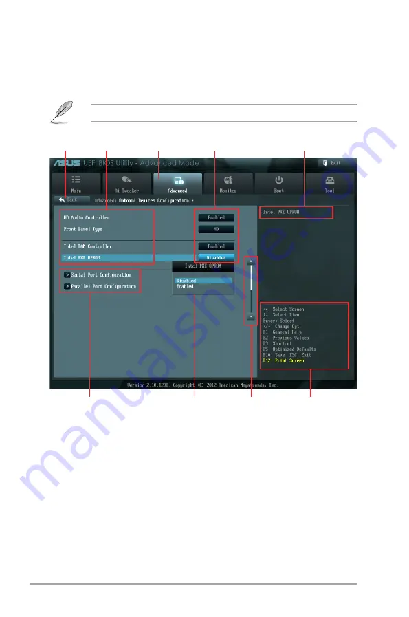
Advanced Mode

The 

Advanced Mode

 provides advanced options for experienced end-users to configure 

the BIOS settings. The figure below shows an example of the 

Advanced Mode

. Refer to the 

following sections for the detailed configurations.

To access the EZ Mode, click 

Exit

, then select 

ASUS EZ Mode

.

Navigation keys


General help

Menu bar

Submenu items

Configuration fields

Menu items

Scroll bar

Pop-up window

Back button

Menu items

The highlighted item on the menu bar displays the specific items for that menu. For example, 

selecting 

Main

 shows the Main menu items.

The other items (Ai Tweaker, Advanced, Monitor, Boot, Tool, and Exit) on the menu bar have 

their respective menu items.

Back button

This button appears when entering a submenu. Press <Esc> or use the USB mouse to click 

this button to return to the previous menu screen.

Submenu items

A greater than sign (>) before each item on any menu screen means that the item has a 

submenu. To display the submenu, select the item and press <Enter>.

Содержание P8Q77-M2

Страница 1: ...Motherboard P8Q77 M2 ...

Страница 2: ...pective companies and are used only for identification or explanation and to the owners benefit without intent to infringe Offer to Provide Source Code of Certain Software This product contains copyrighted software that is licensed under the General Public License GPL under the Lesser General Public License Version LGPL and or other Free Open Source Software Licenses Such software in this product ...

Страница 3: ... the CPU 1 8 1 4 2 CPU heatsink and fan assembly installation 1 10 1 5 System memory 1 12 1 5 1 Overview 1 12 1 5 2 Memory configurations 1 13 1 5 3 Installing a DIMM 1 16 1 6 Expansion slots 1 17 1 6 1 Installing an expansion card 1 17 1 6 2 Configuring an expansion card 1 17 1 6 3 PCI slots 1 17 1 6 4 PCI Express x4 slot 1 17 1 6 4 PCI Express x16 slot 1 18 1 7 Jumpers 1 18 1 8 Connectors 1 20 1...

Страница 4: ... CPU Power Management 2 13 2 5 Advanced menu 2 15 2 5 1 Trusted Computing 2 15 2 5 2 CPU Configuration 2 16 2 5 3 PCH Configuration 2 17 2 5 4 SATA Configuration 2 18 2 5 5 System Agent Configuration 2 19 2 5 6 Intel TXT LT Configuration 2 19 2 5 8 USB Configuration 2 20 2 5 7 AMT Configuration 2 20 2 5 9 Onboard Devices Configuration 2 21 2 5 10 APM 2 22 2 5 11 Serial Port Console Redirection 2 2...

Страница 5: ...sages Force BIOS 2 30 2 7 7 Setup Mode EZ Mode 2 30 2 7 8 Next boot after AC Power Loss Normal Boot 2 30 2 7 9 CSM Parameters 2 30 2 7 10 Security Boot parameters 2 31 2 7 11 Boot Option Priorities 2 32 2 7 12 Boot Override 2 32 2 8 Tools menu 2 33 2 8 1 ASUS EZ Flash 2 Utility 2 33 2 8 2 ASUS O C Profile 2 33 2 8 3 ASUS SPD Information 2 33 2 9 Exit menu 2 34 Appendices Notices A 1 ASUS contact i...

Страница 6: ...your area If you are not sure about the voltage of the electrical outlet you are using contact your local power company If the power supply is broken do not try to fix it by yourself Contact a qualified service technician or your retailer Operation safety Before installing the motherboard and adding devices on it carefully read all the manuals that came with the package Before using the product en...

Страница 7: ...system settings through the BIOS Setup menus Detailed descriptions of the BIOS parameters are also provided Where to find more information Refer to the following sources for additional information and for product and software updates 1 ASUS websites The ASUS website provides updated information on ASUS hardware and software products Refer to the ASUS contact information 2 Optional documentation Yo...

Страница 8: ...lete a task IMPORTANT Instructions that you MUST follow to complete a task NOTE Tips and additional information to help you complete a task Typography Bold text Indicates a menu or an item to select Italics Used to emphasize a word or a phrase Key Keys enclosed in the less than and greater than sign means that you must press the enclosed key Example Enter means that you must press the Enter or Ret...

Страница 9: ...x16 slot 1 x PCI Express 2 0 x4 slot 2 x PCI slots Intel 3rd generation Core processors support PCIe 3 0 Storage Intel Q77 Express Chipset 4 x Serial ATA 3 0 Gb s connectors blue 2 x Serial ATA 6 0 Gb s connectors gray Supports RAID 0 1 10 5 and AHCI mode Supports Intel Smart Response Technology Intel Rapid Start Technology Intel Smart Connect Technology Supports on Intel Core processor family wit...

Страница 10: ...ssis intrusion connector 1 x System panel connector 1 x 24 pin EATX power connector 1 x 8 pin EATX 12V poweer connector 1 x TPM IC onboard 1 x Clear CMOS jumper 1 x DIS_ME jumper 1 x DRCT header BIOS features 128 Mb Flash ROM UEFI BIOS PnP DMI v2 0 WfM 2 0 ACPI v2 0a Multi language BIOS SM BIOS v2 7 ASUS CrashFree BIOS 3 ASUS EZ Flash 2 F12 Printscreen function F3 Shortcut function and ASUS DRAM S...

Страница 11: ...40 pin module DDR3 DIMM_A1 64bit 240 pin module DDR3 DIMM_A2 64bit 240 pin module SATA3G_2 SATA3G_1 SATA3G_4 SATA3G_3 SATA6G_2 SATA6G_1 AUDIO USB1 4 LAN_USB3_12 LPT DRAM_LED MemOK LGA1155 EATX12V USB3_34 F_PANEL SPEAKER USB56 USB78 USB910 COM1 CHASSIS Intel 82579 ASUS P8Q77 M2 motherboard 2 x Serial ATA 6 0 Gb s cables UserGuide 1 x I O Shield User Guide Support DVD If any of the above items is da...

Страница 12: ...xii ...

Страница 13: ...ts of the latest 3D graphics multimedia and Internet applications PCI Express 3 0 PCI Express 3 0 PCIe 3 0 is the PCI Express bus standard that provides twice the performance and speed of PCIe 2 0 It provides an optimal graphics performance unprecedented data speed and seamless transition with its complete backward compatibility to PCIe 1 0 2 0 devices Intel 3rd generation Core processors support ...

Страница 14: ... interaction GPU Boost GPU Boost accelerates the integrated GPU for extreme graphics performance facilitates flexible frequency adjustments and easily delivers stable system level upgrades for every use MemOK MemOK the remarkable memory rescue tool allows you to simply press a button to patch memory issues ensure memory boot compatibility determine fail safe settings and dramatically improve the s...

Страница 15: ...y is switched off or the power cord is detached from the power supply Failure to do so may cause severe damage to the motherboard peripherals or components ASUS CrashFree BIOS 3 ASUS CrashFree BIOS 3 is an auto recovery tool that allows you to restore a corrupted BIOS file using the bundled support DVD or USB flash disk that contains the latest BIOS file ASUS EZ Flash 2 ASUS EZ Flash 2 is a utilit...

Страница 16: ...u physical injury and damage motherboard components 1 3 1 Placement direction When installing the motherboard ensure that you place it into the chassis in the correct orientation The edge with external ports goes to the rear part of the chassis as indicated in the image below 1 3 2 Screw holes Place six screws into the holes indicated by circles to secure the motherboard to the chassis Do not over...

Страница 17: ...RCT 22 6cm 8 9in 24 4cm 9 6in Intel Q77 DDR3 DIMM_B1 64bit 240 pin module DDR3 DIMM_B2 64bit 240 pin module DDR3 DIMM_A1 64bit 240 pin module DDR3 DIMM_A2 64bit 240 pin module SATA3G_2 SATA3G_1 SATA3G_4 SATA3G_3 SATA6G_2 SATA6G_1 AUDIO USB1 4 LAN_USB3_12 LPT DRAM_LED MemOK LGA1155 EATX12V USB3_34 F_PANEL SPEAKER USB56 USB78 USB910 COM1 CHASSIS Intel 82579 DVI D 1 1 2 3 4 11 13 12 14 15 16 17 18 19...

Страница 18: ...ors 7 pin SATA6G_1 2 1 25 9 Clear RTC RAM 3 pin CLRTC 1 19 10 Serial ATA 3 0Gb s connectors 7 pin SATA3G_1 2 3 4 1 26 11 System panel connector 10 1 pin F_PANEL 1 24 12 Speaker connector 4 pin SPEAKER 1 24 13 USB 2 0 connectors 10 1 pin USB56 USB78 USB910 1 27 14 Direct connector 2 pin DRCT 1 22 15 Intel ME jumper 3 pin DIS_ME 1 18 16 Chassis intrusion connector 4 1 pin CHASSIS 1 23 17 LPT connect...

Страница 19: ... immediately if the PnP cap is missing or if you see any damage to the PnP cap socket contacts motherboard components ASUS will shoulder the cost of repair only if the damage is shipment transit related Keep the cap after installing the motherboard ASUS will process Return Merchandise Authorization RMA requests only if the motherboard comes with the cap on the LGA1155 socket The product warranty d...

Страница 20: ...1 8 Chapter 1 Product introduction 1 4 1 Installing the CPU 1 The LGA1156 CPU is incompatible with the LGA1155 socket DO NOT install an LGA1156 CPU on the LGA1155 socket A B 2 3 4 ...

Страница 21: ...ASUS P8Q77 M2 1 9 B A C 5 6 7 ...

Страница 22: ...tion 1 4 2 CPU heatsink and fan assembly installation Apply the Thermal Interface Material to the CPU heatsink and CPU before you install the heatsink and fan if necessary To install the CPU heatsink and fan assembly 1 2 3 4 B B A A ...

Страница 23: ...ASUS P8Q77 M2 1 11 To uninstall the CPU heatsink and fan assembly 2 1 A A B B ...

Страница 24: ...ysical dimensions as a DDR2 DIMM but is notched differently to prevent installation on a DDR2 DIMM socket DDR3 modules are developed for better performance with less power consumption The figure illustrates the location of the DDR3 DIMM sockets Channel Sockets Channel A DIMM_A1 and DIMM_A2 Channel B DIMM_B1 and DIMM_B2 P8Q77 M2 P8Q77 M2 240 pin DDR3 DIMM sockets DIMM_A1 DIMM_A2 DIMM_B1 DIMM_B2 ...

Страница 25: ...ory we recommend that you do any of the following Use a maximum of 3GB system memory if you are using a 32 bit Windows OS Install a 64 bit Windows OS when you want to install 4GB or more on the motherboard This motherboard does not support DIMMs made up of 512Mb 64MB chips or less The default memory operation frequency is dependent on its Serial Presence Detect SPD which is the standard way of acc...

Страница 26: ... 78 AAGD5 9KD XMP 6GB 3 x 2GB DS 9 9 9 27 1 65V CORSAIR CMZ4GX3M2A2000C10 XMP 4GB 2 x 2GB SS 10 10 10 27 1 50V DDR3 1866 O C MHz capability Vendors Part No Size SS DS Chip Brand Chip NO Timing Voltage DIMM socket support Optional 2 DIMMs 4 DIMMs G SKILL F3 14900CL9Q 8GBXL XMP 8GB 2GB x 4 DS 9 9 9 24 1 6V KINGSTON KHX1866C9D3K2 8GX XMP 8GB 4GB X 2 DS 1 65V DDR3 1600 MHz capability Vendors Part No S...

Страница 27: ...5CB256M8GN CG SAMSUNG M378B5273CH0 CH9 4GB DS SAMSUNG K4B2G0846C Super Talent W1333UB4GS 4GB DS SAMSUNG K4B2G0846C Vendors Part No Size SS DS Chip Brand Chip NO Timing Voltage DIMM socket support Optional 2 DIMMs 4 DIMMs Crucial CT12864BA1067 8FF 1GB SS Micron 9GF22D9KPT 7 ELPIDA EBJ21UE8EDF0 AE F 2GB DS ELPIDA J1108EDSE DJ F 1 35V low voltage KINGSTON KVR1066D3N7 1G low profile 1GB SS ELPIDA J110...

Страница 28: ...1 16 Chapter 1 Product introduction 1 5 3 Installing a DIMM 1 2 3 To remove a DIMM B A ...

Страница 29: ...rd is completely seated on the slot 5 Secure the card to the chassis with the screw you removed earlier 6 Replace the system cover 1 6 2 Configuring an expansion card After installing the expansion card configure it by adjusting the software settings 1 Turn on the system and change the necessary BIOS settings if any See Chapter 2 for information on BIOS setup 2 Assign an IRQ to the card 3 Install ...

Страница 30: ... jumper 3 pin DIS_ME This jumper allows you to enable or disable the Intel ME function Set this jumper to pins 1 2 to enable default the Intel ME function and to pins 2 3 to disable it Disable the Intel ME function only when you want to update it 2 2 3 Normal Default Disable ME DIS_ME 1 P8Q77 M2 P8Q77 M2 Intel ME jumper 1 7 Jumpers IRQ assignments for this motherboard A B C D E F G H Intel PCH SAT...

Страница 31: ...lug the power cord and turn ON the computer 4 Hold down the Del key during the boot process and enter BIOS setup to re enter data Except when clearing the RTC RAM never remove the cap on CLRTC jumper default position Removing the cap will cause system boot failure If the steps above do not help remove the onboard battery and move the jumper again to clear the CMOS RTC RAM data After clearing the C...

Страница 32: ...This port connects to a microphone Refer to the audio configuration table below for the function of the audio ports in 2 4 6 or 8 channel configuration Activity Link LED Speed LED Status Description Status Description OFF No link OFF 10Mbps connection ORANGE Linked ORANGE 100Mbps connection BLINKING Data activity GREEN 1Gbps connection Audio 2 4 6 or 8 channel configuration Port Headset 2 channel ...

Страница 33: ...t compatible with DVI I 10 PS 2 Keyboard port This port is for a PS 2 keyboard 1 8 2 Internal connectors 1 Front panel audio connector 10 1 pin AAFP This connector is for a chassis mounted front panel audio I O module that supports either HD Audio or legacy AC 97 audio standard Connect one end of the front panel audio I O module cable to this connector We recommend that you connect a high definiti...

Страница 34: ...r connectors 24 pin EATXPWR 8 pin EATX12V These connectors are for ATX power supply plugs The power supply plugs are designed to fit these connectors in only one orientation Find the proper orientation and push down firmly until the connectors completely fit P8Q77 M2 P8Q77 M2 ATX power connectors EATXPWR PIN 1 PIN 1 GND 5 Volts 5 Volts 5 Volts 5 Volts GND GND GND PSON GND 12 Volts 3 Volts 3 Volts ...

Страница 35: ...nector 4 1 pin CHASSIS This connector is for a chassis mounted intrusion detection sensor or switch Connect one end of the chassis intrusion sensor or switch cable to this connector The chassis intrusion sensor or switch sends a high level signal to this connector when a chassis component is removed or replaced The signal is then generated as a chassis intrusion event By default the pin labeled Ch...

Страница 36: ...ble to this connector The IDE LED lights up or flashes when data is read from or written to the HDD ATX power button soft off button 2 pin PWRBTN This 2 pin connector is for the system power button Reset button 2 pin RESET This 2 pin connector is for the chassis mounted reset button for system reboot without turning off the system power 7 Speaker connector 4 pin SPEAKER The 4 pin connector is for ...

Страница 37: ...on before using Serial ATA hard disk drives The Serial ATA RAID feature RAID 0 1 5 and 10 is available only if you are using Windows XP SP3 or later version When using hot plug and NCQ set the SATA Mode Selection item in the BIOS to AHCI See section 2 5 4 SATA Configuration for details 9 Serial port connector 10 1 pin COM1 This connector is for a serial COM port Connect the serial port module cabl...

Страница 38: ...TA3G_1 4 blue These connectors connect to Serial ATA 3 0 Gb s hard disk drives and optical drives via Serial ATA 3 0 Gb s signal cables If you installed Serial ATA hard disk drives you can create a RAID 0 1 5 and 0 1 10 configurations with the Intel Matrix Storage Technology through the onboard Intel Q77 chipset 11 LPT connector 26 1 pin LPT The LPT Line Printing Terminal connector supports device...

Страница 39: ... This connector is for the additional USB 3 0 ports Connect the USB 3 0 bracket cable to this connector then install the USB 3 0 bracket to the rear side of the chassis If your chassis support customized front panel installation with ASUS USB 3 0 header you can have a front panel USB 3 0 solution The USB 3 0 module is purchased separately Due to Intel limitations the USB3_34 only supports Windows ...

Страница 40: ...ement the system automatically reboots when each timing set is tested If the installed DIMMs still fail to boot after the whole tuning process the DRAM_LED lights continuously Replace the DIMMs with ones recommended in the Memory QVL Qualified Vendors Lists in this user manual or on the ASUS website at www asus com If you turn off the computer and replace DIMMs during the tuning process the system...

Страница 41: ... plugging in any motherboard component The illustration below shows the location of the onboard LED 2 DRAM LED DRAM LED checks the DRAM in sequence during motherboard booting process If an error is found the LED next to the error device will continue lighting until the problem is solved This user friendly design provides an intuitional way to locate the root problem within a second SB_PWR ON Stand...

Страница 42: ...ackage contains the drivers software applications and utilities that you can install to avail all motherboard features If Autorun is NOT enabled in your computer browse the contents of the Support DVD to locate the file ASSETUP EXE from the BIN folder Double click the ASSETUP EXE to run the DVD The following screen is for reference only The contents of the Support DVD are subject to change at any ...

Страница 43: ...8 0 firmware load CPU and chipset requirements Intel Core i3 with B75 Express Chipset Intel Core i5 with B75 Express Chipset Intel Core i7 with B75 Express Chipset Intel Core i5 vPro with one of these chipsets B75 Q77 Intel Core i7 vPro with one of these chipsets B75 Q77 The Intel Management Engine software kit must be installed The Local Manageability Service and the Intel Management Engine Inter...

Страница 44: ...1 32 Chapter 1 Product introduction ...

Страница 45: ...rt DVD that comes with the motherboard package Installing ASUS Update To install ASUS Update 1 Place the support DVD in the optical drive The Specials menu appears 2 Click the Utilities tab then click AI Suite II 3 Follow the onscreen instructions to complete the installation Quit all Windows applications before you update the BIOS using this utility Updating the BIOS To update the BIOS 1 From the...

Страница 46: ...ed utility Before you start using this utility download the latest BIOS file from the ASUS website at www asus com To update the BIOS using EZ Flash 2 1 Insert the USB flash disk that contains the latest BIOS file to the USB port 2 Enter the Advanced Mode of the BIOS setup program Go to the Tool menu to select ASUS EZ Flash 2 Utility and press Enter to enable it 3 Press Tab to switch to the Drive ...

Страница 47: ...atest version Download the latest BIOS file from the ASUS website at www asus com Recovering the BIOS To recover the BIOS 1 Turn on the system 2 Insert the support DVD to the optical drive or the USB flash drive that contains the BIOS file to the USB port 3 The utility automatically checks the devices for the BIOS file When found the utility reads the BIOS file and enters ASUS EZ Flash 2 utility a...

Страница 48: ...ocess The succeeding utility screens are for reference only The actual utility screen displays may not be same as shown Before updating BIOS 1 Prepare the motherboard support DVD and a USB flash drive in FAT32 16 format and single partition 2 Download the latest BIOS file and BIOS Updater from the ASUS website at http support asus com and save them on the USB flash drive NTFS is not supported unde...

Страница 49: ...d keys to select the BIOS file and press Enter BIOS Updater checks the selected BIOS file and prompts you to confirm BIOS update Are you sure to update BIOS Yes No 4 Select Yes and press Enter When BIOS update is done press ESC to exit BIOS Updater Restart your computer DO NOT shut down or reset the system while updating the BIOS to prevent system boot failure For BIOS Updater version 1 30 or late...

Страница 50: ... to boot after changing any BIOS setting try to clear the CMOS and reset the motherboard to the default value See section 1 7 Jumpers for information on how to erase the RTC RAM 2 2 BIOS setup program Use the BIOS Setup program to update the BIOS or configure its parameters The BIOS screens include navigation keys and brief online help to guide you in using the BIOS Setup program Entering BIOS Set...

Страница 51: ...enu for details The boot device options vary depending on the devices you installed to the system The Boot Menu F8 button is available only when the boot device is installed to the system Exits the BIOS setup program without saving the changes saves the changes and resets the system or enters the Advanced Mode Selects the display language of the BIOS setup program Displays the CPU motherboard temp...

Страница 52: ...Scroll bar Pop up window Back button Menu items The highlighted item on the menu bar displays the specific items for that menu For example selecting Main shows the Main menu items The other items Ai Tweaker Advanced Monitor Boot Tool and Exit on the menu bar have their respective menu items Back button This button appears when entering a submenu Press Esc or use the USB mouse to click this button ...

Страница 53: ... corner of the menu screen are the navigation keys for the BIOS setup program Use the navigation keys to select items in the menu and change the settings General help At the top right corner of the menu screen is a brief description of the selected item Configuration fields These fields show the values for the menu items If an item is user configurable you can change the value of the field opposit...

Страница 54: ...rity settings If you have forgotten your BIOS password erase the CMOS Real Time Clock RTC RAM to clear the BIOS password See section 1 7 Jumpers for information on how to erase the RTC RAM The Administrator or User Password items on top of the screen show the default Not Installed After you set a password these items show Installed 2 3 Main menu The Main menu screen appears when you enter the Adva...

Страница 55: ...Enter when prompted to create confirm the password After you clear the password the Administrator Password item on top of the screen shows Not Installed User Password If you have set a user password you must enter the user password for accessing the system The User Password item on top of the screen shows the default Not Installed After you set a password this item shows Installed To set a user pa...

Страница 56: ... set the CPU bus speed to DRAM speed ratio mode Auto DRAM speed is set to the optimized settings 100 133 The CPU bus speed to DRAM speed ratio is set to 100 133 100 100 The CPU bus speed to DRAM speed ratio is set to 100 100 2 4 2 Memory Frequency Auto Allows you to set the memory operating frequency Configuration options Auto DDR3 800MHz DDR3 1066MHz DDR3 1333MHz DDR3 1400MHz DDR3 1600MHz DDR3 18...

Страница 57: ...ording to your CPU model Enhanced Intel SpeedStep Technology Enabled Allows you to enable or disable the Enhanced Intel SpeedStep Technology EIST Disabled Disables this function Enabled The operating system dynamically adjusts the processor voltage and core frequency which may result in decreased average consumption and decreased average heat production Turbo Mode Enabled Enabled Allows processor ...

Страница 58: ...us current allowed at any given time for CPU cores Use and key to adjust the value at 0 125A increment Secondary Plane Current Limit Auto Maximum instantaneous current allowed at any given time for Internal Graphics cores Use and key to adjust the value at 0 125A increment ...

Страница 59: ...items in this menu allow you to set the TPM Trusted Platform Module feature The following items function only when a TPM module is installed in this motherboard TPM Support Disabled Allows you to enable or disable the TPM support Configuration options Disabled Enabled TPM State Disabled This item appears only when you set the TPM Support item to Enabled and allows you to enable or disable the TPM ...

Страница 60: ...ing one system to virtually function as several systems Disabled Disables this function Hardware Prefetcher Enabled Disabled Disables this function Enabled Allows you to turn on off the Mid Level Cache L2 streamer prefetcher Adjacent Cache Line Prefetch Enabled Disabled Disables this function Enabled Allows a hardware platform to perform adjacent cache line prefetching CPU Power Management Configu...

Страница 61: ...lt State CPU C6 Report Auto Allows you to disable or enable the CPU C6 report to OS Auto Set this item automatically Disabled Disables this function Enabled Enables the C6 report function This item should be enabled in order to enable the Enhanced Halt State Package C State Support Auto We recommend that you set this item to Auto for BIOS to automatically detect the C State mode supported by your ...

Страница 62: ...tel R Rapid Start Technology When the item is set to zero the system automatically checks whether the partition size is enough at S3 entry Key in the desired value using the numeric keypad Intel R Smart Connect Technology ISCT Configuration Disabled Allows you to enable or disable the ISCT configuration Configuration options Enabled Disabled 2 5 4 SATA Configuration While entering Setup the BIOS a...

Страница 63: ...ry Display Auto Allows you to decide which graphics controller to use as the primary boot device Configuration options Auto iGPU PCIE PCI iGPU Memory Auto Allows you to set the iGPU memory size Configuration options Auto 32M 64M 96M 128M 448M 480M 512M 1024M Render Standby Enabled Allows you to enable or disable Render Standby by internal graphics devices Configuration options Disabled Enabled iGP...

Страница 64: ... AMT feature Intel AMT Enabled Allow you to enable or disable the Intel Active Management Technology AMT in the BIOS extension Configuration options Enabled Disabled iAMT H W is always enabled This option just controls the BIOS extension execution If enabled this requires additional firmware in the SPI device Invoke MEBx Disabled Enabled Execute MEBx automatically Disabled Press Ctrl P to invoke M...

Страница 65: ...ature Disabled Disables the function 2 5 9 Onboard Devices Configuration HD Audio Controller Enabled Enabled Enables the High Definition Audio Controller Disabled Disables the controller The following item appears only when you set the HD Audio Controller item to Enabled Front Panel Type HD Allows you to set the front panel audio connector AAFP mode to legacy AC 97 or high definition audio dependi...

Страница 66: ...7 9 10 11 12 Device Mode STD Printer Mode Allows you to select the Printer Port mode Configuration options STD Printer Mode SPP Mode EPP 1 9 and SPP Mode EPP 1 7 and SPP Mode ECP Mode ECP and EPP 1 9 Mode ECP and EPP 1 7 Mode 2 5 10 APM Restore AC Power Loss Power Off Power On The system goes into on state after an AC power loss Power Off The system goes into off state after an AC power loss Last ...

Страница 67: ...Redirection Enabled Enables or disables the console redirection feature When enabled it allows you to maintain a system from a remote location by redirecting keyboard input and text output through the serial port Configuration options Enabled Disabled Console Redirection Settings Allows you to configure how the host computer and the remote computer which the user is using will exchange data Both c...

Страница 68: ...Software Xon Xoff 2 5 12 Network Stack Network Stack Disabled This item allows user to disable or enable the UEFI network stack Configuration options Disabled Enabled Ipv4 PXE Support Enabled This item appears only when you set the Network Stack item to Enabled When this item is disabled the IPV4 PXE boot option will not be created Configuration options Disabled Enabled Ipv6 PXE Support Enabled Th...

Страница 69: ...Chapter 2 BIOS information 2 25 2 6 Monitor menu The Monitor menu displays the system temperature power status and allows you to change the fan settings Scroll down to display the following items ...

Страница 70: ...enable the CPU Q Fan Control feature and allows you to set the appropriate performance level of the CPU fan Standard Sets to Standard to make the CPU fan automatically adjust depending on the CPU temperature Silent Sets to Silent to minimize the fan speed for quiet CPU fan operation Turbo Sets to Turbo to achieve maximum CPU fan speed Manual Sets to Manual to assign detailed fan speed control para...

Страница 71: ...rs The following four items appear only when you set Chassis1 2 Fan Profile to Manual Chassis1 2 Upper Temperature 70 Use the and keys to adjust the upper limit of the CPU temperature The values range from 40ºC to 90ºC Chassis1 2 Fan Max Duty Cycle 100 Use the and keys to adjust the maximum chassis fan duty cycle The values range from 60 to 100 When the chassis temperature reaches the upper limit ...

Страница 72: ...ets the power on state of the NumLock to On Off Sets the power on state of the NumLock to Off 2 7 2 Full Screen Logo Enabled Enabled Enables the full screen logo display feature Disabled Disables the full screen logo display feature Scroll down to display the following items Set this item to Enabled to use the ASUS MyLogo 2 feature ...

Страница 73: ...following three items appear only when you set Fast Boot to Enabled USB Support Partial Initial Disabled All USB devices will not be available until OS bootup for a fastest POST time Full Initial All USB devices will be available during POST This process will extend the POST time Partial Initial For a faster POST time only the USB ports with keyboard and mouse connections will be detected PS2 Devi...

Страница 74: ...e third party ROM messages will be displayed only if the third party manufacturer had set the add on device to do so 2 7 7 Setup Mode EZ Mode Advanced Mode Sets Advanced Mode as the default screen for entering the BIOS setup program EZ Mode Sets EZ Mode as the default screen for entering the BIOS setup program 2 7 8 Next boot after AC Power Loss Normal Boot Normal Boot Returns to normal boot on th...

Страница 75: ...iguration options Enabled Disabled Manage All Factory Keys PK KEK DB DBX Install default Secure Boot Keys Configuration options Yes No Platform Key PK Set PK from File Configuration options Acpi a0341d0 0 PCI 1212 USB 2 0 Get PK to File Configuration options OK Delete the PK Configuration options Yes No Key Exchange Key Database KEK Set KEK from File Configuration options OK Get KEK to File Config...

Страница 76: ...t device priority sequence from the available devices The number of device items that appears on the screen depends on the number of devices installed in the system To select the boot device during system startup press F8 when ASUS Logo appears To access Windows OS in Safe Mode press F8 after POST 2 7 12 Boot Override These items displays the available devices The number of device items that appea...

Страница 77: ... create a profile Key in a profile number from one to eight press Enter and then select Yes Load from Profile Allows you to load the previous BIOS settings saved in the BIOS Flash Key in the profile number that saved your CMOS settings press Enter and then select Yes DO NOT shut down or reset the system while updating the BIOS to prevent the system boot failure We recommend that you update the BIO...

Страница 78: ...t menu to ensure the values you selected are saved When you select this option or if you press F10 a confirmation window appears Select Yes to save changes and exit Discard Changes Exit This option allows you to exit the Setup program without saving your changes When you select this option or if you press Esc a confirmation window appears Select Yes to discard changes and exit ASUS EZ Mode This op...

Страница 79: ... different from that to which the receiver is connected Consult the dealer or an experienced radio TV technician for help The use of shielded cables for connection of the monitor to the graphics card is required to assure compliance with FCC regulations Changes or modifications to this unit not expressly approved by the party responsible for compliance could void the user s authority to operate th...

Страница 80: ...waste This product has been designed to enable proper reuse of parts and recycling This symbol of the crossed out wheeled bin indicates that the product electrical and electronic equipment should not be placed in municipal waste Check local regulations for disposal of electronic products DO NOT throw the mercury containing button cell battery in municipal waste This symbol of the crossed out wheel...

Страница 81: ...e Way Fremont CA 94539 USA Telephone 1 812 282 3777 Fax 1 510 608 4555 Web site usa asus com Technical Support Telephone 1 812 282 2787 Support fax 1 812 284 0883 Online support support asus com ASUS COMPUTER GmbH Germany and Austria Address Harkort Str 21 23 D 40880 Ratingen Germany Fax 49 2102 959911 Web site www asus de Online contact www asus de sales Technical Support Telephone 49 1805 010923...

Страница 82: ... name Motherboard Model name P8Q77 M2 conform with the essential requirements of the following directives 2004 108 EC EMC Directive EN 55022 2010 EN 61000 3 2 2006 EN 55013 2001 A1 2003 A2 2006 EN 55024 2010 EN 61000 3 3 2008 EN 55020 2007 A11 2011 1999 5 EC R TTE Directive EN 300 328 V1 7 1 2006 10 EN 300 440 1 V1 6 1 2010 08 EN 300 440 2 V1 4 1 2010 08 EN 301 511 V9 0 2 2003 03 EN 301 908 1 V4 2...

Отзывы: