background image

ASUS 

P5Q3 Deluxe/WiFi-AP@n

2-25

2.8.2 

Internal connectors

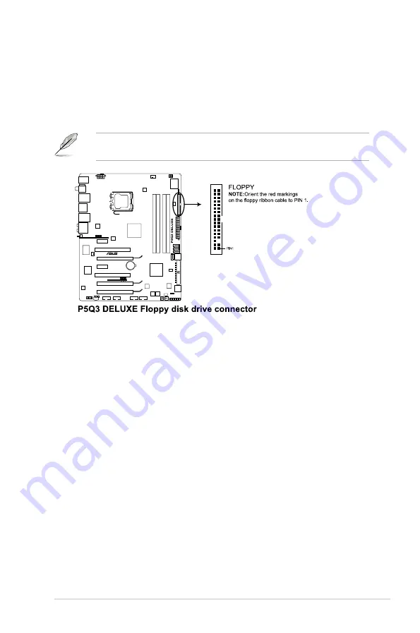
1.  Floppy disk drive connector (34-1 pin FLOPPY)

This connector is for the provided floppy disk drive (FDD) signal cable. Insert 

one end of the cable to this connector, then connect the other end to the 

signal connector at the back of the floppy disk drive.

Pin 5 on the connector is removed to prevent incorrect cable connection when 

using a FDD cable with a covered Pin 5.

Содержание P5Q3 Deluxe WiFi-AP n

Страница 1: ...Motherboard P5Q3 Deluxe WiFi AP n ...

Страница 2: ...CHANTABILITY OR FITNESS FOR A PARTICULAR PURPOSE IN NO EVENT SHALL ASUS ITS DIRECTORS OFFICERS EMPLOYEES OR AGENTS BE LIABLE FOR ANY INDIRECT SPECIAL INCIDENTAL OR CONSEQUENTIAL DAMAGES INCLUDING DAMAGES FOR LOSS OF PROFITS LOSS OF BUSINESS LOSS OF USE OR DATA INTERRUPTION OF BUSINESS AND THE LIKE EVEN IF ASUS HAS BEEN ADVISED OF THE POSSIBILITY OF SUCH DAMAGES ARISING FROM ANY DEFECT OR ERROR IN ...

Страница 3: ...eed 2 1 2 2 Motherboard overview 2 2 2 2 1 Motherboard layout 2 2 2 2 2 Layout contents 2 3 2 2 3 Placement direction 2 4 2 2 4 Screw holes 2 4 2 3 Central Processing Unit CPU 2 5 2 3 1 Installing the CPU 2 6 2 3 2 Installing the CPU heatsink and fan 2 9 2 3 3 Uninstalling the CPU heatsink and fan 2 10 2 3 4 Installing the optional fans 2 11 2 4 System memory 2 12 2 4 1 Overview 2 12 2 4 2 Memory ...

Страница 4: ...PCI Express x16 slot 2 17 2 6 Jumpers 2 19 2 7 Onboard switches 2 21 2 8 Connectors 2 22 2 8 1 Rear panel connectors 2 22 2 8 2 Internal connectors 2 25 2 9 Starting up for the first time 2 38 2 10 Turning off the computer 2 39 2 10 1 Using the OS shut down function 2 39 2 10 2 Using the dual function power switch 2 39 ...

Страница 5: ...use harmful interference to radio or television reception which can be determined by turning the equipment off and on the user is encouraged to try to correct the interference by one or more of the following measures Reorient or relocate the receiving antenna Increase the separation between the equipment and receiver Connect the equipment to an outlet on a circuit different from that to which the ...

Страница 6: ...the power supply is broken do not try to fix it by yourself Contact a qualified service technician or your retailer Operation safety Before installing the motherboard and adding devices on it carefully read all the manuals that came with the package Before using the product make sure all cables are correctly connected and the power cables are not damaged If you detect any damage contact your deale...

Страница 7: ...u have to perform when installing system components It includes description of the switches jumpers and connectors on the motherboard Where to find more information Refer to the following sources for additional information and for product and software updates 1 ASUS websites The ASUS website provides updated information on ASUS hardware and software products Refer to the ASUS contact information 2...

Страница 8: ...y2 Key3 If you must press two or more keys simultaneously the key names are linked with a plus sign Example Ctrl Alt D Command Means that you must type the command exactly as shown then supply the required item or value enclosed in brackets Example At the DOS prompt type the command line afudos i filename afudos iP5Q3DLX ROM DANGER WARNING Information to prevent injury to yourself when trying to c...

Страница 9: ...Express x16 slot at max x4 speed black 2 x PCI Express x1 slots 2 x PCI slots PCIe 2 0 x16_2 slot black at max x8 link If any other PCI Express x1 slot is occupied this slot will downgrade to max x1 speed Storage Intel ICH10R Southbridge 6 x SATA 3 0 Gb s ports Intel Matrix Storage supporting SATA RAID 0 1 5 and 10 Marvell 88SE6121 controller 1 x Ultra DMA 133 100 66 for up to 2 PATA devices 1 x E...

Страница 10: ...aving Solution ASUS EPU Six Engine ASUS 16 Phase Power Design ASUS AI Nap AI Lifestyle Features ASUS Express Gate SSD ASUS WiFi AP n ASUS AI Direct Link ASUS Quiet Thermal Solution ASUS Fanless Design Heat pipe solution ASUS Fanless Design Stack Cool 2 ASUS Fan Xpert ASUS Optional Fan for Water cooling or Passive Cooling only ASUS Crystal Sound AI Audio 2 ASUS Noise Filtering ASUS EZ DIY ASUS Driv...

Страница 11: ... Parameter Recall Back Panel I O Ports 1 x PS 2 Keyboard Mouse combo port 1 x S PDIF Out Coaxial Optical 1 x External SATA 1 x IEEE1394a 2 x RJ45 ports 6 x USB 2 0 1 1 2 x WiFi AP n antenna jacks 8 channel Audio I O Internal I O Connectors 2 x USB connectors support additional 4 USB ports 1 x Floppy disk drive connector 1 x COM connector 1 x IDE connector 6 x SATA connectors red 2 x Drive Xpert SA...

Страница 12: ...ge without notice Support DVD Contents Drivers ASUS PC Probe II ASUS Update ASUS AI Suite Image Editing Suite Anti virus software OEM version Form Factor ATX Form Factor 12 x 9 6 30 5cm x 24 4cm P5Q3 Deluxe WiFi AP n specifications summary ...

Страница 13: ...1 Chapter 1 Product introduction This chapter describes the motherboard features and the new technologies it supports ...

Страница 14: ...ASUS P5Q3 Deluxe WiFi AP n Chapter summary 1 1 1 Welcome 1 1 1 2 Package contents 1 1 1 3 Special features 1 2 ...

Страница 15: ...iler 1 2 Package contents Check your motherboard package for the following items Motherboard ASUS P5Q3 Deluxe WiFi AP n I O modules 1 x Multi function module 1 port IEEE 1394a and 2 port USB 2 0 module Cables 1 x Serial ATA power cable for 2 devices 6 x Serial ATA signal cables 1 x Ultra DMA 133 100 66 cable 1 x Floppy disk drive cable Accessories ASUS Q Shield I O shield 1 x ASUS Optional Fans fo...

Страница 16: ...cess Intel P45 Chipset The Intel P45 Express Chipset is the latest chipset designed to support 16GB of dual channel DDR3 1600 1333 1066 800 architecture 1600 1333 1066 800 FSB Front Side Bus PCIe 2 0 and multi core CPUs It especially includes Intel Fast Memory Access technology that significantly optimizes the use of available memory bandwidth and reduces the latency of the memory accesses DDR3 me...

Страница 17: ...torage peripherals other PC portable devices See pages 2 22 and 2 29 for details S PDIF digital sound ready This motherboard provides convenient connectivity to external home theater audio systems via coaxial and optical S PDIF out SONY PHILIPS Digital Interface jacks It allows to transfer digital audio without converting to analog format and keeps the best signal quality See pages 2 22 and 2 35 f...

Страница 18: ... not suffer from signal loss like before You can also enjoy the choice to set the device in AP Mode or Client Mode Refer to the bundled ASUS WiFi AP n manual for more details AI Direct Link AI Direct Link can easily and efficiently transfer large amounts of data via the network cable saving up to 70 of the total time taken With AI Direct Link it becomes easy to backup or share large data files lik...

Страница 19: ...stable and enhances the overclocking capability Fanless Design Stack Cool 2 ASUS Stack Cool 2 is a fan less and zero noise cooling solution that lowers the temperature of critical heat generating components The motherboard uses a special design on the printed circuit board PCB to dissipate heat these critical components generate Fanless Design Pure Copper Heat pipe The Heat Pipe design effectively...

Страница 20: ...es a virtual center channel that expands the overall sound field without introducing a picket fencing effect Preserving the dialogue or solo performances with downmixing from multichannels will allow you to experience true to life high quality audio Noise Filter This feature detects repetitive and stationary noises non voice signals like computer fans air conditioners and other background noises t...

Страница 21: ... conveniently store or load multiple BIOS settings The BIOS settings can be stored in the CMOS or a separate file giving users freedom to share and distribute their favorite settings ASUS DieHard BIOS The AUS DieHard BIOS consists of two BIOS chips a main BIOS and a backup BIOS The ASUS DieHard BIOS can restore corrupted main BIOS data from the backup BIOS automatically The technology saves users ...

Страница 22: ...eaker 2 Allows the user to adjust the NB Voltage FSB termination Voltage CPU PLL Voltage and the DRAM Voltage in 0 02v steps to finetune voltages to achieve the most precise setting for the ultimate customized overclocking configuration C P R CPU Parameter Recall The C P R feature of the motherboard BIOS allows automatic re setting to the BIOS default settings in case the system hangs due to overc...

Страница 23: ...ter 1 Hardware information This chapter lists the hardware setup procedures that you have to perform when installing system components It includes description of the jumpers and connectors on the motherboard ...

Страница 24: ...proceed 2 1 2 2 Motherboard overview 2 2 2 3 Central Processing Unit CPU 2 5 2 4 System memory 2 12 2 5 Expansion slots 2 15 2 6 Jumpers 2 19 2 7 Onboard switches 2 21 2 8 Connectors 2 22 2 9 Starting up for the first time 2 38 2 10 Turning off the computer 2 39 ...

Страница 25: ... such as the power supply case before handling components to avoid damaging them due to static electricity Hold components by the edges to avoid touching the ICs on them Whenever you uninstall any component place it on a grounded antistatic pad or in the bag that came with the component Before you install or remove any component ensure that the ATX power supply is switched off or the power cord is...

Страница 26: ...2 Chapter 2 Hardware information 2 2 Motherboard overview 2 2 1 Motherboard layout Refer to 2 8 Connectors for more information about rear panel connectors and internal connectors ...

Страница 27: ... pin FLOPPY 2 25 8 ICH10R Serial ATA connectors red 7 pin SATA1 6 2 27 9 IDE connector 40 1 pin PRI_IDE 2 26 10 SIL5723 Serial ATA connectors 7 pin SATA_E1 2 2 28 11 Clear RTC RAM 3 pin CLRTC 2 19 12 System panel connector 20 8 pin PANEL 2 36 13 Onboard switches Power on switch Reset switch 2 21 14 USB connectors 10 1 pin USB 78 USB 910 2 29 15 Serial port connector 10 1 pin COM1 2 35 16 IEEE 1394...

Страница 28: ... motherboard make sure that you place it into the chassis in the correct orientation The edge with external ports goes to the rear part of the chassis as indicated in the image below 2 2 4 Screw holes Place nine 9 screws into the holes indicated by circles to secure the motherboard to the chassis Place this side towards the rear of the chassis ...

Страница 29: ...ASUS will shoulder the cost of repair only if the damage is shipment transit related Keep the cap after installing the motherboard ASUS will process Return Merchandise Authorization RMA requests only if the motherboard comes with the cap on the LGA775 socket The product warranty does not cover damage to the socket contacts resulting from incorrect CPU installation removal or misplacement loss inco...

Страница 30: ... to the socket pins do not remove the PnP cap unless you are installing a CPU 2 Press the load lever with your thumb A then move it to the left B until it is released from the retention tab 3 Lift the load lever in the direction of the arrow to a 135º angle A B Load lever Retention tab 4 Lift the load plate with your thumb and forefinger to a 100º angle 4A then push the PnP cap from the load plate...

Страница 31: ...PU notch Gold triangle mark Alignment key CPU notch 6 Apply several drops of thermal paste to the exposed area of the CPU that the heatsink will be in contact with ensuring that it is spread in an even thin layer The Thermal Interface Material is toxic and inedible If it gets into your eyes or touches your skin ensure to wash it off immediately and seek professional medical help Some heatsinks com...

Страница 32: ... with the Intel Enhanced Memory 64 Technology EM64T Enhanced Intel SpeedStep Technology EIST and Hyper Threading Technology Refer to the Appendix for more information on these CPU features 7 Close the load plate A then push the load lever B until it snaps into the retention tab A B ...

Страница 33: ...ed Thermal Interface Material to the CPU heatsink or CPU before you install the heatsink and fan assembly Make sure that you have installed the motherboard to the chassis before you install the CPU fan and heatsink assembly Orient the heatsink and fan assembly such that the CPU fan cable is closest to the CPU fan connector To install the CPU heatsink and fan 1 Place the heatsink on top of the inst...

Страница 34: ...plug this connector 2 3 3 Uninstalling the CPU heatsink and fan To uninstall the CPU heatsink and fan 1 Disconnect the CPU fan cable from the connector on the motherboard 2 Rotate each fastener counterclockwise 3 Pull up two fasteners at a time in a diagonal sequence to disengage the heatsink and fan assembly from the motherboard A A B B A A B B 4 Carefully remove the heatsink and fan assembly fro...

Страница 35: ...lize the system 1 Position the fan above the pipe and heatsink assembly 2 Fit the fan to the grooved edge of the heatsink 3 Carefully push down the fan until it snugly fits the heatsink then connect the fan cable 4 The photo shows the fan installed on the motherboard Plug the optional fan cable to the CHA_FAN1 2 connector on the motherboard Make sure the optional fan is installed correctly to prev...

Страница 36: ... sockets A DDR3 module has the same physical dimensions as a DDR2 DIMM but is notched differently to prevent installation on a DDR2 DIMM socket DDR3 modules are developed for better performance with less power consumption The figure illustrates the location of the DDR3 DIMM sockets Channel Sockets Channel A DIMM_A1 and DIMM_A2 Channel B DIMM_B1 and DIMM_B2 ...

Страница 37: ...less than 3GB because the address space is reserved for other critical functions This limitation appears on Windows XP Vista 32 bit operation system which does not support Physical Address Extension PAE If you install Windows XP Vista 32 bit operation system a total memory of less than 3GB is recommended This motherboard does not support memory modules made up of 128 Mb chips Due to chipset limita...

Страница 38: ... retaining clips snap back in place and the DIMM is properly seated Make sure to unplug the power supply before adding or removing DIMMs or other system components Failure to do so may cause severe damage to both the motherboard and the components A DIMM is keyed with a notch so that it fits in only one direction DO NOT force a DIMM into a socket to avoid damaging the DIMM 3 Unlocked retaining cli...

Страница 39: ...cure the card to the chassis with the screw you removed earlier 6 Replace the system cover 2 5 2 Configuring an expansion card After installing the expansion card configure it by adjusting the software settings 1 Turn on the system and change the necessary BIOS settings if any See Chapter 3 for information on BIOS setup 2 Assign an IRQ to the card Refer to the tables on the next page 3 Install the...

Страница 40: ... 5 IRQ Holder for PCI Steering 11 6 IRQ Holder for PCI Steering 12 7 Reserved 13 8 Numeric Data Processor 14 9 Primary IDE Channel IRQ assignments for this motherboard A B C D E F G H PCIE1_1 shared PCIE1_2 shared PCIE16_1 shared PCIE16_2 shared PCIE16_3 shared LAN 8056 shared LAN 8001 shared Marvell 6121 shared PCI_1 shared PCI_2 shared USB controller 1 shared USB controller 2 shared USB controll...

Страница 41: ...on of the slot 2 5 6 PCI Express 2 0 x16 slots This motherboard has two PCI Express 2 0 x16 slots that support PCI Express x16 2 0 graphic cards complying with the PCI Express specifications Refer to the figure below for the location of the slots 2 5 7 Universal PCI Express x16 slot This motherboard also supports one Universal PCI Express x16 slot with a maximum speed of x4 link Refer to the figur...

Страница 42: ...etter performance Use the two PCIe 2 0 x16 slots and the universal PCIe x16 slot for 3 Way CrossFireX mode We recommend that you provide sufficient power when running CrossFireX mode See page 2 32 for details If one of the PCIe x1 slots is occupied the universal PCI Express x16 slot black will downgrade to max x1 speed Connect a chassis fan to the motherboard connector labeled CHA_FAN1 2 3 when us...

Страница 43: ...hen move the cap back to pins 1 2 4 Reinstall the battery 5 Plug the power cord and turn ON the computer 6 Hold down the Del key during the boot process and enter BIOS setup to re enter data You do not need to clear the RTC when the system hangs due to overclocking For system failure due to overclocking use the C P R CPU Parameter Recall feature Shut down and reboot the system so the BIOS can auto...

Страница 44: ...t the desired CPU and Northbridge performance Make sure your system functions well under the highest BIOS voltage settings before you change the setting of these two jumpers DO NOT set the OV_CPU jumper to pins 1 2 when you install a new CPU and have not booted for the first time Doing so may cause the system to halt For system failure due to the wrong setting of the OV_CPU jumper shut down the co...

Страница 45: ...ne performance when working on a bare or open case system This is ideal for overclockers and gamers who continually change settings to enhance system performance 1 Power on switch Press the power on switch to wake power up the system 2 Reset switch Press the reset switch to reboot the system ...

Страница 46: ... RJ 45 port This Marvell LAN port allows Gigabit connection to a Local Area Network LAN through a network hub Refer to the table below for the LAN port LED indications To compliant with Energy Star 4 0 this port does not support WOL Wake on LAN function Activity Link LED Speed LED Status Description Status Description OFF No link OFF 10 Mbps connection ORANGE Linked ORANGE 100 Mbps connection BLIN...

Страница 47: ...o configure a RAID0 or RAID1 connect an external Serial ATA hard disk drive to the External SATA port Refer to the audio configuration table below for the function of the audio ports in 2 4 6 or 8 channel configuration Audio 2 4 6 or 8 channel configuration Port Headset 2 channel 4 channel 6 channel 8 channel Light Blue Line In Line In Line In Line In Lime Line Out Front Speaker Out Front Speaker ...

Страница 48: ...ure that you have connected the Serial ATA signal cable and installed Serial ATA hard disk drives otherwise you cannot enter the JMicron RAID utility and SATA BIOS setup during POST If you intend to create a RAID configuration using this connector set the J Micron eSATA PATA Controller Mode in the BIOS to RAID When using hot plug and NCQ set the J Micron eSATA PATA Controller Mode in the BIOS to A...

Страница 49: ...nnector is for the provided floppy disk drive FDD signal cable Insert one end of the cable to this connector then connect the other end to the signal connector at the back of the floppy disk drive Pin 5 on the connector is removed to prevent incorrect cable connection when using a FDD cable with a covered Pin 5 ...

Страница 50: ...correct insertion when you connect the IDE cable Use the 80 conductor IDE cable for Ultra DMA 133 100 66 IDE devices If any device jumper is set as Cable Select make sure all other device jumpers have the same setting 2 IDE connector 40 1 pin PRI_E IDE The onboard IDE connector is for the Ultra DMA 133 100 66 signal cable There are three connectors on each Ultra DMA 133 100 66 signal cable blue bl...

Страница 51: ...ctor When using hot plug and NCQ set the Configure SATA as in the BIOS to AHCI 3 ICH10R Serial ATA connectors 7 pin SATA 1 6 red These connectors are for the Serial ATA signal cables for Serial ATA hard disk drives If you installed Serial ATA hard disk drives you can create a RAID 0 1 5 and 10 configuration with the Intel Matrix Storage Technology through the onboard Intel ICH10R RAID controller T...

Страница 52: ...Technology through the onboard Silicon Image SIL5723 controller Before using the Drive Xpert technology make sure that you have connected the SATA signal cables and installed SATA hard disk drives The SATA_E1 and SATA_E2 ports are for SATA hard drives only ATAPI device is not supported Make necessary backup before using the Drive Xpert function All original data of the SATA_E2 hard drive will be e...

Страница 53: ...n speed Never connect a 1394 cable to the USB connectors Doing so will damage the motherboard 6 IEEE 1394a port connector 10 1 pin IE1394_2 This connector is for an IEEE 1394a port Connect the IEEE 1394a module cable to this connector then install the module to a slot opening at the back of the system chassis If your chassis suppots front panel USB ports you can attach a front panel USB cable to t...

Страница 54: ...damage the motherboard components These are not jumpers Do not place jumper caps on the fan connectors Only the CPU FAN and CHA FAN 1 3 connectors support the ASUS Advanced Q Fan feature If you install two VGA cards we recommend that you plug the rear chassis fan cable to the motherboard connector labled CHA_FAN1 or CHA_FAN2 for better themal environment Never connect a USB cable to the IEEE 1394a...

Страница 55: ...you intend to use the chassis intrusion detection feature 9 Front panel audio connector 10 1 pin AAFP This connector is for a chassis mounted front panel audio I O module that supports either HD Audio or legacy AC 97 audio standard Connect one end of the front panel audio I O module cable to this connector We recommend that you connect a high definition front panel audio module to this connector t...

Страница 56: ...wer output is recommended when configuring a system with more power consuming devices The system may become unstable or may not boot up if the power is inadequate If you are uncertain about the minimum power supply requirement for your system refer to the Recommended Power Supply Wattage Calculator at http support asus com PowerSupplyCalculator PSCalculator aspx SLanguage en us for details If you ...

Страница 57: ...HDD IDE CDROM IDE HDD USB Total PSU Voltage V 6 1 1 1 4 Po_max w Current A 10 45 10 45 10 12 68 2 5 708 577 Power W 62 7 10 45 10 12 68 10 Normal Loading CPU KSF 3 0XE Memory 1 GB 4 VGA 8800 Ultra 2 SATA HDD 4 eSATA HDD 1 IDE CDROM 1 IDE HDD 0 USB 4 12V_8Pin 12V_24pin 5V_24pin 3V_24pin 12V_VGA1 12V_VGA2 12V_VGA3 Voltage V 12 14 12 21 5 225 3 455 12 2 12 2 Current A 6 74 8 92 6 22 6 87 6 52 6 82 Po...

Страница 58: ...e V 12 19 12 21 5 22 3 456 12 16 Current A 3 19 5 55 5 04 5 36 6 5 Power W 38 886 67 766 26 309 18 524 79 04 0 0 SATA HDD eSATA HDD IDE CDROM IDE HDD USB Total PSU Voltage V 2 1 1 0 4 Po_max w Current A 10 45 10 45 10 12 68 2 5 281 875 Power W 20 9 10 45 10 0 10 11 Optical drive audio connector 4 pin CD This connector allows you to receive stereo audio input from sound sources such as a CD ROM TV ...

Страница 59: ...ng ASUS HDMI equipped graphics card connect the HDMI card to this connector with a S PDIF out cable The ASUS HDMI equipped graphics card and S PDIF out cable are purchased separately 13 Serial port connector 10 1 pin COM1 This connector is for a serial COM port Connect the serial port module cable to this connector then install the module to a slot opening at the back of the system chassis ...

Страница 60: ...warning speaker 4 pin SPEAKER This 4 pin connector is for the chassis mounted system warning speaker The speaker allows you to hear system beeps and warnings ATX power button soft off button 2 pin PWRSW This connector is for the system power button Pressing the power button turns the system on or puts the system in sleep or soft off mode depending on the BIOS settings Pressing the power switch for...

Страница 61: ...nnect the front panel cables to the ASUS Q Connector Refer to the labels on the Q Connector to know the detailed pin definitions then match them to the respective front panel cable labels 2 Install the ASUS Q Connector to the system panel connector making sure the orientation matches the labels on the motherboard 3 The front panel functions are now enabled The figure shows the Q Connector properly...

Страница 62: ...After applying power the system power LED on the system front panel case lights up For systems with ATX power supplies the system LED lights up when you press the ATX power button If your monitor complies with green standards or if it has a power standby feature the monitor LED may light up or switch between orange and green after the system LED turns on The system then runs the power on self test...

Страница 63: ...Start button then select Turn Off Computer 2 Click the Turn Off button to shut down the computer 3 The power supply should turn off after Windows shuts down 2 10 2 Using the dual function power switch While the system is ON pressing the power switch for less than four seconds puts the system to sleep mode or to soft off mode depending on the BIOS setting Pressing the power switch for more than fou...

Страница 64: ...2 40 Chapter 2 Hardware information ...

Отзывы: