


4-12
Chapter.4:.BIOS.setup
Use [ENTER], [TAB]
or [SHIFT-TAB] to
select a field.
Use [+] or [-] to
configure system time.
Select Screen
Select Item
+- Change Field
Tab Select Field
F1 General Help
F10 Save and Exit
ESC Exit
System Time
[04:51:19]
System Date
[Tue 01/01/2002]
Legacy Diskette A
[1.44M, 3.5 in]
Primary IDE Master
: [Not Detected]
Primary IDE Slave
: [Not Detected]
Third IDE Master
: [Not Detected]
Third IDE Slave
: [Not Detected]
Fourth IDE Master
: [Not Detected]
Fourth IDE Slave
: [Not Detected]
IDE Configuration
System Information
4.2.2.
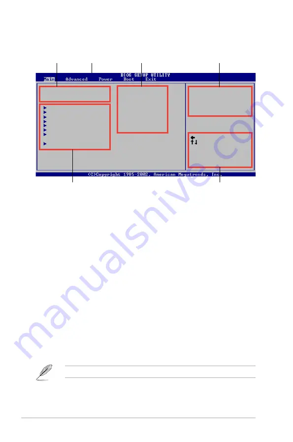
Menu.bar
The menu bar on top of the screen has the following main items:
Main
For changing the basic system configuration
Advanced
For changing the advanced system settings
Power
For changing the advanced power management (APM)
configuration
Boot
For changing the system boot configuration
Exit
For selecting the exit options and loading default
settings
To select an item on the menu bar, press the right or left arrow key on the keyboard
until the desired item is highlighted.
4.2.3.
Navigation.keys
At the bottom right corner of a menu screen are the navigation keys for that
particular menu. Use the navigation keys to select items in the menu and change
the settings.
4.2.1.
BIOS.menu.screen
Some of the navigation keys differ from one screen to another.
Navigation.keys
General.help
Menu.bar
Sub-menu.items
Configuration fields
Menu.items
Содержание P5LD2-X 1333
Страница 1: ...Motherboard P5LD2 X 1333 ...
Страница 12: ...xii ...
Страница 13: ...1 Product introduction This chapter describes the motherboard features and the new technologies it supports ...
Страница 14: ...ASUS P5LD2 X 1333 Chapter summary 1 1 1 Welcome 1 1 1 2 Package contents 1 1 1 3 Special features 1 2 ...
Страница 20: ...1 Chapter 1 Product introduction ...
Страница 54: ...ASUS P5LD2 X 1333 Chapter summary 3 3 1 Starting up for the first time 3 1 3 2 Powering off the computer 3 2 ...
Страница 96: ...4 38 Chapter 4 BIOS setup ...
Страница 107: ...A CPU features The Appendix describes the CPU features that the motherboard supports ...


