background image

2-6

Chapter 2: BIOS information

2.2.3 

Navigation keys

At the bottom right corner of a menu screen are the navigation keys for that particular menu. 

Use the navigation keys to select items in the menu and change the settings.

Some of the navigation keys differ from one screen to another.

2.2.4 

Menu items

The highlighted item on the menu bar displays the specific items for that menu. For example, 

selecting Main shows the Main menu items.

The other items (Advanced, Power, Boot, Tools, and Exit) on the menu bar have their 

respective menu items.

2.2.5 

Submenu items

A solid triangle before each item on any menu screen means that the item has a submenu. To 

display the submenu, select the item and press 

<Enter>

.

2.2.6 

Configuration fields

These fields show the values for the menu items. If an item is user- configurable, you can 

change the value of the field opposite the item. You cannot select an item that is not user-

configurable.A configurable field is enclosed in brackets, and is highlighted when selected. To 

change the value of a field, select it then press <Enter> 

to display a list of options. Refer to 

2.2.7 Pop-up window

.

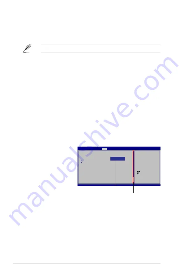
2.2.7 

Pop-up window

Select a menu item then press 

<Enter>

 to display a pop-up 

window with the configuration 

options for that item.

2.2.8 

Scroll bar

A scroll bar appears on the right 

side of a menu screen when there 

are items that do not fit on the 

screen. Press the 

<Up> / <Down>


arrow keys or 

<Page Up> /<Page 

Down>

 keys to display the other 

items on the screen.

2.2.9 

General help

At the top right corner of the menu screen is a brief description of the selected item.

   Select Screen

    Select Item

+-   Change Field

Tab   Select Field

F1   General Help

F10   Save and Exit

ESC   Exit

v02.58 (C)Copyright 1985-2009, American, American Megatrends, Inc.

BIOS SETUP UTILITY

Main      Advanced    Power    Boot    Tools    Exit

Suspend Mode 


[Auto]

ACPI 2.0 Support 


[Disabled] 

ACPI APIC support 


[Enabled] 

 APM Configuration

 Hardware Monitor

Use [ENTER], [TAB] or 

[SHIFT-TAB] to select 

a field.

Use [+] or [-] to 

configure system 

Time.

  Options

Disabled

Enabled

Pop-up window

Scroll bar

Содержание P5KPL-AM EPU

Страница 1: ...Motherboard P5KPL AM EPU ...

Страница 2: ...CHANTABILITY OR FITNESS FOR A PARTICULAR PURPOSE IN NO EVENT SHALL ASUS ITS DIRECTORS OFFICERS EMPLOYEES OR AGENTS BE LIABLE FOR ANY INDIRECT SPECIAL INCIDENTAL OR CONSEQUENTIAL DAMAGES INCLUDING DAMAGES FOR LOSS OF PROFITS LOSS OF BUSINESS LOSS OF USE OR DATA INTERRUPTION OF BUSINESS AND THE LIKE EVEN IF ASUS HAS BEEN ADVISED OF THE POSSIBILITY OF SUCH DAMAGES ARISING FROM ANY DEFECT OR ERROR IN ...

Страница 3: ... 5 1 5 3 Motherboard layout 1 6 1 5 4 Layout contents 1 6 1 6 Central Processing Unit CPU 1 7 1 6 1 Installing the CPU 1 7 1 6 2 Installing the CPU heatsink and fan 1 10 1 6 3 Uninstalling the CPU heatsink and fan 1 11 1 7 System memory 1 12 1 7 1 Overview 1 12 1 7 2 Memory configurations 1 13 1 7 3 Installing a DIMM 1 17 1 7 4 Removing a DIMM 1 17 1 8 Expansion slots 1 18 1 8 1 Installing an expa...

Страница 4: ...2 4 2 2 1 BIOS menu screen 2 5 2 2 2 Menu bar 2 5 2 2 3 Navigation keys 2 6 2 2 4 Menu items 2 6 2 2 5 Submenu items 2 6 2 2 6 Configuration fields 2 6 2 2 7 Pop up window 2 6 2 2 8 Scroll bar 2 6 2 2 9 General help 2 6 2 3 Main menu 2 7 2 3 1 System Time 2 7 2 3 2 System Date 2 7 2 3 3 Primary IDE Master Slave and SATA1 4 2 7 2 3 4 Storage Configuration 2 8 2 3 5 System Information 2 9 2 4 Advanc...

Страница 5: ...PI APIC Support 2 16 2 5 4 APM Configuration 2 16 2 5 5 Hardware Monitor 2 17 2 6 Boot menu 2 17 2 6 1 Boot Device Priority 2 17 2 6 2 Boot Settings Configuration 2 18 2 6 3 Security 2 18 2 7 Tools menu 2 20 2 7 1 ASUS EZ Flash 2 2 20 2 7 2 AI NET 2 2 20 2 8 Exit menu 2 21 Contents ...

Страница 6: ...n between the equipment and receiver Connect the equipment to an outlet on a circuit different from that to which the receiver is connected Consult the dealer or an experienced radio TV technician for help Canadian Department of Communications Statement This digital apparatus does not exceed the Class B limits for radio noise emissions from digital apparatus set out in the Radio Interference Regul...

Страница 7: ...tion safety Before installing the motherboard and adding devices on it carefully read all the manuals that came with the package Before using the product make sure all cables are correctly connected and the power cables are not damaged If you detect any damage contact your dealer immediately To avoid short circuits keep paper clips screws and staples away from connectors slots sockets and circuitr...

Страница 8: ...on to prevent injury to yourself when trying to complete a task CAUTION Information to prevent damage to the components when trying to complete a task NOTE Tips and additional information to help you complete a task IMPORTANT Instructions that you MUST follow to complete a task Typography Bold text Indicates a menu or an item to select Italics Used to emphasize a word or a phrase Key Keys enclosed...

Страница 9: ...ry of 4GB capacity or more Windows 32 bit operating system may only recognize less than 3GB We recommend a maximum of 3GB system memory if you are using a Windows 32 bit OS Expansion slots 1 x PCIe x16 slot 1 x PCIe x1 slot 2 x PCI slots Storage Southbridge Intel ICH7 supports 4 x Serial ATA 3Gb s 1 x UltraDMA 100 66 33 LAN PCIe Gb LAN Graphics Intel Graphics Media Accelerator Intel GMA 3100 inter...

Страница 10: ...nnector 1 x Chassis fan connector 1 x CD audio in connector 1 x IDE connector 1 x 24 pin EATX Power connector 1 x 4 pin ATX 12V Power connector 4 x SATA connectors 1 x Speaker connector BIOS features 8 Mb Flash ROM AMI BIOS PnP DMI v2 0 WfM2 0 SMBIOS v2 5 ACPI v2 0a Manageability WOL PXE RPL WOR by Ring PME Wake Up Accessories 1 x UltraDMA 100 66 33 cable 1 x Serial ATA cable 1 x I O shield User M...

Страница 11: ...tel LGA775 Core 2 Extreme Core 2 Quad Core 2 Duo processors which are excellent for multitasking multimedia and enthusiastic gamers with 1600 O C 1333 1066 800 MHz FSB This motherboard also supports Intel CPUs in the 45nm manufacturing process 1 1 Welcome Thank you for buying an ASUS P5KPL AM EPU motherboard The motherboard delivers a host of new features and latest technologies making it another ...

Страница 12: ... demanding applications Serial ATA 3Gb s technology This motherboard supports hard drives based on the Serial ATA SATA 3Gb s storage specifications delivering enhanced scalability and doubling the bus bandwidth for high speed data saving and retrieval Gigabit LAN solution The onboard LAN controller is a highly integrated Gb LAN controller It is enhanced with an ACPI management function to provide ...

Страница 13: ...OS based utility ASUS AI NET2 ASUS AI NET2 remotely detects the cable connection immediately after turning on the system and any faulty cable connections are reported back up to 100 meters at 1 meter accuracy C P R CPU Parameter Recall The BIOS C P R feature automatically restores the CPU default settings when the system hangs due to overclocking failure C P R eliminates the need to open the syste...

Страница 14: ...hem Whenever you uninstall any component place it on a grounded antistatic pad or in the bag that came with the component Before you install or remove any component ensure that the ATX power supply is switched off or the power cord is detached from the power supply Failure to do so may cause severe damage to the motherboard peripherals or components Onboard LED The motherboard comes with a standby...

Страница 15: ...injury and damage motherboard components 1 5 1 Placement direction When installing the motherboard ensure that you place it into the chassis in the correct orientation The edge with external ports goes to the rear part of the chassis as indicated in the image below 1 5 2 Screw holes Place six screws into the holes indicated by circles to secure the motherboard to the chassis Do not overtighten the...

Страница 16: ...ATA1 4 1 24 3 USB device wake up 3 pin USBPW1 4 USBPW5 8 1 20 11 USB connectors 10 1 pin USB56 USB78 1 27 4 Intel CPU socket 1 7 12 System panel connector 10 1 pin F_PANEL 1 26 5 CPU and chassis fan connectors 4 pin CPU_FAN 3 pin CHA_FAN 1 22 13 Digital audio connector 4 1 pin SPDIF_OUT 1 23 6 DDR2 DIMM sockets 1 12 14 Onboard LED 1 4 7 IDE connector 40 1 pin PRI_IDE 1 25 15 Front panel audio conn...

Страница 17: ...e PnP cap socket contacts motherboard components ASUS will shoulder the cost of repair only if the damage is shipment transit related Keep the cap after installing the motherboard ASUS will process Return Merchandise Authorization RMA requests only if the motherboard comes with the cap on the LGA775 socket The product warranty does not cover damage to the socket contacts resulting from incorrect C...

Страница 18: ...ever Retention tab 4 Lift the load plate with your thumb and forefinger to a 100º angle 4A then push the PnP cap from the load plate window to remove 4B 3 Lift the load lever in the direction of the arrow to a 135º angle PnP cap Load plate 4A 4B 3 5 Position the CPU over the socket ensuring that the gold triangle is on the bottom left corner of the socket then fit the socket alignment key into the...

Страница 19: ... Thermal Interface Material If it gets into your eyes or touches your skin ensure that you wash it off immediately and seek professional medical help Some heatsinks come with pre applied thermal paste If so skip this step To prevent contaminating the paste DO NOT spread the paste with your finger directly 7 Close the load plate A then push the load lever B until it snaps into the retention tab A B...

Страница 20: ...u have properly applied Thermal Interface Material to the CPU heatsink or CPU before you install the heatsink and fan assembly Ensure that you have installed the motherboard to the chassis before you install the CPU fan and heatsink assembly The type of CPU heatsink and fan assembly may differ but the installation steps and functions should remain the same The illustration above is for reference o...

Страница 21: ...rs can occur if you fail to plug this connector 1 6 3 Uninstalling the CPU heatsink and fan To uninstall the CPU heatsink and fan 1 Disconnect the CPU fan cable from the connector on the motherboard 2 Rotate each fastener counterclockwise 3 Pull up two fasteners at a time in a diagonal sequence to disengage the heatsink and fan assembly from the motherboard A A B B A A B B ...

Страница 22: ...ate 2 DDR2 Dual Inline Memory Modules DIMM sockets The figure illustrates the location of the DDR2 DIMM sockets Channel Sockets Channel A DIMM_A1 Channel B DIMM_B1 4 Carefully remove the heatsink and fan assembly from the motherboard 5 Rotate each fastener clockwise to ensure correct orientation when reinstalling ...

Страница 23: ... or more memory on the motherboard This motherboard does not support DIMMs made up of 256 megabits Mb or less This motherboard supports up to 4 GB on Windows XP Professional x64 and Windows Vista x64 editions You may install a maximum of 2GB DIMMs on each slot The default memory operation frequency is dependent on its Serial Presence Detect SPD which is the standard way of accessing information fr...

Страница 24: ...12804QBF25S0054707PEBPA 1G Kingston KVR800D2N5 1G N A Samsung DS K4T51083QC ZCE7 1G Kingston KHX6400D2LL 1G N A Kingston DS Heat Sink Package 1G Kingston KVR800D2N5 1G N A Nanya DS NT5TU64M8BE 25C62321800CP 1G Kingston KHX6400D2LLK2 1GN N A Kingston DS Heat Sink Package 2G Kingston KHX6400D2K2 2G N A Kingston DS Heat Sink Package 512MB Samsung KR M378T6553CZ3 CE7 N A Samsung SS K4T51083QC ZCE7 1G ...

Страница 25: ...SSSS17310 512MB Qimonda HYS64T32000HU 3S A N A Qimonda SS HYB18T5128000AF 3SSSS27416 512MB Qimonda HYS64T64000HU 3S A N A Qimonda SS HYB18T512800AF3SFSS05346 1G Qimonda HYS64T128020HU 3S A N A Qimonda DS HYB18T512800AF3SSSS28104 512MB Corsair VS512MB667D2 N A Corsair SS 64M8CFEGPS0900647 512MB Corsair VS512MB667D2 N A Corsair DS MIII0052532M8CEC 1G Corsair VS1GB667D2 N A Corsair DS MID095D62864M8C...

Страница 26: ...Hynix DS HY5PS12821BFP E3 A 512MB AENEON AET660UD00 30DA98Z N A AENEON SS AET93F30DA 0552 512MB AENEON AET660UD00 30DB97X 5 AENEON SS AET93R300B 0634 1G AENEON AET760UD00 30DA98Z N A AENEON DS AET93F30DA8EE47414G 0540 1G AENEON AET760UD00 30DA98Z N A AENEON DS AET93F30DA 0604 1G AENEON AET760UD00 30DB97X 5 AENEON DS AET93R300B 0639 512MB TAKEMS TMS51B264C081 665QI 5 takeMS SS MS18T51280 3 512MB TA...

Страница 27: ...ng clip 1 DDR2 DIMM notch 2 1 A DDR2 DIMM is keyed with a notch so that it fits in only one direction DO NOT force a DIMM into a socket to avoid damaging the DIMM 3 Firmly insert the DIMM into the socket until the retaining clips snap back in place and the DIMM is properly seated Locked Retaining Clip 3 1 7 4 Removing a DIMM To remove a DIMM 1 Simultaneously press the retaining clips outward to un...

Страница 28: ...the chassis with the screw you removed earlier 6 Replace the system cover 1 8 2 Configuring an expansion card After installing the expansion card configure it by adjusting the software settings 1 Turn on the system and change the necessary BIOS settings if any See Chapter 2 for information on BIOS setup 2 Assign an IRQ to the card 3 Install the software drivers for the expansion card When using PC...

Страница 29: ...learance reinstall the battery You do not need to clear the RTC when the system hangs due to overclocking For system failure due to overclocking use the CPU Parameter Recall C P R feature Shut down and reboot the system then the BIOS automatically resets parameter settings to default values Due to the chipset limitation AC power off is required before you use the C P R function You must turn off a...

Страница 30: ...from S3 and S4 sleep modes no power to CPU DRAM in slow refresh power supply in reduced power mode 3 Keyboard power 3 pin KBPWR This jumper allows you to enable or disable the keyboard wake up feature When you set this jumper to pins 2 3 5VSB you can wake up the computer by pressing a key on the keyboard the default is the Space Bar s This feature requires an ATX power supply that can supply at le...

Страница 31: ...connection BLINKING Data activity GREEN 1 Gbps connection 4 Line In port light blue This port connects the tape CD DVD player or other audio sources 5 Line Out port lime This port connects a headphone or a speaker In 4 channel and 6 channel configurations the function of this port becomes Front Speaker Out 6 Microphone port pink This port connects a microphone Refer to the audio configuration tabl...

Страница 32: ...otal of 1A 2 2A 26 64 W max at 12V Connect the fan cables to the fan connectors on the motherboard ensuring that the black wire of each cable matches the ground pin of the connector 7 USB 2 0 ports 1 and 2 These two 4 pin Universal Serial Bus USB ports are available for connecting USB 2 0 devices 8 USB 2 0 ports 3 and 4 These two 4 pin Universal Serial Bus USB ports are available for connecting US...

Страница 33: ...minimum power of 400 W Do not forget to connect the 4 pin ATX12V power plug Otherwise the system will not boot We recommend that you use a PSU with a higher power output when configuring a system with more power consuming devices or when you intend to install additional devices The system may become unstable or may not boot up if the power is inadequate 3 Digital audio connector 4 1 pin SPDIF_OUT ...

Страница 34: ...or the Serial ATA signal cables for Serial ATA hard disk drives 5 Optical drive audio connector 4 pin CD This connector allows you to receive stereo audio input from sound sources such as a CD ROM TV tuner or MPEG card Install the Windows XP Service Pack 2 or later version before using Serial ATA ...

Страница 35: ...your device Drive jumper setting Mode of device s Cable connector Single device Cable Select or Master Black Two devices Cable Select Master Black Slave Gray Master Master Black or gray Slave Slave Pin 20 on the IDE connector is removed to match the covered hole on the Ultra DMA cable connector This prevents incorrect insertion when you connect the IDE cable Use the 80 conductor IDE cable for Ultr...

Страница 36: ...to this connector The HD LED lights up or flashes when data is read from or written to the HDD Power Soft off button 2 pin PWRBTN This 2 pin connector is for the system power button Pressing the power button turns the system ON or puts the system in SLEEP or SOFT OFF mode depending on the BIOS settings Pressing the power switch for more than four seconds while the system is ON turns the system OFF...

Страница 37: ... pin AAFP This connector is for a chassis mounted front panel audio I O module that supports either HD Audio or legacy AC 97 audio standard Connect one end of the front panel audio I O module cable to this connector We recommend that you connect a high definition front panel audio module to this connector to avail of the motherboard s high definition audio capability If you want to connect a high ...

Страница 38: ...ty 1 11 2 Support DVD information The Support DVD that comes with the motherboard package contains the drivers software applications and utilities that you can install to avail all motherboard features If Autorun is NOT enabled in your computer browse the contents of the Support DVD to locate the file ASSETUP EXE from the BIN folder Double click the ASSETUP EXE to run the DVD The following screen ...

Страница 39: ...e BIOS 1 From the Windows desktop click Start Programs ASUS ASUSUpdate ASUSUpdate to launch the ASUS Update utility 2 From the dropdown list select any of the updating process 2 1 1 ASUS Update utility The ASUS Update is a utility that allows you to manage save and update the motherboard BIOS in Windows environment Installing ASUS Update To install ASUS Update 1 Place the support DVD in the optica...

Страница 40: ...H A BOARD P5KPL AM EPU VER 0201 DATE 04 13 2009 BOARD Unknown VER Unknown DATE Unknown Enter Select or Load Tab Switch V Drive Info Up Down Home End Move B Backup ESC Exit Updating from the Internet a Select Update BIOS from the Internet then click Next b Select the ASUS FTP site nearest you to avoid network traffic or click Auto Select then click Next c From the FTP site select the BIOS version t...

Страница 41: ...pted BIOS file using the motherboard support DVD or a USB flash disk that contains the updated BIOS file Prepare the motherboard support DVD or the USB flash disk containing the updated motherboard BIOS before using this utility Always connect the SATA cable to the SATA1 SATA 2 connector Otherwise the utility will not function Bad BIOS checksum Starting BIOS recovery Checking for CD ROM CD ROM not...

Страница 42: ...y password feature or change the power management settings This requires you to reconfigure your system using the BIOS Setup program so that the computer can recognize these changes and record them in the CMOS RAM of the SPI chip The SPI chip on the motherboard stores the Setup utility When you start up the computer the system provides you with the opportunity to run this program Press Del during ...

Страница 43: ...ing the advanced power management APM configuration Boot For changing the system boot configuration Tools For configuring options for special functions Exit For selecting the exit options and loading default settings To select an item on the menu bar press the right or left arrow key on the keyboard until the desired item is highlighted 2 2 1 BIOS menu screen Select Screen Select Item Change Field...

Страница 44: ...nfigurable A configurable field is enclosed in brackets and is highlighted when selected To change the value of a field select it then press Enter to display a list of options Refer to 2 2 7 Pop up window 2 2 7 Pop up window Select a menu item then press Enter to display a pop up window with the configuration options for that item 2 2 8 Scroll bar A scroll bar appears on the right side of a menu s...

Страница 45: ...lows you to set the system time 2 3 2 System Date Day xx xx xxxx Allows you to set the system date 2 3 3 Primary IDE Master Slave and SATA1 4 While entering Setup the BIOS automatically detects the presence of IDE SATA devices There is a separate sub menu for each IDE SATA device Select a device item then press Enter to display the IDE SATA device information The BIOS automatically detects the val...

Страница 46: ...ysis and Reporting Technology Configuration options Auto Disabled Enabled 32Bit Data Transfer Enabled Enables or disables 32 bit data transfer Configuration options Disabled Enabled 2 3 4 Storage Configuration The items in this menu allow you to set or change the configurations for the SATA devices installed in the system Select an item then press Enter if you want to configure the item ATA IDE Co...

Страница 47: ...n cause the system to malfunction JumperFree Configuration CPU Configuration Chipset Onboard Devices Configuration USB Configuration PCIPnP Adjust System frequency voltage BIOS SETUP UTILITY Main Advanced Power Boot Tools Exit 2 4 1 JumperFree Configuration The items in this menu allows you to adjust the system frequency voltage AI Overclocking Auto Allows selection of CPU overclocking options to ...

Страница 48: ...onfiguration options Auto 667 MHz 800 MHz 1000MHz 1100MHz The following item appears only when you set the AI Overclocking item to Overclock Profile Front Side Bus CPU External Frequency FSB 1600 400 MHz FSB 1333 333 MHz FSB 1066 266 MHz FSB 800 200 MHz The following item appears only when you set the AI Overclocking item to Manual Selecting a very high DRAM frequency may cause the system to becom...

Страница 49: ...omatically detects CPU Ratio Setting Auto Sets the ration between CPU core clock and the FSB frequency If an invalid ratio is set in CMOS then the actual and set values may differ Key in ratio numbers directly C1E Support Enabled Allows you to enable or disable C1E Support Configuration options Disabled Enabled Max CPUID Value Limit Disabled Setting this item to Enabled allows legacy operating sys...

Страница 50: ...on only when you install 64 bit operating system Configuration options Disabled Enabled Configure DRAM Timing by SPD Enabled Allows you to enable or disable configuring the DRAM Timing by SPD Configuration options Enabled Disabled Initiate Graphic Adapter PEG PCI Allows you to decide which graphics controller to use as the primary boot device Configuration options IGD PCI IGD PCI PEG PCG IGD PEG P...

Страница 51: ...nboard LAN controller This item appears only when the Onboard LAN item is set to Enabled Configuration options Disabled Enabled Serial Port1 Address 3F8 IRQ4 Allows you to select the Serial Port1 base address Configuration options Disabled 3F8 IRQ4 2F8 IRQ3 3E8 IRQ4 2E8 IRQ3 Parallel Port Address 378 Allows you to select the Parallel Port base addresses Configuration options Disabled 378 278 3BC P...

Страница 52: ...ng USB flash drives and USB hard drives Setting to Auto allows the system to detect the presence of USB devices at startup If detected the USB controller legacy mode is enabled If no USB device is detected the legacy USB support is disabled Configuration options Disabled Enabled Auto USB 2 0 Controller Mode HiSpeed Allows you to configure the USB 2 0 controller in HiSpeed 480Mbps or Full Speed 12M...

Страница 53: ... Auto ACPI 2 0 Support Disabled ACPI APIC Support Enabled APM Configuration Hardware Monitor BIOS SETUP UTILITY Main Advanced Power Boot Tools Exit Select the ACPI state used for System Suspend 2 5 1 Suspend Mode Auto Allows you to select the Advanced Configuration and Power Interface ACPI state to be used for system suspend Configuration options S1 POS Only S3 Only Auto S1 POS Only Enables the sy...

Страница 54: ...bled This allows either settings of Enabled or Disabled for powering up the computer when the external modem receives a call while the computer is in Soft off mode Configuration options Disabled Enabled Power On By PCI Devices Disabled When set to Enabled this parameter allows you to wake the system through a PCI LAN or modem card This feature requires an ATX power supply that provides at least 1A...

Страница 55: ...r minute RPM If the fan is not connected to the motherboard the field shows N A Select Ignored if you do not wish to display the detected speed VCORE Voltage 3 3V Voltage 5V Voltage 12V Voltage xxxV or Ignored The onboard hardware monitor automatically detects the voltage output through the onboard voltage regulators 2 6 1 Boot Device Priority 1st 2nd 3rd Boot Device These items specify the boot d...

Страница 56: ...Not Installed After you set a password this item shows Installed To set a Supervisor Password 1 Select the Change Supervisor Password item and press Enter 2 On the password box key in a password containing up to six letters or numbers or both then press Enter 3 Confirm the password when prompted The message Password Installed appears after you successfully set your password To change the superviso...

Страница 57: ...ds in the Setup utility Change User Password Select this item to set or change the user password The User Password item on top of the screen shows the default Not Installed After you set a password this item shows Installed To set a User Password 1 Select the Change User Password item and press Enter 2 On the password box key in a password containing up to six letters or numbers or both then press...

Страница 58: ...FS read only 3 CD DISC read only BIOS SETUP UTILITY Main Advanced Power Boot Tools Exit 2 7 1 ASUS EZ Flash 2 Allows you to run ASUS EZ Flash 2 When you press Enter a confirmation message appears Use the left right arrow key to select between Yes or No then press Enter to confirm your choice Please see section 2 1 2 for details 2 7 2 AI NET 2 Check Atheros LAN cable Disabled Enables or disables ch...

Страница 59: ...that you made to the Setup program If you made changes to fields other than System Date System Time and Password the BIOS asks for a confirmation before exiting Discard Changes This option allows you to discard the selections you made and restore the previously saved values After selecting this option a confirmation appears Select OK to discard any changes and load the previously saved values Load...

Страница 60: ...2 22 Chapter 2 BIOS information ...

Отзывы: