background image

ASUS P5GZ-MX

1-13

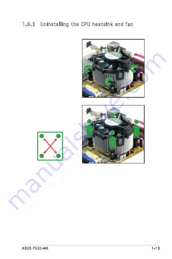
1.6.3  Uninstalling the CPU heatsink and fan

To uninstall the CPU heatsink and fan:

1.   Disconnect the CPU fan 

cable from the connector 

on the motherboard.

2.  Rotate each fastener 

counterclockwise.

3.  Pull up two fasteners at a 

time in a diagonal sequence 

to disengage the heatsink 

and fan assembly from the 

motherboard.

A

A

B

B

B

B

A

A

Содержание P5GZ-MX

Страница 1: ...Motherboard P5GZ MX ...

Страница 2: ...RTICULAR PURPOSE IN NO EVENT SHALL ASUS ITS DIRECTORS OFFICERS EMPLOYEES OR AGENTS BE LIABLE FOR ANY INDIRECT SPECIAL INCIDENTAL OR CONSEQUENTIAL DAMAGES INCLUDING DAMAGES FOR LOSS OF PROFITS LOSS OF BUSINESS LOSS OF USE OR DATA INTERRUPTION OF BUSINESS AND THE LIKE EVEN IF ASUS HAS BEEN ADVISED OF THE POSSIBILITY OF SUCH DAMAGES ARISING FROM ANY DEFECT OR ERROR IN THIS MANUAL OR PRODUCT SPECIFICA...

Страница 3: ... 3 Motherboard layout 1 7 1 6 Central Processing Unit CPU 1 8 1 6 1 Installling the CPU 1 8 1 6 2 Installling the CPU heatsink and fan 1 11 1 6 3 Uninstalling the CPU heatsink and fan 1 13 1 7 System memory 1 15 1 7 1 Overview 1 15 1 7 2 Memory configurations 1 15 1 7 3 DDR2 Qualified Vendors List 1 16 1 7 4 Installing a DIMM 1 17 1 7 5 Removing a DIMM 1 17 1 8 Expansion slots 1 18 1 8 1 Installin...

Страница 4: ...2 2 3 Navigation keys 2 12 2 2 4 Menu items 2 13 2 2 5 Sub menu items 2 13 2 2 6 Configuration fields 2 13 2 2 7 Pop up window 2 13 2 2 8 Scroll bar 2 13 2 2 9 General help 2 13 2 3 Main menu 2 14 2 3 1 System Time 2 14 2 3 2 System Date 2 14 2 3 3 Legacy Diskette A 2 14 2 3 4 Primary Third and Fourth IDE Master Slave 2 15 2 3 5 IDE Configuration 2 16 2 3 6 System Information 2 17 2 4 Advanced men...

Страница 5: ... Chapter 3 Software support 3 1 Installing an operating system 3 2 3 2 Support CD information 3 2 3 2 1 Running the support CD 3 2 3 2 2 Drivers menu 3 3 3 2 3 Utilities menu 3 4 3 2 4 Manuals menu 3 5 3 2 5 ASUS Contact information 3 6 Appendix CPU features A 1 Intel EM64T A 2 Using the Intel EM64T feature A 2 A 2 Enhanced Intel SpeedStep Technology EIST A 2 A 2 1 System requirements A 2 A 2 2 Us...

Страница 6: ...ause harmful interference to radio or television reception which can be determined by turning the equipment off and on the user is encouraged to try to correct the interference by one or more of the following measures Reorient or relocate the receiving antenna Increase the separation between the equipment and receiver Connect the equipment to an outlet on a circuit different from that to which the...

Страница 7: ...al power company If the power supply is broken do not try to fix it by yourself Contact a qualified service technician or your retailer Operation safety Before installing the motherboard and adding devices on it carefully read all the manuals that came with the package Before using the product make sure all cables are correctly connected and the power cables are not damaged If you detect any damag...

Страница 8: ...s chapter tells how to change system settings through the BIOS Setup menus Detailed descriptions of the BIOS parameters are also provided Chapter 3 Software support This chapter describes the contents of the support CD that comes with the motherboard package Where to find more information Refer to the following sources for additional information and for product and software updates 1 ASUS websites...

Страница 9: ...at you MUST follow to complete a task Bold text Indicates a menu or an item to select Italics Used to emphasize a word or a phrase Key Keys enclosed in the less than and greater than sign means that you must press the enclosed key Example Enter means that you must press the Enter or Return key Key1 Key2 Key3 If you must press two or more keys simultaneously the key names are linked with a plus sig...

Страница 10: ...chitecture 2 x 240 pin DIMM sockets support up to 2GB of unbufferred non ECC 533 400 MHz DDR2 DIMMs Integrated Intel Graphics Media Accelerator 950 1 x PCI Express x16 slot for discrete graphics cards max 2Gb s rate x4 mode 1 x PCI Express x1 2 x PCI 2 2 slots Intel ICH7 SouthBridge supports 1 x Ultra DMA 100 66 33 4 x Serial ATA 3Gb s ports Realtek ALC883 High Definition audio CODEC 6 channel aud...

Страница 11: ...XE Chassis Intrussion 2 x USB 2 0 connectors for 4 additional USB 2 0 ports 1 x CPU fan connector 1 x Chassis fan connector 1 x 24 pin EATX power connector 1 x 4 pin ATX 12 V power connector 1 x CD in connector 1 x Chassis intrusion connector 1 x Front panel high definition audio connector 1 x S PDIF out connector 1 x System Panel connector ATX power supply with 24 pin and 4 pin 12 V plugs Micro A...

Страница 12: ...xii ...

Страница 13: ...1 Product introduction This chapter describes the motherboard features and the new technologies it supports ...

Страница 14: ... drive cable Accessories I O shield Application CDs ASUS motherboard support CD Documentation User guide If any of the above items is damaged or missing contact your retailer 1 3 Special features 1 3 1 Product highlights LGA775 Intel Core 2 Processor Ready This motherboard supports the latest Intel Core 2 processor in the LGA775 package With the new Intel Core microarchitecture technology and 1066...

Страница 15: ...uirements of the latest 3D graphics multimedia and Internet applications The dual channel DDR2 architecture doubles the bandwidth of your system memory to boost system performance eliminating bottlenecks with peak bandwidths of up to 8 5 GB s See pages 1 15 to 1 17 for details PCI Express interface The motherboard fully supports PCI Express the latest I O interconnect technology that speeds up the...

Страница 16: ...ROM chip See page 2 6 for details ASUS EZ Flash BIOS With the ASUS EZ Flash you can easily update the system BIOS even before loading the operating system No need to use a DOS based utility or boot from a floppy disk See page 2 3 for details C P R CPU Parameter Recall The C P R feature of the motherboard BIOS allows automatic re setting to the BIOS default settings in case the system hangs due to ...

Страница 17: ...rom the wall socket before touching any component Use a grounded wrist strap or touch a safely grounded object or to a metal object such as the power supply case before handling components to avoid damaging them due to static electricity Hold components by the edges to avoid touching the ICs on them Whenever you uninstall any component place it on a grounded antistatic pad or in the bag that came ...

Страница 18: ...sical injury and damage motherboard components Do not overtighten the screws Doing so can damage the motherboard 1 5 1 Placement direction When installing the motherboard make sure that you place it into the chassis in the correct orientation The edge with external ports goes to the rear part of the chassis as indicated in the image below 1 5 2 Screw holes Place eight 6 screws into the holes indic...

Страница 19: ...75 CPU_FAN Super I O CHA_FAN FLOPPY PRI_IDE SATA1 SATA2 SATA3 SATA4 Intel ICH7 Intel MCH 945GZ CLRTC USB78 USB56 SPI_J1 4Mb BIOS SPDIF_OUT CD AAFP PCI2 PCI1 PCIEX16 PCIEX1_1 SB_PWR ALC883 USBPW5 8 USBPW1 4 CR2032 3V XJ2 XJ1 XJ4 XJ5 XJ3 Lithium Cell CMOS Power CHASSIS ATX12V PARALLEL PORT VGA COM1 PS 2KBMS T Mouse B Keyboard USB12 EATXPWR R Marvell 88E8001 PANEL ...

Страница 20: ...sure that the PnP cap is on the socket and the socket pins are not bent Contact your retailer immediately if the PnP cap is missing or if you see any damage to the PnP cap socket pins motherboard components ASUS will shoulder the cost of repair only if the damage is shipment transit related Keep the cap after installing the motherboard ASUS will process Return Merchandise Authorization RMA request...

Страница 21: ...ot remove the PnP cap unless you are installing a CPU 5 Position the CPU over the socket making sure that the gold triangle is on the bottom left corner of the socket The socket alignment key should fit into the CPU notch 2 Press the load lever with your thumb A and move it to the left B until it is released from the retention tab Retention tab Load lever This side of the cam box should face you P...

Страница 22: ...ent bending the connectors on the socket and damaging the CPU 6 Close the load plate A then push the load lever B until it snaps into the retention tab A B The motherboard supports Intel LGA775 processors with the Intel Enhanced Memory 64 Technology EM64T Enhanced Intel SpeedStep Technology EIST and Hyper Threading Technology ...

Страница 23: ...make sure that you use only Intel certified multi directional heatsink and fan Your I Intel Core 2 Duo Pentium D Pentium 4 or Celeron D LGA775 LGA775 heatsink and fan assembly comes in a push pin design and requires no tool to install If you purchased a separate CPU heatsink and fan assembly make sure that a Thermal Interface Material is properly applied to the CPU heatsink or CPU before you insta...

Страница 24: ...tall the chassis fan for better thermal state 3 When the fan and heatsink assembly is in place connect the CPU fan cable to the connector on the motherboard labeled CPU_FAN 2 Push down two fasteners at a time in a diagonal sequence to secure the heatsink and fan assembly in place A A B B B B A A P5GZ MX CPU Fan Connector P5GZ MX CPU_FAN GND CPU FAN PWR CPU FAN IN CPU FAN PWM R ...

Страница 25: ...ll the CPU heatsink and fan 1 Disconnect the CPU fan cable from the connector on the motherboard 2 Rotate each fastener counterclockwise 3 Pull up two fasteners at a time in a diagonal sequence to disengage the heatsink and fan assembly from the motherboard A A B B B B A A ...

Страница 26: ...the heatsink and fan assembly from the motherboard 5 Rotate each fastener clockwise to reset the orientation The narrow end of the groove should point outward after resetting The photo shows the groove shaded for emphasis Narrow end of the groove ...

Страница 27: ...all 256 MB 512 MB 1 GB and 2 GB unbuffered non ECC DDR2 DIMMs into the DIMM sockets For dual channel configuration the total size of memory module s installed per channel must be the same DIMM_A1 DIMM_B1 Always install DIMMs with the same CAS latency For optimum compatibility it is recommended that you obtain memory modules from the same vendor Refer to the DDR2 Qualified Vendors List on next page...

Страница 28: ...7 SS HYS64T32000HU 3 7 A 512MB Qimonda HYB18T512800AF37 SS HYS64T64000HU 3 7 A 512MB Qimonda HYB18T512800BF37 SS HYS64T64000HU 3 7 B 512MB Hynix HY5PS12821F C4 SS HYMP564U648 C4 1024MB Hynix HY5PS12821F C4 DS HYMP512U648 C4 1024MB Hynix HY5PS12821FP C4 DS HYMP512U648 C4 512MB Hynix HY5PS12821AFP C3 SS HYMP564U64AP8 C3 1024MB Hynix HY5PS12821AFP C3 DS HYMP512U64AP8 C3 512MB ELPIDA E5108AB 5C E SS E...

Страница 29: ... snap back in place and the DIMM is properly seated 1 7 5 Removing a DIMM Follow these steps to remove a DIMM 1 Simultaneously press the retaining clips outward to unlock the DIMM 2 Remove the DIMM from the socket A DDR2 DIMM is keyed with a notch so that it fits in only one direction Do not force a DIMM into a socket to avoid damaging the DIMM The DDR2 DIMM sockets do not support DDR DIMMs DO not...

Страница 30: ...use Keep the screw for later use 4 Align the card connector with the slot and press firmly until the card is completely seated on the slot 5 Secure the card to the chassis with the screw you removed earlier 6 Replace the system cover 1 8 2 Configuring an expansion card After installing the expansion card configure it by adjusting the software settings 1 Turn on the system and change the necessary ...

Страница 31: ...e IRQs are usually available for ISA or PCI devices IRQ assignments for this motherboard A B C D E F G H PCI slot 1 shared PCI slot 2 non shared PCI Express x16 slot shared PCI Express x1 slot shared Onboard USB controller 1 shared Onboard USB controller 2 shared Onboard USB controller 3 shared Onboard USB controller 4 shared Onboard USB 2 0 controller shared Onboard IDE port non shared Onboard HD...

Страница 32: ... one PCI Express x16 graphics card The figure shows a graphics card installed on the PCI Express x16 slot 1 8 5 PCI Express x1 This motherboard supports PCI Express x1 network cards SCSI cards and other cards that comply with the PCI Express specifications The figure shows a network card installed on the PCI Express x1 slot If you install a PCI graphics card we recommend that you remove the onboar...

Страница 33: ...0ULTRA V5 40 02 32 AS07 ASUS EN7600GS Silent 256MB V5 73 22 19 AS07 ASUS EN7600GT Silent 256M V5 73 22 15 01 ASUS EN7800GT 256MB V1 00 V5 70 02 13 AS01 ASUS EN7800GTX 256MB V5 70 02 11 01 ASUS EN7900GTX 512MX16 V5 71 22 12 01 ATI FireMV2200 V113 A25915 100 ATI Radeon X850 CrossFire V009 010 001 015 Elsa Gladiac PCX 935 W01 46W53 V4 35 20 45 E0 Elsa Gladiac 620TC 128T DVT 1A V5 44 02 11 E1 Elsa Gla...

Страница 34: ... 43 02 64 35 Leadtek Quadro FX1400 128M V5 41 02 43 03 Matrox Parhelia APVe 128M A V1 3 11 MSI NX6800GS TD256E V5 41 02 49 04 MSI NX7300GS TD256E V200 V5 72 22 34 00 MSI RX700PRO TD128E V2 00 V009 004 001 032 Powercolor Radeon X800GT 256M V009 010 001 015 Powercolor Radeon X1800XT V133 A52001 102 Set the XJ1 5 jumpers to x1 mode pin 1 2 if your graphics card cannot run at x4 mode Visit the ASUS we...

Страница 35: ...ep the cap on pins 2 3 for about 5 10 seconds then move the cap back to pins 1 2 4 Re install the battery 5 Plug the power cord and turn ON the computer 6 Hold down the Del key during the boot process and enter BIOS setup to re enter data Except when clearing the RTC RAM never remove the cap on CLRTC jumper default position Removing the cap will cause system boot failure You do not need to clear t...

Страница 36: ...slots Refer to the table below for detailed jumper setting configurations Graphics card mode Jumper Setting XJ1 XJ5 PCIE x 16 slot PCIE x 1 slot Card type speed Card type speed Add on card mode 2 3 pin PCIe graphics card or other PCIe x8 x4 device x4 N A N A Integrated Graphics mode default 1 2 pin other PCIe devices x1 other PCIe devices x1 The PCIEx1 slot is disabled when you set XJ1 5 to pins 2...

Страница 37: ...ese jumpers to 5V to wake up the computer from S1 sleep mode CPU stopped DRAM refreshed system running in low power mode using the connected USB devices Set to 5VSB to wake up from S3 and S4 sleep modes no power to CPU DRAM in slow refresh power supply in reduced power mode The USBPW1 4 jumper is for the rear USB ports USB port 1 4 The USBPW5 8 jumper is for the internal USB connectors USB port 5 ...

Страница 38: ... port green This port is for a PS 2 mouse 2 Parallel port This 25 pin port connects a parallel printer a scanner or other devices 3 LAN RJ 45 port Supported by Marvell Gigabit LAN controller this port allows Gigabit connection to a Local Area Network LAN through a network hub Refer to the table below for the LAN port LED indications 4 Line In port light blue This port connects the tape CD DVD play...

Страница 39: ...nitor or other VGA compatible devices 10 Serial port This 9 pin COM1 port is for pointing devices or other serial devices 11 PS 2 keyboard port purple This port is for a PS 2 keyboard 1 10 2 Internal connectors 1 Floppy disk drive connector 34 1 pin FLOPPY This connector is for the provided floppy disk drive FDD signal cable Insert one end of the cable to this connector then connect the other end ...

Страница 40: ...Black or gray Drive jumper Mode Cable setting of device s connector Single device Cable Select or Master Black Two devices Cable Select Master Black Slave Gray Master Master Slave Slave Pin 20 on the IDE connector is removed to match the covered hole on the Ultra DMA cable connector This prevents incorrect insertion when you connect the IDE cable Use the 80 conductor IDE cable for Ultra DMA 100 66...

Страница 41: ...to the table below for the recommended SATA hard disk drive connections Serial ATA hard disk drive connection Connector Color Setting Use SATA1 2 Red Master Boot disk SATA3 4 Black Slave Data Disk P5GZ MX SATA Connectors P5GZ MX R GND RSATA_TXP1 RSATA_TXN1 GND RSATA_RXP1 RSATA_RXN1 GND SATA1 GND RSATA_TXP2 RSATA_TXN2 GND RSATA_RXP2 RSATA_RXN2 GND SATA2 GND RSATA_TXP3 RSATA_TXN3 GND RSATA_RXP3 RSAT...

Страница 42: ...upport cooling fans of a total of 1A 2 2A 26 4W max at 12V Connect the fan cables to the fan connectors on the motherboard making sure that the black wire of each cable matches the ground pin of the connector Do not forget to connect the fan cables to the fan connectors Insufficient air flow inside the system may damage the motherboard components These are not jumpers DO NOT place jumper caps on t...

Страница 43: ...lugs make sure that the 20 pin power plug can provide at least 15A on 12V and that the PSU has a minimum power rating of 350 W The system may become unstable or may not boot up if the power is inadequate The ATX 12 V Specification 2 0 compliant PSU passed the motherboard power requirement test with the following configuration CPU Intel Pentium 4 3 6 GHz Memory 512 MB DDR x 4 Graphics card PCI Expr...

Страница 44: ...these connectors then install the module to a slot opening at the back of the system chassis These USB connectors comply with USB 2 0 specification that supports up to 480 Mbps connection speed Never connect a 1394 cable to the USB connectors Doing so will damage the motherboard The USB module is purchased separately P5GZ MX Internal Audio Connector P5GZ MX CD black Right Audio Channel Left Audio ...

Страница 45: ...ctor is for a chassis mounted front panel audio I O module that supports either HD Audio or legacy AC 97 audio standard We recommend that you connect a high definition front panel audio module to this connector to avail of the motherboard s high definition audio capability By default this connector is set to AC97 Audio If you want to connect a High Definition front panel audio module to this conne...

Страница 46: ... System warning speaker 4 pin SPEAKER This 4 pin connector is for the chassis mounted system warning speaker The speaker allows you to hear system beeps and warnings ATX power button soft off button 2 pin PWRSW This connector is for the system power button Pressing the power button turns the system on or puts the system in sleep or soft off mode depending on the BIOS settings Pressing the power sw...

Страница 47: ...2 BIOS setup This chapter tells how to change the system settings through the BIOS Setup menus Detailed descriptions of the BIOS parameters are also provided ...

Страница 48: ... DOS prompt type format A S then press Enter Windows XP environment a Insert a 1 44 MB floppy disk to the floppy disk drive b Click Start from the Windows desktop then select My Computer c Select the 3 1 2 Floppy Drive icon d Click File from the menu then select Format A Format 3 1 2 Floppy Disk window appears e Select Create an MS DOS startup disk from the format options field then click Start Wi...

Страница 49: ...n restart the system 3 Press Alt F2 during POST to display the following EZFlash starting BIOS update Checking for floppy 4 Insert the floppy disk that contains the BIOS file to the floppy disk drive When the correct BIOS file is found EZ Flash performs the BIOS update process and automatically reboots the system when done EZFlash starting BIOS update Checking for floppy Floppy found Reading file ...

Страница 50: ...then at the prompt type afudos o filename where the filename is any user assigned filename not more than eight alphanumeric characters for the main filename and three alphanumeric characters for the extension name A afudos oOLDBIOS1 rom Make sure that the floppy disk is not write protected and has at least 1024KB free space to save the file The succeeding BIOS screens are for reference only The ac...

Страница 51: ... Reboot the system from the hard disk drive A afudos iP5GZMX ROM AMI Firmware Update Utility Version 1 19 ASUS V2 07 03 11 24BB Copyright C 2002 American Megatrends Inc All rights reserved WARNING Do not turn off power during flash BIOS Reading file done Reading flash done Advance Check Erasing flash done Writing flash done Verifying flash done Please restart your computer A A afudos iP5GZMX ROM A...

Страница 52: ...d BIOS file to the floppy disk drive 3 The utility displays the following message and automatically checks the floppy disk for the original or updated BIOS file Bad BIOS checksum Starting BIOS recovery Checking for floppy 4 Restart the system after the utility completes the updating process Bad BIOS checksum Starting BIOS recovery Checking for floppy Floppy found Reading file P5GZMX ROM Completed ...

Страница 53: ...system boot failure Bad BIOS checksum Starting BIOS recovery Checking for floppy Floppy not found Checking for CD ROM CD ROM found Reading file P5GZMX ROM Completed Start flashing When no floppy disk is found the utility automatically checks the optical drive for the original or updated BIOS file The utility then updates the corrupted BIOS file Bad BIOS checksum Starting BIOS recovery Checking for...

Страница 54: ...the motherboard BIOS in Windows environment The ASUS Update utility allows you to Save the current BIOS file Download the latest BIOS file from the Internet Update the BIOS from an updated BIOS file Update the BIOS directly from the Internet and View the BIOS version information This utility is available in the support CD that comes with the motherboard package ASUS Update requires an Internet con...

Страница 55: ...Updating the BIOS through the Internet To update the BIOS through the Internet 1 Launch the ASUS Update utility from the Windows desktop by clicking Start Programs ASUS ASUSUpdate ASUSUpdate The ASUS Update main window appears 2 Select Update BIOS from the Internet option from the drop down menu then click Next ...

Страница 56: ...date BIOS from a file option from the drop down menu then click Next 4 From the FTP site select the BIOS version that you wish to download Click Next 5 Follow the screen instructions to complete the update process The ASUS Update utility is capable of updating itself through the Internet Always update the utility to avail all its features 3 Locate the BIOS file from the Open window then click Open...

Страница 57: ...ress Del during the Power On Self Test POST to enter the Setup utility otherwise POST continues with its test routines If you wish to enter Setup after POST restart the system by pressing Ctrl Alt Delete or by pressing the reset button on the system chassis You can also restart by turning the system off and then back on Do this last option only if the first two failed The Setup program is designed...

Страница 58: ...ress the right or left arrow key on the keyboard until the desired item is highlighted Some of the navigation keys differ from one screen to another Navigation keys General help Menu bar Sub menu items Configuration fields Menu items 2 2 3 Navigation keys At the bottom right corner of a menu screen are the navigation keys for that particular menu Use the navigation keys to select items in the menu...

Страница 59: ...screen when there are items that do not fit on the screen Press the Up Down arrow keys or Page Up Page Down keys to display the other items on the screen 2 2 9 General help At the top right corner of the menu screen is a brief description of the selected item Scroll bar Select Screen Select Item Change Option F1 General Help F10 Save and Exit ESC Exit Advanced Chipset settings WARNING Setting wron...

Страница 60: ...uration options Disabled 360K 5 25 in 1 2M 5 25 in 720K 3 5 in 1 44M 3 5 in 2 88M 3 5 in Refer to section 2 2 1 BIOS menu screen for information on the menu screen items and how to navigate through them Use ENTER TAB or SHIFT TAB to select a field Use or to configure system time System Time 11 51 19 System Date Thu 05 07 2004 Legacy Diskette A 1 44M 3 5 in Primary IDE Master ST320413A Primary IDE ...

Страница 61: ...120 or MO drive Configuration options Not Installed Auto CDROM ARMD LBA Large Mode Auto Enables or disables the LBA mode Setting to Auto enables the LBA mode if the device supports this mode and if the device was not previously formatted with LBA mode disabled Configuration options Disabled Auto Block Multi sector Transfer Auto Enables or disables data multi sectors transfers When set to Auto the ...

Страница 62: ...nfiguration options Disabled Enabled 2 3 5 IDE Configuration The items in this menu allow you to set or change the configurations for the IDE devices installed in the system Select an item then press Enter if you wish to configure the item IDE Configuration Onboard IDE Operate Mode Enhanced Mode Enhanced Mode Support On S ATA IDE Detect Time Out Sec 35 Onboard IDE Operate Mode Enhanced Mode Disabl...

Страница 63: ...e default setting S ATA Configuration options S ATA P ATA S ATA P ATA IDE Detect Time Out 35 Selects the time out value for detecting ATA ATAPI devices Configuration options 0 5 10 15 20 25 30 35 2 3 6 System Information This menu gives you an overview of the general system specifications The BIOS automatically detects the items in this menu AMI BIOS Displays the auto detected BIOS information Pro...

Страница 64: ...guration CPU Configuration Chipset Onboard Devices Configuration PCI PnP 2 4 1 JumperFree Configuration AI Overclocking Auto Allows selection of CPU overclocking options to achieve desired CPU internal frequency Select either one of the preset overclocking configuration options Manual allows you to individually set overclocking parameters Auto loads the optimal settings for the system Configure Sy...

Страница 65: ...o Manual CPU Frequency 200 Displays the frequency sent by the clock generator to the system bus The value of this item is auto detected by the BIOS The values range from 100 to 450 Memory Voltage Auto Allows you to select the memory voltage or set it to Auto for safe mode Configuration options Auto 1 80V 1 85V 1 90V 1 95V Selecting a very high Memory voltage may damage the component permanently If...

Страница 66: ...est POST Configuration options Disabled Enabled Select Screen Select Item Change Field Tab Select Field F1 General Help F10 Save and Exit ESC Exit v02 58 C Copyright 1985 2006 American Megatrends Inc BIOS SETUP UTILITY Advanced POST Check LAN cable Disabled LAN Cable Status Pair Status Length 1 2 N A 3 6 N A 4 5 N A 7 8 N A Check LAN cable during POST ...

Страница 67: ...ure the USB 2 0 controller in HiSpeed 480 Mbps or Full Speed 12 Mbps Configuration options HiSpeed Full Speed BIOS EHCI Hand off Disabled Allows you to enable support for operating systems without an EHCI hand off feature Configuration options Enabled Disabled The Module Version and USB Devices Enabled items show the auto detected values If no USB device is detected the item shows None 2 4 3 USB C...

Страница 68: ...rol Auto Sets the ratio between CPU Core Clock and the FSB Frequency NOTE If an invalid ratio is set in CMOS then actual and setpoint values may differ Ratio CMOS Setting 6 Sets the ratio between the CPU Core Clock and the Front Side Bus frequency The default value of this item is auto detected by BIOS Use the or keys to adjust the values VID CMOS Setting 62 Allows you to set the VID CMOS setting ...

Страница 69: ...mum or Disabled if you do not want to use the EIST The CPU constantly operates at a lower internal frequency when you set this item to Minimum Configuration options Maximum Minimum Automatic Disabled 2 4 5 Chipset The Chipset menu allows you to change the advanced chipset settings Select an item then press Enter to display the sub menu Select Screen Select Item Change Option F1 General Help F10 Sa...

Страница 70: ...ions 2 Clocks 3 Clocks 4 Clocks 5 Clocks 6 Clocks DRAM RAS Activate to Precha 15 Clocks Sets the RAS Activate timing to Precharge timing Configuration options 1 Clock 2 Clocks 18 Clocks DRAM Write Recovery Time 4 Clocks Sets the DRAM Write Recover Time Configuration options 2 Clocks 3 Clocks 4 Clocks 5 Clocks 6 Clocks Booting Graphic Adapter Priority Internal VGA Allows selection of the graphics c...

Страница 71: ... high definition audio depending on the audio standard that the front panel audio module supports Configuration options AC97 HD Audio OnBoard PCI GbE LAN Enabled Allows you to enable or disable the onboard PCI Gigabit LAN controller Configuration options Disabled Enabled PCI LAN Option ROM Disabled Allows you to enable or disable the option ROM in the onboard LAN controller This item appears only ...

Страница 72: ... ECP Mode DMA Channel DMA3 Appears only when the Parallel Port Mode is set to ECP This item allows you to set the Parallel Port ECP DMA Configuration options DMA0 DMA1 DMA3 Parallel Port IRQ IRQ7 Configuration options IRQ5 IRQ7 ...

Страница 73: ... PCI Device IRQ 10 assigned to PCI Device IRQ 11 assigned to PCI Device IRQ 14 assigned to PCI Device IRQ 15 assigned to PCI Device Plug and Play O S No When set to No BIOS configures all the devices in the system When set to Yes and if you install a Plug and Play operating system the operating system configures the Plug and Play devices not required for boot Configuration options No Yes PCI Laten...

Страница 74: ...erface ACPI state to be used for system suspend Configuration options S1 POS Only S3 Only Auto 2 5 2 ACPI 2 0 Support No Allows you to add more tables for Advanced Configuration and Power Interface ACPI 2 0 specifications Configuration options No Yes 2 5 3 ACPI APIC Support Enabled Allows you to enable or disable the Advanced Configuration and Power Interface ACPI support in the Application Specif...

Страница 75: ...ration options Power Off Power On Last State Power On By RTC Alarm Disabled Allows you to enable or disable RTC to generate a wake event When this item is set to Enabled the items RTC Alarm Date RTC Alarm Hour RTC Alarm Minute and RTC Alarm Second appear with set values Configuration options Disabled Enabled Power On By External Modems Disabled This allows either settings of Enabled or Disabled fo...

Страница 76: ... On By PS 2 Keyboard Disabled Allows you to use specific keys on the keyboard to turn on the system This feature requires an ATX power supply that provides at least 1A on the 5VSB lead Configuration options Disabled Space Bar Ctrl Esc Power Key Power On By PS 2 Mouse Disabled When set to Enabled this parameter allows you to use the PS 2 mouse to turn on the system This feature requires an ATX powe...

Страница 77: ...or Ignored The onboard hardware monitor automatically detects and displays the CPU fan speed in rotations per minute RPM If the fan is not connected to the motherboard the field shows N A Configuration options Ignored xxxRPM CPU Q Fan Control Disabled Allows you to enable or disable the ASUS Q Fan feature that smartly adjusts the fan speeds for more efficient system operation Configuration options...

Страница 78: ... Security 2 6 1 Boot Device Priority 1st xxth Boot Device 1st Floppy Drive These items specify the boot device priority sequence from the available devices The number of device items that appears on the screen depends on the number of devices installed in the system Configuration options xxxxx Drive Disabled Select Screen Select Item Enter Go to Sub screen F1 General Help F10 Save and Exit ESC Exi...

Страница 79: ... When set to Disabled BIOS performs all the POST items Configuration options Disabled Enabled Full Screen Logo Enabled This allows you to enable or disable the full screen logo display feature Configuration options Disabled Enabled Add On ROM Display Mode Force BIOS Sets the display mode for option ROM Configuration options Force BIOS Keep Current Bootup Num Lock On Allows you to select the power ...

Страница 80: ...rd Not Installed Change Supervisor Password Enter to change password Enter again to disabled password Change Supervisor Password Select this item to set or change the supervisor password The Supervisor Password item on top of the screen shows the default Not Installed After you set a password this item shows Installed To set a Supervisor Password 1 Select the Change Supervisor Password item and pr...

Страница 81: ... item on top of the screen shows the default Not Installed After you set a password this item shows Installed To set a User Password 1 Select the Change User Password item and press Enter 2 On the password box that appears type a password composed of at least six letters and or numbers then press Enter 3 Confirm the password when prompted The message Password Installed appears after you set your p...

Страница 82: ...oad the optimal or failsafe default values for the BIOS items and save or discard your changes to the BIOS items Exit Options Exit Save Changes Exit Discard Changes Discard Changes Load Setup Defaults Exit Save Changes Once you are finished making your selections choose this option from the Exit menu to ensure the values you selected are saved to the CMOS RAM An onboard backup battery sustains the...

Страница 83: ...ard the selections you made and restore the previously saved values After selecting this option a confirmation appears Select Ok to discard any changes and load the previously saved values Load Setup Defaults This option allows you to load the default values for each of the parameters on the Setup menus When you select this option or if you press F5 a confirmation window appears Select Ok to load ...

Страница 84: ...2 38 Chapter 2 BIOS setup ...

Страница 85: ...3 Software support This chapter describes the contents of the support CD that comes with the motherboard package ...

Страница 86: ...tilities that you can install to avail all motherboard features 3 2 1 Running the support CD Place the support CD to the optical drive The CD automatically displays the Drivers menu if Autorun is enabled in your computer Motherboard settings and hardware options vary Use the setup procedures presented in this chapter for reference only Refer to your OS documentation for detailed information Make s...

Страница 87: ...ver provides the method for configuring the chipset components You can install this utility using three different modes interactive silent or unattended preload Installing the driver in interactive mode requires user input during installation User input is not required when installing the driver in silent or unattended preload modes Refer to the online help or readme file that came with the utilit...

Страница 88: ... II This smart utility monitors the fan speed CPU temperature and system voltages and alerts you of any detected problems This utility helps you keep your computer in healthy operating condition ASUS Update The ASUS Update utility allows you to update the motherboard BIOS in a Windows environment This utility requires an Internet connection either through a network or an Internet Service Provider ...

Страница 89: ...games in your computer Visit the Microsoft website www microsoft com for updates Anti Virus Utility The anti virus application scans identifies and removes computer viruses View the online help for detailed information 3 2 4 Manuals menu The Manuals menu contains a list of supplementary user manuals Click an item to open the folder of the user manual Most user manual files are in Portable Document...

Страница 90: ...3 Chapter 3 Software support 3 2 5 ASUS Contact information Click the Contact tab to display the ASUS contact information You can also find this information on the inside front cover of this user guide ...

Страница 91: ...A CPU features The Appendix describes the CPU features that the motherboard supports ...

Страница 92: ...tion 3 Install the 64 bit drivers for the motherboard components and devices from the support CD 4 Install the 64 bit drivers for expansion cards or add on devices if any Refer to the expansion card or add on device s documentation or visit the related website to verify if the card device supports a 64 bit system A 2 Enhanced Intel SpeedStep Technology EIST The motherboard comes with a BIOS file t...

Страница 93: ...ank space on the desktop then select Properties from the pop up menu 6 When the Display Properties window appears click the Screen Saver tab 7 Click the Power button on the Monitor power section to open the Power Options Properties window 8 On the Power schemes section click then select any option except Home Office Desktop or Always On 9 Click Apply then click OK 10 Close the Display Properties w...

Страница 94: ...talling Windows XP Service Pack 1 or later version is recommended Make sure to enable the Hyper Threading Technology item in BIOS before installing a supported operating system For more information on Hyper Threading Technology visit www intel com info hyperthreading Using the Hyper Threading Technology To use the Hyper Threading Technology 1 Install an Intel Pentium 4 CPU that supports Hyper Thre...

Отзывы: