


ASUS P5GC-MX/1333
2-31
2.6
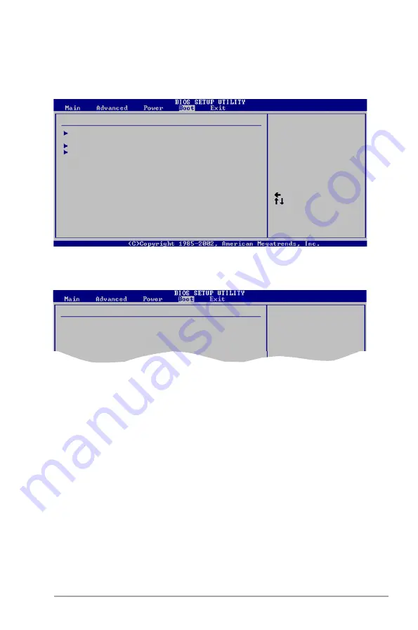
Boot menu
The Boot menu items allow you to change the system boot options. Select an item
then press <Enter> to display the sub-menu.
Select Screen
Select Item
Enter Go to Sub-screen
F1 General Help
F10 Save and Exit
ESC Exit
Boot Settings
Boot Device Priority
Boot Settings Configuration
Security
2.6.1
Boot Device Priority
1st ~ xxth Boot Device [1st Floppy Drive]
These items specify the boot device priority sequence from the available devices.
The number of device items that appears on the screen depends on the number of
devices installed in the system.
Configuration options: [xxxxx Drive] [Disabled]
Select Screen
Select Item
Enter Go to Sub-screen
F1 General Help
F10 Save and Exit
ESC Exit
Boot Device Priority
1st Boot Device
[1st FLOPPY DRIVE]
2nd Boot Device
[Hard Drive]
3rd Boot Device
[PS- DVD-E616P3]
Содержание P5GC MX 1333 - Motherboard - Micro ATX
Страница 1: ...Motherboard P5GC MX 1333 ...
Страница 12: ...xii ...
Страница 13: ...1 Product introduction This chapter describes the motherboard features and the new technologies it supports ...
Страница 46: ...1 34 Chapter 1 Product introduction ...
Страница 89: ...A CPU features The Appendix describes the CPU features that the motherboard supports ...


