background image

ASUS P5G41T-M/USB3

2-1

Chapter 2

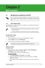
BIOS information

Save a copy of the original motherboard BIOS file to a USB flash disk in case you need to 

restore the BIOS in the future. Copy the original motherboard BIOS using the ASUS Update 

utility.

•  ASUS Update requires an Internet connection either through a network or an Internet 

Service Provider (ISP).

•  This utility is available in the support DVD that comes with the motherboard package.

Updating the BIOS

To update the BIOS:
1. 

From the Windows

®

 desktop, click 

Start 

>

 Programs 

>

 ASUS 

>

 ASUSUpdate 

>


ASUSUpdate

 to launch the ASUS Update utility. 

2. 

From the dropdown list, select any of the updating process:

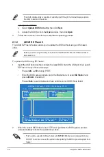
Updating from the Internet


a.  Select 

Update BIOS


from the Internet

, then click 

Next

.


b.  Select the ASUS FTP site nearest you to avoid network traffic, or click 

Auto    


Select

 then click 

Next

.


c.  From the FTP site, select the BIOS version that you wish to download then click  


Next

.

2.1.1 

ASUS Update utility

The ASUS Update is a utility that allows you to manage, save, and update the motherboard 

BIOS in Windows

®

 environment. 

Installing ASUS Update

To install ASUS Update:
1. 

Place the support DVD in the optical drive. The 

Drivers

 menu appears. 

2. 

Click the 

Utilities

 tab, then click

 ASUS Update

3. 

Follow the onscreen instructions to complete the installation.

Quit all Windows

®

 applications before you update the BIOS using this utility.

2.1 

Managing and updating your BIOS

Содержание P5G41T-M USB3

Страница 1: ...Motherboard P5G41T M USB3 ...

Страница 2: ...lanation and to the owners benefit without intent to infringe Offer to Provide Source Code of Certain Software This product may contain copyrighted software that is licensed under the General Public License GPL and under the Lesser General Public License Version LGPL The GPL and LGPL licensed code in this product is distributed without any warranty Copies of these licenses are included in this pro...

Страница 3: ...5 4 Layout contents 1 7 1 6 Central Processing Unit CPU 1 8 1 6 1 Installing the CPU 1 8 1 6 2 Installing the CPU heatsink and fan 1 11 1 6 3 Uninstalling the CPU heatsink and fan 1 12 1 7 System memory 1 13 1 7 1 Overview 1 13 1 7 2 Memory configurations 1 14 1 7 3 Installing a DIMM 1 16 1 7 4 Removing a DIMM 1 16 1 8 Expansion slots 1 17 1 8 1 Installing an expansion card 1 17 1 8 2 Configuring ...

Страница 4: ... 2 6 2 2 5 Submenu items 2 6 2 2 6 Configuration fields 2 6 2 2 7 Pop up window 2 6 2 2 8 Scroll bar 2 6 2 2 9 General help 2 6 2 3 Main menu 2 7 2 3 1 System Time 2 7 2 3 2 System Date 2 7 2 3 3 Primary IDE Master Slave SATA1 4 2 7 2 3 4 Storage Configuration 2 8 2 3 5 System Information 2 9 2 4 Advanced menu 2 9 2 4 1 JumperFree Configuration 2 9 2 4 2 CPU Configuration 2 11 2 4 3 Chipset 2 12 2...

Страница 5: ...ration 2 16 2 5 6 Hardware Monitor 2 16 2 6 Boot menu 2 17 2 6 1 Boot Device Priority 2 17 2 6 2 Boot Settings Configuration 2 17 2 6 3 Security 2 18 2 7 Tools menu 2 20 2 7 1 ASUS EZ Flash 2 2 20 2 7 2 Express Gate 2 20 2 7 3 AI NET 2 2 20 2 8 Exit menu 2 21 ...

Страница 6: ...t from that to which the receiver is connected Consult the dealer or an experienced radio TV technician for help Canadian Department of Communications Statement This digital apparatus does not exceed the Class B limits for radio noise emissions from digital apparatus set out in the Radio Interference Regulations of the Canadian Department of Communications This class B digital apparatus complies w...

Страница 7: ...peration safety Before installing the motherboard and adding devices on it carefully read all the manuals that came with the package Before using the product ensure that all cables are correctly connected and the power cables are not damaged If you detect any damage contact your dealer immediately To avoid short circuits keep paper clips screws and staples away from connectors slots sockets and ci...

Страница 8: ...uct and software updates 1 ASUS websites The ASUS website provides updated information on ASUS hardware and software products Refer to the ASUS contact information 2 Optional documentation Your product package may include optional documentation such as warranty flyers that may have been added by your dealer These documents are not part of the standard package Typography Bold text Indicates a menu ...

Страница 9: ...he latest Memory QVL Qualified Vendors Lists When you install a total memory of 4GB or more Windows 32 bit operating system may only recognize less than 3GB We recommend a maximum of 3GB system memory if you are using a Windows 32 bit operating system Graphics Integrated Intel GMA X4500 GPU Supports HDMI with max resolution of 1920 x 1080 60Hz Supports RGB with max resolution of 2048 x 1536 75Hz S...

Страница 10: ...jacks Internal connectors 2 x USB 2 0 1 1 connectors support additional 4 USB 2 0 1 1 ports 1 x IDE connector 4 x Serial ATA connectors 1 x Front panel audio connector 1 x System panel connector 1 x S PDIF Out connector 1 x LPT connector 1 x COM connector 1 x CPU fan connector 1 x Chassis fan connector 1 x 24 pin EATX power connector 1 x 4 pin ATX 12V power connector BIOS 8Mb Flash ROM AMI BIOS Pn...

Страница 11: ...rts Intel LGA775 Core 2 Extreme Core 2 Quad Core 2 Duo processors which are excellent for multitasking multimedia and enthusiastic gamers with 1333 1066 800MHz FSB This motherboard also supports Intel CPUs in the 45nm manufacturing process 1 1 Welcome Thank you for buying an ASUS P5G41T M USB3 motherboard The motherboard delivers a host of new features and latest technologies making it another sta...

Страница 12: ... and retrieval Gigabit LAN solution The onboard LAN controller is a highly integrated Gb LAN controller It is enhanced with an ACPI management function to provide efficient power management for advanced operating systems USB 3 0 support Experience ultra fast data transfer at 4 8Gbps with USB 3 0 the latest connectivity standard Built to connect easily with next generation components and peripheral...

Страница 13: ...and the motherboard from damage caused by power surges from switching power supply ASUS Express Gate Express Gate is an ASUS exclusive OS which lets you instantly access the Internet and key applications before entering the Windows OS ASUS Express Gate supports installation on SATA HDDs USB HDDs and flash drives with at least 1 2GB free disk space When installing it on USB HDDs or flash drives con...

Страница 14: ...tically restores the CPU default settings when the system hangs due to overclocking failure C P R eliminates the need to open the system chassis and clear the RTC data Simply shut down and reboot the system and the BIOS automatically restores the CPU parameters to their default settings Green ASUS This motherboard and its packaging comply with the European Union s Restriction on the use of Hazardo...

Страница 15: ... it on a grounded antistatic pad or in the bag that came with the component Before you install or remove any component ensure that the ATX power supply is switched off or the power cord is detached from the power supply Failure to do so may cause severe damage to the motherboard peripherals or components Onboard LED The motherboard comes with a standby power LED that lights up to indicate that the...

Страница 16: ...injury and damage motherboard components 1 5 1 Placement direction When installing the motherboard ensure that you place it into the chassis in the correct orientation The edge with external ports goes to the rear part of the chassis as indicated in the image below 1 5 2 Screw holes Place six screws into the holes indicated by circles to secure the motherboard to the chassis Do not overtighten the...

Страница 17: ...3 14 1 6 7 8 1 5 4 Layout contents Connectors Jumpers Slots LED Page Connectors Jumpers Slots LED Page 1 ATX power connectors 24 pin EATXPWR 4 pin ATX12V 1 22 8 Onboard power LED SB_PWR 1 5 2 CPU and chassis fan connectors 4 pin CPU_FAN 3 pin CHA_FAN 1 21 9 System panel connector 20 8 pin PANEL 1 25 3 Intel LGA775 CPU socket 1 8 10 USB connectors 10 1 pin USB56 USB78 1 26 4 DDR3 DIMM slots 1 13 11...

Страница 18: ...t contacts motherboard components ASUS will shoulder the cost of repair only if the damage is shipment transit related Keep the cap after installing the motherboard ASUS will process Return Merchandise Authorization RMA requests only if the motherboard comes with the cap on the LGA775 socket The product warranty does not cover damage to the socket contacts resulting from incorrect CPU installation...

Страница 19: ...etention tab 4 Lift the load plate with your thumb and forefinger to a 100º angle 4A then push the PnP cap from the load plate window to remove 4B 3 Lift the load lever in the direction of the arrow to a 135º angle PnP cap Load plate 4A 4B 3 5 Position the CPU over the socket ensuring that the gold triangle is on the bottom left corner of the socket then fit the socket alignment key into the CPU n...

Страница 20: ...eat the Thermal Interface Material If it gets into your eyes or touches your skin ensure that you wash it off immediately and seek professional medical help Some heatsinks come with pre applied thermal paste If so skip this step To prevent contaminating the paste DO NOT spread the paste with your finger directly 7 Close the load plate A then push the load lever B until it snaps into the retention ...

Страница 21: ... properly applied Thermal Interface Material to the CPU heatsink or CPU before you install the heatsink and fan assembly Ensure that you have installed the motherboard to the chassis before you install the CPU fan and heatsink assembly The type of CPU heatsink and fan assembly may differ but the installation steps and functions should remain the same The illustration above is for reference only To...

Страница 22: ...nnector CPU_FAN CPU FAN PWM CPU FAN IN CPU FAN PWR GND P5G41T M USB3 CPU fan connector P5G41T M USB3 1 6 3 Uninstalling the CPU heatsink and fan To uninstall the CPU heatsink and fan 1 Disconnect the CPU fan cable from the connector on the motherboard 2 Rotate each fastener counterclockwise 3 Pull up two fasteners at a time in a diagonal sequence to disengage the heatsink and fan assembly from the...

Страница 23: ...M sockets The figure illustrates the location of the DDR3 DIMM sockets P5G41T M USB3 240 pin DDR3 DIMM sockets DIMM_A1 DIMM_B1 P5G41T M USB3 Channel Sockets Channel A DIMM_A1 Channel B DIMM_B1 4 Carefully remove the heatsink and fan assembly from the motherboard 5 Rotate each fastener clockwise to ensure correct orientation when reinstalling ...

Страница 24: ...essing information from a memory module Under the default state some memory modules for overclocking may operate at a lower frequency than the vendor marked value For system stability use a more efficient cooling system to support a full memory load 2 DIMMs or overclocking conditions P5G41T M USB3 Motherboard Qualified Vendors Lists QVL DDR3 1066 MHz capability Vendor Part No Size SS DS Chip Brand...

Страница 25: ...MB DS ELPIDA J1108EDSE DJ F 1 35V low voltage G SKILL F3 10600CL9D 2GBPK 1024MB SS G SKILL G SKILL F3 10600CL7D 2GBPI 1024MB DS G SKILL G SKILL F3 10600CL9D 2GBNQ 1024MB DS G SKILL G SKILL F3 10666CL9T 6GBNQ 6144MB Kit of 3 DS 9 9 9 24 1 5V 1 6V Kingmax FLFD45F B8MF9 1024MB SS Micron 8HD22D9JNM Kingmax FLFD45F B8MH9 MAES 1024MB SS Micron 9CF22D9KPT Kingmax FLFE85F B8MF9 2048MB DS Micron 8HD22D9JNM...

Страница 26: ... into a socket in the wrong direction to avoid damaging the DIMM 3 Hold the DIMM by both of its ends then insert the DIMM vertically into the socket Apply force to both ends of the DIMM simultaneously until the retaining clip snaps back into place and the DIMM cannot be pushed in any further to ensure proper sitting of the DIMM Locked Retaining Clip 3 1 7 4 Removing a DIMM To remove a DIMM 1 Simul...

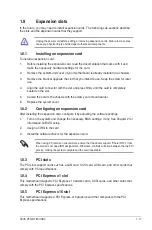
Страница 27: ...assis with the screw you removed earlier 6 Replace the system cover 1 8 2 Configuring an expansion card After installing the expansion card configure it by adjusting the software settings 1 Turn on the system and change the necessary BIOS settings if any See Chapter 2 for information on BIOS setup 2 Assign an IRQ to the card 3 Install the software drivers for the expansion card When using PCI card...

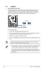
Страница 28: ...ar RTC CLRTC If the steps above do not help remove the onboard battery and move the jumper again to clear the CMOS RTC RAM data After clearing the CMOS reinstall the battery You do not need to clear the RTC when the system hangs due to overclocking For system failure due to overclocking use the CPU Parameter Recall C P R feature Shut down and reboot the system then the BIOS automatically resets pa...

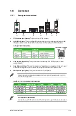
Страница 29: ...Out port lime This port connects to a headphone or a speaker In the 4 6 and 8 channel configurations the function of this port becomes Front Speaker Out 5 Microphone port pink This port connects to a microphone LAN port SPEED LED ACT LINK LED Refer to the audio configuration table below for the function of the audio ports in a 2 4 6 or 8 channel configuration Audio 2 4 6 or 8 channel configuration...

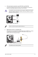
Страница 30: ...FP This connector is for a chassis mounted front panel audio I O module that supports either HD Audio or legacy AC 97 audio standard Connect one end of the front panel audio I O module cable to this connector P5G41T M USB3 P5G41T M USB3 Front panel audio connector AAFP PIN 1 GND PRESENCE SENSE1_RETUR SENSE2_RETUR PORT1 L PORT1 R PORT2 R SENSE_SEND PORT2 L HD audio compliant pin definition PIN 1 AG...

Страница 31: ...rs Do not place jumper caps on the fan connectors CPU_FAN CPU FAN PWM CPU FAN IN CPU FAN PWR GND P5G41T M USB3 fan connectors GND 12V Rotation CHA_FAN P5G41T M USB3 Only the 4 pin CPU fan supports the ASUS Q FAN feature 3 Digital audio connector 4 1 pin SPDIF_OUT This connector is for an additional Sony Philips Digital Interface S PDIF port Connect the S PDIF Out module cable to this connector the...

Страница 32: ...wer rating This PSU type has 24 pin and 4 pin power plugs If you intend to use a PSU with 20 pin and 4 pin power plugs ensure that the 20 pin power plug can provide at least 15 A on 12 V and that the PSU has a minimum power rating of 400W The system may become unstable or may not boot up if the power is inadequate DO NOT forget to connect the 4 pin ATX 12V power plug Otherwise the system will not ...

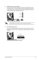
Страница 33: ...TA_TXN2 GND RSATA_RXP2 RSATA_RXN2 GND SATA4 GND RSATA_TXP4 RSATA_TXN4 GND RSATA_RXP4 RSATA_RXN4 GND SATA1 GND RSATA_RXN1 RSATA_RXP1 GND RSATA_TXN1 RSATA_TXP1 GND P5G41T M USB3 SATA connectors P5G41T M USB3 Install the Windows XP Service Pack 2 or later version before using Serial ATA 6 LPT connector 26 1 pin LPT The LPT Line Printing Terminal connector supports devices such as a printer LPT is sta...

Страница 34: ...ble connector Single device Cable Select or Master Black Two devices Cable Select Master Black Slave Gray Master Master Black or gray Slave Slave Pin 20 on the IDE connector is removed to match the covered hole on the Ultra DMA cable connector This prevents incorrect insertion when you connect the IDE cable Use the 80 conductor IDE cable for Ultra DMA 100 66 33 IDE devices PRI_IDE NOTE Orient the ...

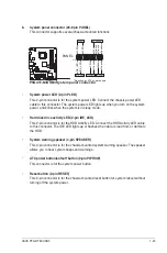
Страница 35: ...ou turn on the system power and blinks when the system is in sleep mode Hard disk drive activity LED 2 pin IDE_LED This 2 pin connector is for the HDD Activity LED Connect the HDD Activity LED cable to this connector The IDE LED lights up or flashes when data is read from or written to the HDD System warning speaker 4 pin SPEAKER This 4 pin connector is for the chassis mounted system warning speak...

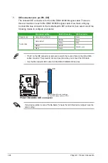
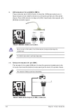
Страница 36: ...ctors USB 5V USB_P6 USB_P6 GND NC USB 5V USB_P5 USB_P5 GND USB56 PIN 1 USB 5V USB_P8 USB_P8 GND NC USB 5V USB_P7 USB_P7 GND USB78 PIN 1 Never connect a 1394 cable to the USB connectors Doing so will damage the motherboard The USB module cable is purchased separately 10 Serial port connector 10 1 pin COM1 The connector is for a serial COM port Connect the serial port module cable to the connector t...

Страница 37: ...tains the drivers software applications and utilities that you can install to avail all motherboard features If Autorun is NOT enabled in your computer browse the contents of the Support DVD to locate the file ASSETUP EXE from the BIN folder Double click the ASSETUP EXE to run the DVD The following screen is for reference only Click an item to install Click an icon to display Support DVD motherboa...

Страница 38: ...1 28 Chapter 1 Product introduction ...

Страница 39: ...n list select any of the updating process Updating from the Internet a Select Update BIOS from the Internet then click Next b Select the ASUS FTP site nearest you to avoid network traffic or click Auto Select then click Next c From the FTP site select the BIOS version that you wish to download then click Next 2 1 1 ASUS Update utility The ASUS Update is a utility that allows you to manage save and...

Страница 40: ...s the BIOS update process and automatically reboots the system when done The ASUS Update utility is capable of updating itself through the Internet Always update the utility to avail all its features Updating from a BIOS file a Select Update BIOS from a file then click Next b Locate the BIOS file from the Open window then click Open 3 Follow the onscreen instructions to complete the updating proce...

Страница 41: ...r motherboards without the floppy connector prepare a USB flash disk before using this utility Recovering the BIOS To recover the BIOS 1 Turn on the system 2 Insert the support DVD to the optical drive or the removable device that contains the BIOS file to the USB port or to the floppy disk drive if supported 3 The utility automatically checks the devices for the BIOS file When found the utility r...

Страница 42: ... you failed to enter BIOS Setup using the first two options Using the power button reset button or the Ctrl Alt Del keys to force reset from a running operating system can cause damage to your data or system We recommend to always shut down the system properly from the operating system The default BIOS settings for this motherboard apply for most conditions to ensure optimum performance If the sys...

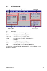
Страница 43: ...ft arrow key on the keyboard until the desired item is highlighted 2 2 1 BIOS menu screen v02 61 C Copyright 1985 2010 American Megatrends Inc System Time 00 31 48 System Date Fri 01 25 2002 Primary IDE Master Not Detected Primary IDE Slave Not Detected SATA 1 Not Detected SATA 2 Not Detected SATA 3 Not Detected SATA 4 Not Detected Storage Configuration System Information Use ENTER TAB or SHIFT TA...

Страница 44: ...d Power Boot Tools and Exit on the menu bar have their respective menu items 2 2 5 Submenu items A solid triangle before each item on any menu screen means that the item has a submenu To display the submenu select the item and press Enter 2 2 6 Configuration fields These fields show the values for the menu items If an item is user configurable you can change the value of the field opposite the ite...

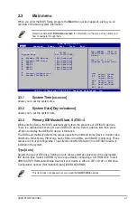
Страница 45: ... Type Auto Selects the type of IDE drive Setting to Auto allows automatic selection of the appropriate IDE device type Select CDROM if you are specifically configuring a CD ROM drive Select ARMD ATAPI Removable Media Device if your device is either a ZIP LS 120 or MO drive Configuration options Not Installed Auto CDROM ARMD Select Screen Select Item Change Field Tab Select Field F1 General Help F1...

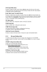
Страница 46: ...A Mode Auto Selects the DMA mode Configuration options Auto SMART Monitoring Auto Sets the Smart Monitoring Analysis and Reporting Technology Configuration options Auto Disabled Enabled 32Bit Data Transfer Enabled Enables or disables 32 bit data transfer Configuration options Disabled Enabled 2 3 4 Storage Configuration The items in this menu allow you to set or change the configurations for the S...

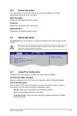
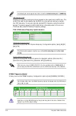
Страница 47: ...Enables or disables clock for PCI PCIe slot Configuration options Enabled Disabled AI Overclocking Auto Allows selection of CPU overclocking options to achieve desired CPU internal frequency Select either one of the preset overclocking configuration options Manual allows you to individually set overclocking parameters Auto loads the optimal settings for the system Overclock Profile loads overclock...

Страница 48: ... 1067MHz 1100MHz 1333MHz 1333 v v v v 1066 v v v 800 v v The following table shows the DRAM Frequency options that appear when the FSB value is 1333 1066 and 800 CPU Frequency xxx Displays the frequency sent by the clock generator to the system bus and PCI bus The value of this item is auto detected by the BIOS Use the and keys to adjust the CPU frequency You can also type the desired CPU frequenc...

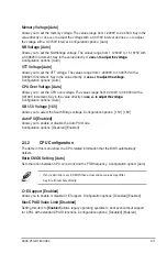
Страница 49: ...ue directly or use to adjust the voltage with a 0 0150V interval and use to adjust the voltage with a 0 0750V interval Configuration options Auto NB Voltage Auto Allows you to set the Northbridge voltage The values range from 1 12500V to 1 51875V with a 0 00625V increment Key in the value directly or use to adjust the voltage Configuration options Auto VTT Voltage Auto Allows you to set the VTT vo...

Страница 50: ...Enhanced Intel SpeedStep Technology EIST Intel R SpeedStep TM Tech Enabled Allows you to use the Enhanced Intel SpeedStep Technology When set to Enabled you can adjust the system power settings in the operating system to use the EIST feature Set this item to Disabled if you do not want to use the EIST Configuration options Enabled Disabled Intel R Virtualization Tech Enabled Enables or disables In...

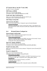
Страница 51: ...A Channel DMA3 Appears only when the Parallel Port Mode is set to ECP This item allows you to set the Parallel Port ECP DMA Configuration options DMA0 DMA1 DMA3 EPP Version 1 9 Appears only when the Parallel Port Mode is set to EPP Configuration options 1 9 1 7 Parallel Port IRQ IRQ7 Allows you to select parallel port IRQ Configuration options IRQ5 IRQ7 GTT Graphics Memory Size No VT mode 2MB This...

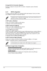
Страница 52: ...rt is disabled Configuration options Disabled Enabled Auto USB 2 0 Controller Mode HiSpeed Allows you to configure the USB 2 0 controller in HiSpeed 480Mbps or Full Speed 12Mbps Configuration options FullSpeed HiSpeed The following items may only appear when a USB storage device is plugged USB Mass Storage Device Configuration USB Mass Storage Reset Delay 20 Sec Allows you to set the maximum time ...

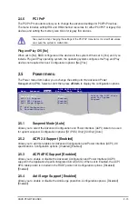
Страница 53: ...u to enable or disable the Advanced Configuration and Power Interface ACPI support in the Application Specific Integrated Circuit ASIC When set to Enabled the ACPI APIC table pointer is included in the RSDT pointer list Configuration options Disabled Enabled 2 5 4 Anti Surge Support Enabled Allows you to enable or disable the Anti Surge protection Configuration options Disabled Enabled Take cautio...

Страница 54: ...board Disabled Allows you to use specific keys on the keyboard to turn on the system This feature requires an ATX power supply that provides at least 1A on the 5VSB lead Configuration options Disabled Space Bar Ctrl Esc Power Key Power On By PS 2 Mouse Disabled When set to Enabled this parameter allows you to use the PS 2 mouse to turn on the system This feature requires an ATX power supply that p...

Страница 55: ...TY Main Advanced Power Boot Tools Exit 2 6 2 Boot Settings Configuration Quick Boot Enabled Enabling this item allows the BIOS to skip some power on self tests POST while booting to decrease the time needed to boot the system When set to Disabled BIOS performs all the POST items Configuration options Disabled Enabled To select the boot device during system startup press F8 when ASUS Logo appears T...

Страница 56: ...visor Password item on top of the screen shows the default Not Installed After you set a password this item shows Installed To set a Supervisor Password 1 Select the Change Supervisor Password item and press Enter 2 In the password box key in a password containing up to six letters or numbers or both then press Enter 3 Confirm the password when prompted The message Password Installed appears after...

Страница 57: ...e user password The User Password item on top of the screen shows the default Not Installed After you set a password this item shows Installed To set a User Password 1 Select the Change User Password item and press Enter 2 In the password box key in a password containing up to six letters or numbers or both then press Enter 3 Confirm the password when prompted The message Password Installed appear...

Страница 58: ...iguration options No Reset When setting this item to Reset ensure to save the setting to the BIOS so that the user data will be cleared the next time you enter the Express Gate User data includes the Express Gate s settings as well as any personal information stored by the web browser bookmarks cookies browsing history etc This is useful in the rare case where corrupt settings prevent the Express ...

Страница 59: ...ion from the Exit menu to ensure the values you selected are saved to the CMOS RAM An onboard backup battery sustains the CMOS RAM so it stays on even when the PC is turned off When you select this option a confirmation window appears Select OK to save changes and exit Exit Discard Changes Select this option only if you do not want to save the changes that you made to the Setup program If you made...

Страница 60: ...2 22 Chapter 2 BIOS information ...

Страница 61: ...510 739 3777 Fax 1 510 608 4555 Web site usa asus com Technical Support Telephone 1 812 282 2787 Support fax 1 812 284 0883 Online support support asus com ASUS Computer GmbH Germany and Austria Address Harkort Str 21 23 D 40880 Ratingen Germany Fax 49 2102 959911 Web site www asus de Online contact www asus de sales Technical Support Telephone Component 49 1805 010923 Telephone System Notebook Ee...

Страница 62: ...N Country GERMANY declare the following apparatus Product name Motherboard Model name P5G41T M USB3 conform with the essential requirements of the following directives 2004 108 EC EMC Directive EN 55022 2006 A1 2007 EN 61000 3 2 2006 EN 55013 2001 A1 2003 A2 2006 EN 55024 1998 A1 2001 A2 2003 EN 61000 3 3 1995 A1 2001 A2 2005 EN 55020 2007 1999 5 EC R TTE Directive EN 300 328 V1 7 1 2006 05 EN 300...

Отзывы: