Asus P4V8X-X Скачать руководство пользователя страница 46

2-12

Chapter 2: BIOS information

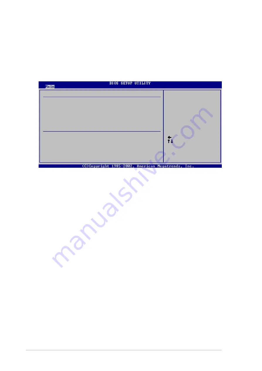
2.3.4 Primary/Secondary/Third/Fourth

IDE Master/Slave

While entering Setup, BIOS auto-detects the presence of IDE devices. There is a
separate sub-menu for each IDE device. Select a device item then press Enter to
display the IDE device information.

The values opposite the dimmed items (Device, Vendor, Size, LBA Mode, Block
Mode, PIO Mode, Async DMA, Ultra DMA, and SMART monitoring) are auto-
detected by BIOS and are not user-configurable. These items show N/A if no IDE
device is installed in the system.

Type [Auto]

Selects the type of IDE drive. Configuration options: [Not Installed] [Auto]
[CDROM] [ARMD]

LBA/Large Mode [Auto]

Enables or disables the LBA mode. Setting to Auto enables the LBA mode if the
device supports this mode, and if the device was not previously formatted with LBA
mode disabled. Configuration options: [Disabled] [Auto]

Block (Multi-sector Transfer) [Auto]

Enables or disables data multi-sectors transfers. When set to Auto, the data
transfer from and to the device occurs multiple sectors at a time if the device
supports multi-sector transfer feature. When set to Disabled, the data transfer from
and to the device occurs one sector at a time. Configuration options: [Disabled]
[Auto]

PIO Mode [Auto]

Selects the PIO mode. Configuration options: [Auto] [0] [1] [2] [3] [4]

Device        : Hard Disk
Vendor        : ST320413A
Size          : 20.0GB
LBA Mode      : Supported
Block Mode    : 16 Sectors
PIO Mode      : 4
Async DMA     : MultiWord DMA-2
Ultra DMA     : Ultra DMA-5
SMART Monitoring: Supported

Select the type
of device connected
to the system.

Primary IDE Master

     Select Screen
     Select Item
+-   Change Option
F1   General Help
F10  Save and Exit
ESC  Exit

Type
LBA/Large Mode
Block (Multi-sector Transfer)
PIO Mode
DMA Mode
Smart Monitoring
32Bit Data Transfer

[Auto]
[Auto]
[Auto]
[Auto]
[Auto]
[Auto]
[Disabled]

Содержание P4V8X-X

Страница 1: ...Motherboard P4V8X X User Guide ...

Страница 2: ...A PARTICULAR PURPOSE IN NO EVENT SHALL ASUS ITS DIRECTORS OFFICERS EMPLOYEES OR AGENTS BE LIABLE FOR ANY INDIRECT SPECIAL INCIDENTAL OR CONSEQUENTIAL DAMAGES INCLUDING DAMAGES FOR LOSS OF PROFITS LOSS OF BUSINESS LOSS OF USE OR DATA INTERRUPTION OF BUSINESS AND THE LIKE EVEN IF ASUS HAS BEEN ADVISED OF THE POSSIBILITY OF SUCH DAMAGES ARISING FROM ANY DEFECT OR ERROR IN THIS MANUAL OR PRODUCT SPECI...

Страница 3: ... 1 8 1 Overview 1 10 1 8 2 Installing the CPU 1 11 1 9 System memory 1 12 1 9 1 Installing a DIMM 1 12 1 9 2 Memory configurations 1 13 1 10 Expansion slots 1 14 1 10 1 Standard interrupt assignments 1 14 1 10 2 IRQ assignments for this motherboard 1 14 1 10 3 PCI slots 1 15 1 10 4 AGP slot 1 15 1 11 Jumper 1 16 1 12 Connectors 1 18 Chapter 2 BIOS information 2 1 Managing and updating your BIOS 2 ...

Страница 4: ... 2 4 Advanced menu 2 14 2 4 1 JumperFree Configuration 2 14 2 4 2 USB Configuration 2 15 2 4 3 CPU Configuration 2 17 2 4 4 Chipset 2 17 2 4 5 Onboard Devices Configuration 2 20 2 4 6 PCI PnP 2 21 2 5 Power menu 2 22 2 5 1 Suspend Mode Auto 2 22 2 5 2 Repost Video on S3 Resume No 2 22 2 5 3 ACPI 2 0 Support No 2 22 2 5 4 ACPI APIC Support Enabled 2 23 2 5 5 APM Configuration 2 23 2 5 6 Hardware Mo...

Страница 5: ...use harmful interference to radio or television reception which can be determined by turning the equipment off and on the user is encouraged to try to correct the interference by one or more of the following measures Reorient or relocate the receiving antenna Increase the separation between the equipment and receiver Connect the equipment to an outlet on a circuit different from that to which the ...

Страница 6: ...your area If you are not sure about the voltage of the electrical outlet you are using contact your local power company If the power supply is broken do not try to fix it by yourself Contact a qualified service technician or your retailer Operation safety Before installing the motherboard and adding devices on it carefully read all the manuals that came with the package Before using the product ma...

Страница 7: ...d software products The ASUS websites are listed in the ASUS Contact Information on page viii 2 Optional Documentation Your product package may include optional documentation such as warranty flyers that may have been added by your dealer These documents are not part of the standard package WARNING Information to prevent injury to yourself when trying to complete a task CAUTION Information to prev...

Страница 8: ... USA Fax 1 510 608 4555 E mail tmd1 asus com Web site usa asus com Technical Support Telephone General 1 502 995 0883 Notebook 1 510 739 3777 Support fax 1 502 933 8713 Support e mail tsd asus com ASUS COMPUTER GmbH Germany and Austria Address Harkort Str 25 D 40880 Ratingen Germany Telephone 49 2102 95990 Fax 49 2102 959911 Online contact www asuscom de sales Technical Support Telephone 49 2102 9...

Страница 9: ...nly 5 x PCI 2 x UltraDMA 133 connectors 2 x Serial ATA connectors with RAID 0 RAID 1 function ADI AD1980 SoundMax 6 channel audio CODEC support for S PDIF out interface Realtek RTL8201BL 10 100 Mbps LAN PHY Maximum of 8 USB 2 0 ports Intelligent CPU frequency tuner ASUS JumperFree CPU and Memory voltage adjustable SFS Stepless Frequency Selection at 1 MHz increment Adjustable FSB DDR ratio ASUS C ...

Страница 10: ...ts CPU Chassis fan connectors 20 pin 4 pin ATX 12V power connectors CD AUX connectors Game MIDI connector 10 1 pin front panel connector 4Mb Flash ROM AMI BIOS ACPI PnP DMI2 0 ASUS EZ Flash ASUS MyLogo2 PCI 2 2 USB 2 0 1 1 DMI 2 0 WOL WOR by PME chassis intrusion ATX power supply with 4 pin 12V plug Device drivers ASUS PC Probe ASUS LiveUpdate Trend Micro PC cillin 2002 anti virus software ATX for...

Страница 11: ...1 This chapter describes the features of the P4V8X X motherboard It includes brief descriptions of the motherboard components and illustrations of the layout jumper settings and connectors Product introduction ...

Страница 12: ...ordable vehicle to enter the world of computing Before you start installing the motherboard and hardware devices on it check the items in your package with the list below 1 2 Package contents Check your P4V8X X package for the following items 1 3 Special features Latest processor technology The motherboard supports the Intel Pentium 4 processor with 512KB L2 cache and an 800 533 400 MHz system bus...

Страница 13: ...GP8X AGP 3 0 is the next generation VGA interface specification that enables enhanced graphics performance with high bandwidth up to 2 12GB s See pages 1 15 USB 2 0 technology The motherboard implements the new Universal Serial Bus USB 2 0 specification extending the connection speed from 12 Mbps on USB 1 1 to a fast 480 Mbps on USB 2 0 See pages 1 6 and 1 21 6 channel digital audio The ADI 1980 A...

Страница 14: ...e you install the motherboard learn about its major components and available features to facilitate the installation and future upgrades Refer to the succeeding pages for the component descriptions 4 3 2 5 6 13 1 7 9 11 10 16 8 15 14 12 17 27 24 20 21 22 23 18 19 25 26 ...

Страница 15: ...elerated Graphics Port AGP slot supports 1 5V 0 8V AGP 8X 4X mode graphics cards for 3D graphical applications SATA connectors These connectors support Serial ATA HDDs and allow up to 150MB s data transfer rate using thin 4 conductor SATA cables South bridge controller The VIA VT8237 integrated peripheral controller supports various I O functions including two Serial ATA ports 2 channel ATA 133 bu...

Страница 16: ... 25 pin port connects a parallel printer a scanner or other devices RJ 45 port This port allows connection to a Local Area Network LAN through a network hub Line In jack This Line In light blue jack connects a tape player or other audio sources In 6 channel mode the function of this jack becomes Bass Center Line Out jack This Line Out lime jack connects a headphone or a speaker In 6 channel mode t...

Страница 17: ...dule CHA_FAN1 VIA VT8237 Chipset USB78 SB_PWR1 USBPW78 19 3cm 7 6in 30 5cm 12 0in DDR DIMM2 64 72 bit 184 pin module DDR DIMM3 64 72 bit 184 pin module RJ 45 Top USB3 USB4 Bottom USB12 PS 2KBMS T Mouse B Keyboard SPDIF1 PARALLEL PORT COM1 PCI2 PCI3 PCI4 PCI5 FLOPPY VIA P4X533 Chip ATX12V1 CR2032 3V Lithium Cell CMOS Power Socket 478 USB56 Below Mic In Center Line Out Top Line In SATA1 SATA2 10 100...

Страница 18: ...d from the wall socket before touching any component 2 Use a grounded wrist strap or touch a safely grounded object or to a metal object such as the power supply case before handling components to avoid damaging them due to static electricity 3 Hold components by the edges to avoid touching the ICs on them 4 Whenever you uninstall any component place it on a grounded antistatic pad or in the bag t...

Страница 19: ... you place it into the chassis in the correct orientation The edge with external ports goes to the rear part of the chassis as indicated in the image below 1 7 2 Screw holes Place seven 7 screws into the holes indicated by circles to secure the motherboard to the chassis Place this side towards the rear of the chassis Do not overtighten the screws Doing so may damage the motherboard Make sure to u...

Страница 20: ...ding Technology 1 This motherboard supports Intel Pentium 4 CPUs with Hyper Threading Technology 2 Hyper Threading Technology is supported under Windows XP and later versions only 3 It is recommended that you install WinXP Service Pack 1 4 For more information on Hyper Threading Technology visit www intel com info hyperthreading P4V8X X P4V8X X Socket 478 Gold Arrow If the system becomes unstable ...

Страница 21: ...its in place 5 When the CPU is in place push down the socket lever to secure the CPU The lever clicks on the side tab to indicate that it is locked Socket Lever 90 100 Gold Mark 6 Install a CPU heatsink and fan following the instructions that came with the heatsink package 7 Connect the CPU fan cable to the CPU_FAN1 connector on the motherboard The CPU fits only in one correct orientation DO NOT f...

Страница 22: ...socket by pressing the retaining clips outward 2 Align a DIMM on the socket such that the notch on the DIMM matches the break on the socket 3 Firmly insert the DIMM into the socket until the retaining clips snap back in place and the DIMM is properly seated Unlocked Retaining Clip DDR DIMM notch 1 9 1 Installing a DIMM Make sure to unplug the power supply before adding or removing DIMMs or other s...

Страница 23: ...0X64C3A 256 KINGSTON SS HY5DU56822BT D43 512MB KINGSTON KVR400X64C3A 512 KINGSTON DS HY5DU56822BT D43 256MB Winbond W9425GCDB 5 Winbond SS W942508CH 5 512MB Infineon HYS64D64320GU 5 B Infineon DS HYB25D256800BT 5B 256MB SAMSUNG M368L3223ETM CCC SAMSUNG SS K4H560838E TCCC 256MB Hynix HYMD232646B8J D43 AA Hynix SS HY5DU56822BT D43 512MB Hynix HYMD264646B8J D43 AA Hynix DS HY5DU56822BT D43 512MB PSC ...

Страница 24: ...em Timer 1 2 Keyboard Controller 2 N A Programmable Interrupt 3 11 Communications Port COM2 4 12 Communications Port COM1 5 13 Sound card sometimes LPT2 6 14 Floppy Disk Controller 7 15 Printer Port LPT1 8 3 System CMOS Real Time Clock 9 4 ACPI Mode when used 10 5 IRQ Holder for PCI Steering 11 6 IRQ Holder for PCI Steering 12 7 PS 2 Compatible Mouse Port 13 8 Numeric Data Processor 14 9 Primary I...

Страница 25: ...cations 1 10 4 AGP slot This motherboard has an Accelerated Graphics Port AGP slot that supports AGP 8X 4X cards When you buy an AGP card make sure that you ask for one with 1 5V or 0 8V specification Note the notches on the card golden fingers to ensure that they fit the AGP slot on your motherboard This motherboard does not support 3 3V AGP cards P4V8X X P4V8X X Accelerated Graphics Port AGP Key...

Страница 26: ...cell battery To erase the RTC RAM 1 Turn OFF the computer and unplug the power cord 2 Move the jumper cap from pins 1 2 default to pins 2 3 Keep the cap on pins 2 3 for about 5 10 seconds then move the cap back to pins 1 2 3 Plug the power cord and turn ON the computer 4 Hold down the Del key during the boot process and enter BIOS setup to re enter data Except when clearing the RTC RAM never remov...

Страница 27: ...2 5V by default because not all computers have the appropriate power supply to support this feature The USBPW12 and USBPW34 jumpers are for the rear USB ports The USBPW56 and USBPW78 jumpers are for the internal USB header that you can connect to the front USB ports 1 This feature requires a power supply that can provide 500mA on the 5VSB lead for each USB port 2 The total current consumed must NO...

Страница 28: ...ng ribbon cables with pin 5 plug 2 Serial ATA connectors 7 pin SATA1 SATA2 These next generation connectors support the thin Serial ATA cables for Serial ATA hard disks The current Serial ATA interface allows up to 150 MB s data transfer rate faster than the standard parallel ATA with 133 MB s Ultra ATA 133 P4V8X X NOTE Orient the red markings on the floppy ribbon cable to PIN 1 P4V8X X Floppy Dis...

Страница 29: ...efer to the hard disk documentation for the jumper settings BIOS supports specific device bootup If you have more than two UltraDMA100 66 33 devices purchase another UltraDMA100 66 33 cable You may configure two hard disks to be both master devices with two ribbon cables one for the primary IDE connector and another for the secondary IDE connector 1 Pin 20 on each IDE connector is removed to match...

Страница 30: ...at the black wire of each cable matches the ground pin of the connector Do not forget to connect the fan cables to the fan connectors Lack of sufficient air flow within the system may damage the motherboard components These are not jumpers DO NOT place jumper caps on the fan connectors Make sure that your ATX 12V power supply can provide 8A on the 12V lead and at least 1A on the 5 volt standby lea...

Страница 31: ...ader The module has two USB 2 0 ports that support the next generation USB peripherals such as high resolution cameras scanners and printers 6 Internal audio connectors 4 pin CD1 AUX1 These connectors allow you to receive stereo audio input from sound sources such as a CD ROM TV tuner or MPEG card The USB2 0 GAME module is purchased separately You must install the driver before you can use the USB...

Страница 32: ...laying or editing audio files 9 Front panel audio connector 10 1 pin FP_AUDIO1 This is an interface for the Intel front panel audio cable that allow convenient connection and control of audio devices The USB GAME module is purchased separately P4V8X X P4V8X X Game Connector GAME1 5V 5V J2B1 J2CX MIDI_OUT J2CY J2B2 MIDI_IN J1B1 J1CX GND GND J1CY J1B2 5V P4V8X X P4V8X X Front Panel Audio Connector F...

Страница 33: ...he pins 11 System panel connector 20 pin PANEL1 This connector accommodates several system front panel functions System Power LED Lead 3 1 pin PLED This 3 1 pin connector connects to the system power LED The LED lights up when you turn on the system power and blinks when the system is in sleep mode System Warning Speaker Lead 4 pin SPKR This 4 pin connector connects to the case mounted speaker and...

Страница 34: ... Pressing the power switch while in the ON mode for more than 4 seconds turns the system OFF System Management Interrupt Lead 2 pin SMI This 2 pin connector allows you to manually place the system into a suspend mode or green mode where system activity is instantly decreased to save power and to expand the life of certain system components Attach the case mounted suspend switch to this 2 pin conne...

Страница 35: ...Chapter 2 This chapter tells how to change system settings through the BIOS Setup menus Detailed descriptions of the BIOS parameters are also provided BIOS information ...

Страница 36: ... a 1 44 MB floppy disk into the drive At the DOS prompt type format A S Enter Windows environment a From your Windows desktop click on Start point to Settings then click on Control Panel b Double click on Add Remove Programs icon from the Control Panel window c Click on the Startup Disk tab then on Create Disk button d Insert a 1 44 MB floppy disk when prompted Follow the succeeding screen instruc...

Страница 37: ...asing flash done Writing flash 0x0008CC00 9 When the BIOS update process is complete the utility returns to the DOS prompt A afudos ip4v8xx rom AMI Firmware Update Utility Version 1 10 Copyright C 2002 American Megatrends Inc All rights reserved Reading file done Erasing flash done Writing flash 0x0008CC00 9 Verifying flash done A 5 Reboot the system from the hard disk The BIOS information on the ...

Страница 38: ... PC The AFUDOS EXE utility can also be used to copy the current system BIOS settings to a floppy or hard disk The copy can be used as a backup in case the system BIOS fails or gets corrupted When the BIOS copy process is complete the utility returns to the DOS prompt Main filename Extension name A afudos oMYBIOS03 rom AMI Firmware Update Utility Version 1 10 Copyright C 2002 American Megatrends In...

Страница 39: ...tem 3 To launch EZ Flash press Alt F2 during POST to display the following 4 Insert the floppy disk that contains the BIOS file If the P4V8XX ROM file is found in the floppy disk EZ Flash performs the BIOS update process and automatically reboots the system when done User recovery requested Starting BIOS recovery Checking for floppy Floppy found Reading file p4v8xx rom Completed Start flashing Fla...

Страница 40: ...ction 2 1 1 Creating a bootable floppy disk To recover the BIOS from a floppy disk 1 Boot the system 2 When a corrupted BIOS is detected the following message appears Bad BIOS checksum Starting BIOS recovery Checking for floppy 3 Insert a floppy disk that contains the original or the latest BIOS file for this motherboard P4V8XX ROM If the BIOS file that you downloaded from the ASUS website has a d...

Страница 41: ...ed BIOS is detected the following screen message appears Bad BIOS checksum Starting BIOS recovery Checking for floppy 3 Place the support CD in the CD ROM The support CD contains the original BIOS for this motherboard DO NOT shutdown or reset the system while updating the BIOS Doing so may cause system boot failure 4 When the BIOS update process is complete reboot the system Bad BIOS checksum Star...

Страница 42: ...puter the system provides you with the opportunity to run this program Press Delete during the Power On Self Test POST to enter the Setup utility Otherwise POST continues with its test routines If you wish to enter Setup after POST restart the system by pressing Ctrl Alt Delete or by pressing the reset button on the system chassis You can also restart by turning the system off and then back on Do ...

Страница 43: ...2 3 Navigation keys At the bottom right corner of a menu screen are the navigation keys for that particular menu Use the navigation keys to select items in the menu and change the settings System Time 11 10 19 System Date Thu 05 27 2003 Legacy Diskette A 1 44M 3 5 in Primary IDE Master ST320413A Primary IDE Slave ASUS CD S340 Secondary IDE Master Not Detected Secondary IDE Slave Not Detected Syste...

Страница 44: ... on the screen Press Up Down arrow keys or PageUp PageDown keys to display the other items on the screen 2 2 9 General help At the top right corner of the menu screen is a brief description of the selected item System Time 11 10 19 System Date Thu 05 27 2003 Legacy Diskette A 1 44M 3 5 in Primary IDE Master ST320413A Primary IDE Slave ASUS CD S340 Secondary IDE Master Not Detected Secondary IDE Sl...

Страница 45: ...ration options Disabled 360K 5 25 in 1 2M 5 25 in 720K 3 5 in 1 44M 3 5 in 2 88M 3 5 in System Time 11 10 19 System Date Thu 05 27 2003 Legacy Diskette A 1 44M 3 5 in Primary IDE Master ST320413A Primary IDE Slave ASUS CD S340 Secondary IDE Master Not Detected Secondary IDE Slave Not Detected System Information Use ENTER TAB or SHIFT TAB to select a field Use or to configure system time Select Scr...

Страница 46: ...eviously formatted with LBA mode disabled Configuration options Disabled Auto Block Multi sector Transfer Auto Enables or disables data multi sectors transfers When set to Auto the data transfer from and to the device occurs multiple sectors at a time if the device supports multi sector transfer feature When set to Disabled the data transfer from and to the device occurs one sector at a time Confi...

Страница 47: ...cted by BIOS AMI BIOS This item displays the auto detected BIOS information Processor This item displays the auto detected CPU specification System Memory This item displays the auto detected system memory DMA Mode Auto Selects the DMA mode Configuration options Auto SWDMA0 SWDMA1 SWDMA2 MWDMA0 MWDMA1 MWDMA2 UDMA0 UDMA1 UDMA2 UDMA3 UDMA4 UDMA5 UDMA6 SMART Monitoring Auto Sets the Smart Monitoring ...

Страница 48: ... Exit CPU Compatible Mode Disabled AI Overclock Tuner Standard CPU Reference Voltage Auto DDR Reference Voltage Auto Configure System Frequency Voltage If your system becomes unstable when using an 800MHz FSB CPU enable this item to lower the FSB frequency by 10 Take caution when changing the settings of the Advanced menu items Incorrect field values may cause the system to malfunction CPU Compati...

Страница 49: ...to detected by BIOS and is not manually configurable The values range from 100 to 400 Press the or key to adjust the CPU frequency This item does not appear when the CPU Compatible Mode item is enabled CPU Reference Voltage Auto Allows selection of the Central Processing Unit CPU operating voltage Configuration options Auto Over Voltage DDR Reference Voltage Auto Allows selection of the DDR SDRAM ...

Страница 50: ...Set to Full Speed for 12Mbps of transfer speed Configuration options Hi Speed Full Speed Select Screen Select Item Change Option F1 General Help F10 Save and Exit ESC Exit USB Mass Storage Reset Delay 20 Sec No USB Mass Storage device detected Device 1 N A Emulation Type N A Device 2 N A Emulation Type N A Device 3 N A Emulation Type N A Device 4 N A Emulation Type N A Device 5 N A Emulation Type ...

Страница 51: ...CPU related information auto detected by BIOS Select Screen Select Item Change Option F1 General Help F10 Save and Exit ESC Exit Manufacturer Intel R Brand String Intel R Pentium R 4 CPU 1500MHz Frequency 1500MHz Ratio Status Locked Ratio Actual Value 18 Configure advanced CPU settings Emulation Type N A When set to Auto USB devices less than 530MB will be emulated as floppy drive and the remainin...

Страница 52: ... 2 0T 2 5T 3 0T SDRAM Bank Interleave Disabled This item controls the latency between the SDRAM read command and the time the data actually becomes available Configuration options Disabled 2 Way 4 Way NorthBridge VIA P4X533 Configuration Select Screen Select Item Change Option F1 General Help F10 Save and Exit ESC Exit DRAM Timing Configure SDRAM Timing by SPD Enabled SDRAM Frequency Auto SDRAM Bu...

Страница 53: ...reen Select Item Change Option F1 General Help F10 Save and Exit ESC Exit MPS Revision 1 1 PCI Delay Transaction Disabled OnBoard LAN Enabled OnBoard LAN Boot ROM Disabled OnBoard AC 97 Audio Enabled MPS Revision 1 1 Configuration options 1 1 1 4 PCI Delay Transaction Enabled This item enables or disables the PCI Delay Transaction feature Configuration options Disabled Enabled OnBoard LAN Enabled ...

Страница 54: ...ion options Disabled 378 278 3BC Parallel Port Mode ECP Allows you to select the Parallel Port mode Configuration options Normal Bi directional EPP ECP ECP Mode DMA Channel DMA3 Allows selection of the Parallel Port ECP DMA channel This item appears only when the Parallel Port Mode is set to ECP Configuration options DMA0 DMA1 DMA3 Parallel Port IRQ IRQ7 Allows you to select the Parallel Port IRQ ...

Страница 55: ...ystem has a Plug and Play operating system Plug and Play O S No When set to No BIOS configures all the devices in the system When set to Yes and if you installed a Plug Play operating system the operating system configures the Plug Play devices not required for boot Configuration options No Yes PCI Latency Timer 64 Allows you to select the value in units of PCI clocks for the PCI device latency ti...

Страница 56: ...ss Enter to display the configuration options Suspend Mode S1 POS S3 STR Repost Video on S3 Resume No ACPI 2 0 Support No ACPI APIC Support Enabled APM Configuration Hardware Monitor Configure CPU Select Screen Select Item Enter Go to Sub screen F1 General Help F10 Save and Exit ESC Exit 2 5 1 Suspend Mode S1 POS S3 STR Auto Allows you to select the ACPI state to be used for system suspend Configu...

Страница 57: ...lowing items appears only if the Power Management APM item is set to Enabled 2 5 4 ACPI APIC Support Enabled Allows you to enable or disable the ACPI support in the APIC When set to Enabled the ACPI APIC table pointer is included in the RSDT pointer list Configuration options Disabled Enabled Video Power Down Mode Suspend Allows you to select the video power down mode Configuration options Disable...

Страница 58: ...u to enable or disable RTC to generate a wake event When this item is set to Enabled the items RTC Alarm Date RTC Alarm Hour RTC Alarm Minute and RTC Alarm Second appear with set values Configuration options Disabled Enabled Power On by PS 2 Mouse Disabled When set to Enabled this parameter allows you to use the PS 2 mouse to resume the system This feature requires an ATX power supply that provide...

Страница 59: ...oard and CPU temperatures CPU Fan Speed xxxxRPM or N A Chassis Fan Speed xxxxRPM or N A The onboard hardware monitor automatically detects and displays the CPU and chassis fan speeds in rotations per minute RPM If any of the fans is not connected to the motherboard the specific field shows N A CPU Reference Voltage 3 3V Voltage 5V Voltage 12V Voltage The onboard hardware monitor automatically dete...

Страница 60: ...tion F1 General Help F10 Save and Exit ESC Exit 1st Boot Device First Floppy Drive 2nd Boot Device PM ST320413A Boot Device Priority Specifies the boot sequence from the available devices A device enclosed in parenthesis has been disabled in the corresponding type menu 1st xxth Boot Device 1st Floppy Drive These items specify the boot device priority sequence from the available devices The number ...

Страница 61: ...ons Disabled Enabled Full Screen Logo Enabled Setting to Disabled displays the normal POST messages Setting to Enabled displays the OEM logo instead of the POST messages Users can use ASUS MyLogo2 to change the default logo Configuration options Disabled Enabled Add On ROM Display Mode Force BIOS Sets the display mode for option ROM Configuration options Force BIOS Keep Current Bootup Num Lock On ...

Страница 62: ...After you have set a password this item shows Installed To set a Supervisor Password 1 Select the Change Supervisor Password item and press Enter 2 On the password box that appears type a password composed of letters and or numbers then press Enter Your password should have at least six characters 3 Confirm the password when prompted The message Password Installed appears after you have successful...

Страница 63: ...e password box that appears type a password composed of letters and or numbers then press Enter Your password should have at least six characters 3 Confirm the password when prompted The message Password Installed appears after you have successfully set your password The User Password item now shows Installed To change the user password follow the same steps as in setting a user password Clear Use...

Страница 64: ...o save the changes that you made to the Setup program If you made changes to fields other than system date system time and password the BIOS asks for a confirmation before exiting Discard Changes This option allows you to discard the selections you made and restore the previously saved values After selecting this option a confirmation appears Select Yes to discard any changes and load the previous...

Страница 65: ...Chapter 3 This chapter describes the contents of the support CD that comes with the motherboard package Software support ...

Страница 66: ...simply insert the CD into your CD ROM drive The CD automatically displays the Drivers menu if Autorun is enabled in your computer Click an icon to display more information Click an item to install Because motherboard settings and hardware options vary use the setup procedures presented in this chapter for general reference only Refer to your OS documentation for more information The contents of th...

Страница 67: ...river This item installs the ADI 1980 AC 97 compliant audio controller and application VIA RAID Controller driver This item installs the VIA RAID controller driver and application to configure and manage disk drives VIA 10 100Mb LAN Driver This item installs the VIA 10 100Mbps Fast Ethernet driver to support 10 100 Mbps networking USB 2 0 Driver This item installs the USB 2 0 driver 3 2 3 Utilitie...

Страница 68: ...ernet connection so you can connect to the ASUS website Installing ASUS Update also installs ASUS Mylogo2 PC CILLIN 2002 This item installs the PC cillin 2002 anti virus program View the PC cillin online help for detailed information Adobe Acrobat Reader This item installs the Adobe Acrobat Reader V5 0 The Acrobat Reader software is for viewing files saved in Portable Document Format PDF ASUS Scre...

Страница 69: ...u are creating a RAID 0 striping array for perfomance use two new drives If you are creating a RAID 1 mirroring array for protection you can use two new drives or use an existing drive and a new drive the new drive must be of the same size or larger than the existing drive If you use two drives of different sizes the smaller capacity hard disk will be the base storage size For example one hard dis...

Страница 70: ...llowing menu options will appear Channel Drive Name Array Name Mode Size GB Status Serial_Ch0 Master XXXXXXXXXX xxxxx xxx xx Hdd Serial_Ch1 Master XXXXXXXXXX xxxxx xxx xx Hdd VIA Tech RAID BIOS Ver 1 XX Create Array Delete Array Create Delete Spare Select Boot Array Serial Number View Create a RAID array with the hard disk attached to VIA IDE controller F1 View Array Disk Status Move to next item ...

Страница 71: ...SC Exit 3 3 3 1 RAID 0 for performance 1 Select the second option Array Mode then press the Enter key to display the RAID system setting pop up menu 2 Select RAID 0 for performance from the menu and press Enter From this point you may choose to auto configure the RAID array by selecting Auto Setup for Performance or manually configure the RAID array for stripped sets If you want to manually config...

Страница 72: ...ta on the selected disks will be destroyed Continue Press Y N 4K 8K 16K 32K 64K RAID 0 for performance RAID 1 for data protection RAID 0 1 RAID SPAN for capacity RAID 1 for data protection Create only Create and duplicate Create only 3 Select task and press Enter The screen returns to Create Array menu items From this point you may choose to auto configure the RAID array by selecting Auto Setup fo...

Страница 73: ...Enter key The focus is directed to the list of channel used for IDE RAID arrays 2 Press the Enter key to select a RAID array to delete The following confirmation message appears Press Y to confirm or N to return to the configuration options The selected array will be destroyed Are you sure Continue Press Y N 4 Select Start Create Process and press Enter to setup hard disk for RAID system The follo...

Страница 74: ...reate Delete Spare Select Boot Array Serial Number View Create a RAID array with the hard disk attached to VIA IDE controller F1 View Array Disk Status Move to next item Enter Confirme the selection ESC Exit Serial Number xxxxxxxx 3 3 5 Select Boot Array 1 In the VIA RAID BIOS utility main menu select Select Boot Array then press the Enter key The focus is directed to the list of channel used for ...

Отзывы: