background image

2-18

Chapter 2: BIOS information

CPU Level 1 Cache, CPU Level 2 Cache [Enabled]

These fields allow you to choose from the default [Enabled] or choose [Disabled] to
turn on or off the CPU Level 1 and Level 2 built-in cache. Configuration options:
[Disabled] [Enabled]

BIOS Update [Enabled]

This field functions as an update loader integrated into the BIOS to supply the
processor with the required data. When set to [Enabled], the BIOS loads the
update on all processors during system bootup. Configuration options: [Disabled]
[Enabled]

PS/2 Mouse Function Control [Auto]

The default setting [Auto] allows the system to detect a PS/2 mouse at startup. If a
mouse is detected, the BIOS assigns IRQ12 to the PS/2 mouse. Otherwise, IRQ12
can be used for expansion cards. When you set this field to [Enabled], BIOS
reserves IRQ12, whether or not a PS/2 mouse is detected at startup. Configuration
options: [Enabled] [Auto]

USB Legacy Support [Auto]

This motherboard supports Universal Serial Bus (USB) devices. The default of
[Auto] allows the system to detect a USB device at startup. If detected, the USB
controller legacy mode is enabled. If not detected, the USB controller legacy mode
is disabled.

When you set this field to [Disabled], the USB controller legacy mode is disabled
whether or not you are using a USB device. Configuration options: [Disabled]
[Enabled] [Auto]

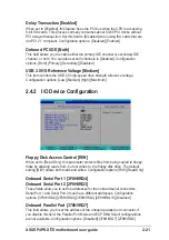
OS/2 Onboard Memory > 64M [Disabled]

When using OS/2 operating systems with installed DRAM of greater than 64MB,
you need to set this option to [Enabled]. Otherwise, leave to the default setting
[Disabled]. Configuration options: [Disabled] [Enabled]

Содержание P4PE-X TE

Страница 1: ...Motherboard P4PE X TE User Guide ...

Страница 2: ...ARTICULAR PURPOSE IN NO EVENT SHALL ASUS ITS DIRECTORS OFFICERS EMPLOYEES OR AGENTS BE LIABLE FOR ANY INDIRECT SPECIAL INCIDENTAL OR CONSEQUENTIAL DAMAGES INCLUDING DAMAGES FOR LOSS OF PROFITS LOSS OF BUSINESS LOSS OF USE OR DATA INTERRUPTION OF BUSINESS AND THE LIKE EVEN IF ASUS HAS BEEN ADVISED OF THE POSSIBILITY OF SUCH DAMAGES ARISING FROM ANY DEFECT OR ERROR IN THIS MANUAL OR PRODUCT SPECIFIC...

Страница 3: ...acement direction 1 9 1 7 2 Screw holes 1 9 1 7 Motherboard installation 1 9 1 8 Central Processing Unit CPU 1 10 1 8 1 Overview 1 10 1 8 2 Installing the CPU 1 11 1 9 System memory 1 12 1 9 1 Memory configurations 1 12 1 9 2 Installing a DIMM 1 13 1 10 Expansion slots 1 14 1 10 1 Standard interrupt assignments 1 14 1 10 2 IRQ assignments for this motherboard 1 14 1 11 Jumpers 1 15 1 12 Connectors...

Страница 4: ...atures 2 15 2 4 Advanced Menu 2 16 2 4 1 Chip Configuration 2 19 2 4 2 I O Device Configuration 2 21 2 4 3 PCI Configuration 2 22 2 5 Power Menu 2 24 2 5 1 Power Up Control 2 26 2 5 2 Hardware Monitor 2 28 2 6 Boot Menu 2 29 2 7 Exit Menu 2 31 Chapter 3 Software support 3 1 3 1 Install an operating system 3 2 3 2 Support CD information 3 2 3 2 1 Running the support CD 3 2 3 2 2 Drivers menu 3 3 3 ...

Страница 5: ...use harmful interference to radio or television reception which can be determined by turning the equipment off and on the user is encouraged to try to correct the interference by one or more of the following measures Reorient or relocate the receiving antenna Increase the separation between the equipment and receiver Connect the equipment to an outlet on a circuit different from that to which the ...

Страница 6: ...your area If you are not sure about the voltage of the electrical outlet you are using contact your local power company If the power supply is broken do not try to fix it by yourself Contact a qualified service technician or your retailer Operation safety Before installing the motherboard and adding devices on it carefully read all the manuals that came with the package Before using the product ma...

Страница 7: ...d software products The ASUS websites are listed in the ASUS Contact Information on page viii 2 Optional Documentation Your product package may include optional documentation such as warranty flyers that may have been added by your dealer These documents are not part of the standard package WARNING Information to prevent injury to yourself when trying to complete a task CAUTION Information to prev...

Страница 8: ... asus com Web Site usa asus com Technical Support Support Fax 1 502 933 8713 General Support 1 502 995 0883 Notebook Support 1 510 739 3777 x5110 Support Email tsd asus com ASUS COMPUTER GmbH Germany and Austria Address Harkortstr 25 40880 Ratingen BRD Germany General Email sales asuscom de for marketing requests only General Fax 49 2102 9599 31 Web Site www asuscom de Technical Support Components...

Страница 9: ...btain PC3200 DDR DIMMs only from ASUS qualified vendors 1 x AGP 4X 1 5V only 6 x PCI 2 x UltraDMA100 66 33 connectors ADI AD1888 6 channel audio CODEC Realtek RTL8100C Fast Ethernet controller ASUS JumperFree mode ASUS EZ Flash ASUS CrashFree BIOS2 ASUS CPU Parameter Recall C P R USB 2 0 ready Power Loss Restart SFS Stepless Frequency Selection CPU throttle Adjustable CPU Vcore 1 x Parallel port 2...

Страница 10: ...or Support CD contents 2Mb Flash ROM Award BIOS TCAV PnP DMI2 0 SM BIOS2 3 ASUS C P R ASUS EZ Flash ASUS CrashFree BIOS2 PCI 2 2 USB 2 0 WfM 2 0 DMI 2 0 WOL WOR by PME chassis intrusion SMBus ATX form factor 12 in x 9 0 in 30 5 cm x 22 9 cm Device drivers ASUS PC Probe ASUS LiveUpdate Trend Micro PC cillin 2002 anti virus software OEM version ...

Страница 11: ... This chapter describes the features of the P4PE X TE motherboard It includes brief descriptions of the motherboard components and illustrations of the layout jumper settings and connectors Product introduction ...

Страница 12: ...e P4PE X TE is your affordable vehicle to enter the world of computing Before you start installing the motherboard and hardware devices on it check the items in your package with the list below Overclocking mode 1 2 Package contents Check your P4PE X TE package for the following items ASUS P4PE X TE motherboard ATX form factor 12 in x 9 in 30 5 cm x 22 9 cm ASUS P4PE X TE series support CD 1 x 80 ...

Страница 13: ...gital Interface S PDIF Out module See page 1 18 Extreme Overclocking The P4PE X TE offers robust overclocking options to maximize your system performance Overclocking features include a flexible CPU core voltage adjustment in 0 025V increments over defaults the SFS Stepless Frequency Selection feature an adjustable FSB DDR ratio with a fixed AGP PCI frequency and the ASUS C P R CPU Parameter Recal...

Страница 14: ...re you install the motherboard learn about its major components and available features to facilitate the installation and future upgrades Refer to the succeeding pages for the component descriptions 17 18 26 25 24 23 20 21 22 19 3 4 1 5 6 10 9 13 2 7 11 12 14 15 16 8 ...

Страница 15: ...aster IDE connectors support Ultra DMA100 66 PIO Modes 3 4 IDE devices Both the primary blue and secondary black connectors are slotted to prevent incorrect insertion of the IDE ribbon cable South bridge controller The fourth generation Intel I O Controller Hub ICH4 is a subsystem that integrates various I O functions including 2 channel ATA100 bus master IDE controller up to six USB 2 0 1 1 ports...

Страница 16: ... of this jack becomes Bass Center Line Out jack This Line Out lime jack connects a headphone or a speaker In 6 channel mode the function of this jack becomes Front Speaker Out Microphone jack This Mic pink jack connects a microphone In 6 channel mode the function of this jack becomes Rear Speaker Out 14 15 16 17 18 19 20 22 21 23 24 25 26 The functions of the Line Out Line In and Microphone jacks ...

Страница 17: ...cs Port AGP GAME1 CLRTC SPDIF1 KBPWR1 CHASSIS1 USB_56 Super I O 2Mbit Firmware Hub ASUS ASIC with Hardware Monitor DDR DIMM1 64 72 bit 184 pin module 0 1 PS 2KBMS T Mouse B Keyboard DDR DIMM2 64 72 bit 184 pin module 2 3 DDR DIMM3 64 72 bit 184 pin module 4 5 Below Mic In Center Line Out Top Line In CPU_FAN1 SEC_IDE CHA_FAN1 PCI2 PCI3 PCI4 PCI5 PCI6 CR2032 3V Lithium Cell CMOS Power ATX Power Conn...

Страница 18: ...uching the ICs on them 4 Whenever you uninstall any component place it on a grounded antistatic pad or in the bag that came with the component 5 Before you install or remove any component ensure that the ATX power supply is switched off or the power cord is detached from the power supply Failure to do so may cause severe damage to the motherboard peripherals and or components When lit the standby ...

Страница 19: ... 7 1 Placement direction When installing the motherboard make sure that you place it into the chassis in the correct orientation The edge with external ports goes to the rear part of the chassis as indicated in the image below 1 7 2 Screw holes Place seven 7 screws into the holes indicated by circles to secure the motherboard to the chassis Make sure to unplug the power cord before installing or r...

Страница 20: ...rnel and later versions only Under Linux use the Hyper Threading compliler to compile the code If you are using any other operating systems disable the Hyper Threading Techonology item in BIOS to ensure system stability and performance 2 It is recommended that you install WinXP Service Pack 1 3 Make sure to enable the Hyper Threading Technology item in BIOS before installing a supported operating ...

Страница 21: ...l it fits in place The CPU fits only in one correct orientation DO NOT force the CPU into the socket to prevent bending the pins and damaging the CPU 5 When the CPU is in place push down the socket lever to secure the CPU The lever clicks on the side tab to indicate that it is locked Socket Lever 90 100 Gold Mark 6 Install a CPU heatsink and fan following the instructions that came with the heatsi...

Страница 22: ...stall a double sided DIMM into DIMM2 socket you must leave DIMM3 socket empty 2 x16 Double sided DDR DIMMs 16 bit memory chips are not supported on this motherboard 3 You may install single sided DIMMs into DIMM2 and DIMM3 sockets at the same time but neither one can be x16 DDR module 1 Use only the following combinations to install DDR DIMMs Otherwise the system may not boot up 2 It is recommende...

Страница 23: ...ling a DIMM Obtain DDR DIMMs only from ASUS qualified vendors to ensure system stability Visit the ASUS website www asus com for the latest qualified vendors list QVL CPU FSB DDR DIMM Type Memory Frequency 800 MHz PC3200 400 MHz 533 MHz PC2700 PC2100 333 266 MHz 400 MHz PC2100 PC1600 266 200 MHz PC3200 Qualified Vendor List QVL Refer to the following Qualified Vendor List QVL before installing PC3...

Страница 24: ...ns Port COM1 5 13 IRQ holder for PCI steering 6 14 Floppy Disk Controller 7 15 Printer Port LPT1 8 3 System CMOS Real Time Clock 9 4 IRQ holder for PCI steering 10 5 Advance AC 97 CODEC 11 6 Standard PCI Graphics Adapter VGA 12 7 PS 2 Compatible Mouse Port 13 8 Numeric Data Processor 14 9 Primary IDE Channel 15 10 Secondary IDE Channel These IRQs are usually available for ISA or PCI devices 1 10 2...

Страница 25: ...ime Clock RTC RAM in CMOS You can clear the CMOS memory of date time and system setup information by erasing the CMOS RTC RAM data To erase the RTC RAM 1 Turn OFF the computer and unplug the power cord 2 Move the jumper cap from pins 1 2 default to pins 2 3 Keep the cap on pins 2 3 for about 5 10 seconds then move the cap back to pins 1 2 3 Plug the power cord and turn ON the computer 4 Hold down ...

Страница 26: ...low power mode using the connected USB devices Set to 5VSB to wake up from S3 sleep mode no power to CPU DRAM in slow refresh power supply in reduced power mode Both jumpers are set to pins 1 2 5V by default because not all computers have the appropriate power supply to support this feature The USBPW12 and USBPW34 jumpers are for the rear USB ports The USBPW56 jumper is for the internal USB header...

Страница 27: ...al and Ground are shorted with a jumper cap If you wish to use the chassis intrusion detection feature remove the jumper cap from the pins P4PE X TE P4PE X TE Chassis Alarm Lead CHASSIS1 5VSB_MB Chassis Signal GND Default P4PE X TE NOTE Orient the red markings on the floppy ribbon cable to PIN 1 P4PE X TE Floppy Disk Drive Connector PIN 1 FLOPPY1 3 Floppy disk drive connector 34 1 pin FLOPPY1 This...

Страница 28: ...er device It is recommended that you connect non UltraDMA 100 66 devices to the secondary IDE connector If you install two hard disks you must configure the second drive as a slave device by setting its jumper accordingly Refer to the hard disk documentation for the jumper settings BIOS supports specific device bootup If you have more than two UltraDMA 100 66 devices purchase another UltraDMA 100 ...

Страница 29: ... the 12V lead and at least 1A on the 5 volt standby lead 5VSB The minimum recommended wattage is 300W or higher for a fully configured system The system may become unstable and may experience difficulty powering up if the power supply is inadequate P4PE X TE P4PE X TE ATX Auxiliary Power Connectors ATXPWR1 Pin 1 3 3VDC 12 0VDC GND PS_ON GND GND GND 5 0VDC 5 0VDC 5 0VDC PWR_OK 12 0VDC 3 3VDC 3 3VDC...

Страница 30: ...rs and printers P4PE X TE P4PE X TE USB 2 0 Header USB_56 USB 5V LP5 LP5 GND NC USB 5V LP4 LP4 GND 1 1 The USB2 0 GAME module is purchased separately 2 Make sure to install the USB driver before using USB devices 8 CPU and chassis fan connectors 3 pin CPU_FAN1 CHA_FAN1 The fan connectors support cooling fans of 350mA 740mA 8 88W max or a total of 1A 2 22A 26 64W max at 12V Connect the fan cables t...

Страница 31: ...LINE_OUT_R and the pins LINE_OUT_L BLINE_OUT_L are shorted with jumper caps Remove the caps only when you are connecting the front panel audio cable 11 GAME MIDI connector 16 1 pin GAME1 This connector supports a GAME MIDI module Connect an optional GAME MIDI cable to this connector The GAME MIDI port on the module connects a joystick or a game pad for playing games and MIDI devices for playing or...

Страница 32: ...life of certain system components Attach the case mounted suspend switch to this 2 pin connector ATX Power Switch Soft Off Switch Lead 2 pin PWRBTN This connector connects a switch that controls the system power Pressing the power switch turns the system between ON and SLEEP or ON and SOFT OFF depending on the BIOS or OS settings Pressing the power switch while in the ON mode for more than 4 secon...

Страница 33: ...Chapter 2 This chapter tells how to change system settings through the BIOS Setup menus Detailed descriptions of the BIOS parameters are also provided BIOS information ...

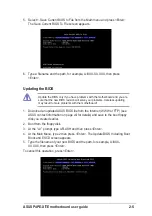
Страница 34: ...e ASUS contact information on page viii Save the file to a floppy disk 2 Reboot the computer 3 To use EZ Flash press Alt F2 during POST to display the following screen Write down the BIOS file name on a piece of paper You need to type the exact BIOS file name at the EZ Flash screen 4 Insert the disk that contains the new BIOS file into the floppy drive You will receive the error message WARNING De...

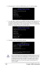
Страница 35: ...pe in the correct file name Press Enter 6 At the above prompt type Y to continue with the update process Pressing N exits the EZ Flash screen and reboots the system without updating the BIOS The following prompts appear if you typed Y 7 Press Y to update the main BIOS area BIOS Information in File BIOS Version P4PE X TE Boot Block WARNING Continue to update the BIOS Y N _ DO NOT shutdown or reset ...

Страница 36: ... copy AUTOEXEC BAT and CONFIG SYS to the disk 2 Type COPY D AFLASH AFLASH EXE A assuming D is your CD ROM drive to copy AFLASH EXE to the boot disk you created BIOS setup must specify Floppy as the first item in the boot sequence 4 In DOS mode type A AFLASH Enter to run AFLASH If the word unknown appears after Flash Memory the memory chip is either not programmable or is not supported by the ACPI ...

Страница 37: ...e boot floppy disk you created earlier 2 Boot from the floppy disk 3 At the A prompt type AFLASH and then press Enter 4 At the Main Menu type 2 then press Enter The Update BIOS Including Boot Block and ESCD screen appears 5 Type the filename of your new BIOS and the path for example A XXX XX XXX then press Enter To cancel this operation press Enter Update the BIOS only if you have problems with th...

Страница 38: ... When the programming is done the message Flashed Successfully appears 8 Follow the onscreen instructions to continue If you encounter problems while updating the new BIOS DO NOT turn off the system because this may cause boot problems Just repeat the process and if the problem persists load the original BIOS file you saved to the boot disk If the Flash Memory Writer utility is not able to success...

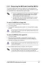
Страница 39: ... disk To recover the BIOS from a floppy disk 1 Insert the bootable floppy disk into the floppy disk drive 2 Turn on the computer 3 Follow the BIOS update procedure in section 2 1 2 Using AFLASH to update the BIOS DO NOT shutdown or reset the system while updating the BIOS Doing so may cause system boot failure The recovered BIOS may not be the latest BIOS version for this motherboard Visit the ASU...

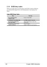
Страница 40: ...or detected One long beep followed by Video card not found or video card three short beeps memory bad High frequency beeps when CPU overheated system is working System running at a lower frequency 2 1 4 BIOS beep codes When you turn the power on and the system runs POST Power On Self Tests you will hear BIOS beeps Refer to the following table for the meaning of the beeps ...

Страница 41: ...es with its test routines If you wish to enter Setup after POST restart the system by pressing Ctrl Alt Delete or by pressing the reset button on the system chassis You can also restart by turning the system off and then back on Do this last option only if the first two failed The Setup program is designed to make it as easy to use as possible It is a menu driven program which means you can scroll...

Страница 42: ... highlighted field Home or PgUp Moves the cursor to the first field End or PgDn Moves the cursor to the last field F5 Resets the current screen to its Setup Defaults F10 Saves changes and exits Setup General help In addition to the Item Specific Help window the BIOS setup program also provides a General Help screen You may launch this screen from any menu by simply pressing F1 or the Alt H combina...

Страница 43: ...enus and sub menus If you accidentally make unwanted changes to any of the fields use the set default hot key F5 to load the Setup default values While moving around through the Setup program note that explanations appear in the Item Specific Help window located to the right of each menu This window displays the help text for the currently highlighted field System Time XX XX XX Sets the system to ...

Страница 44: ...e Main menu The passwords control access to the BIOS during system startup Passwords are not case sensitive meaning passwords typed in either uppercase or lowercase letters are accepted The BIOS Setup program allows you to specify two different passwords a Supervisor password and a User password If you did not set a Supervisor password anyone can access the BIOS Setup program If you did the Superv...

Страница 45: ...ready formatted on an older system Setup may detect incorrect parameters In these cases select User Type HDD to manually enter the IDE hard disk drive parameters Refer to the next section for details Before attempting to configure a hard disk drive make sure you have the correct configuration information supplied by the drive manufacturer Incorrect settings may cause the system to fail to recogniz...

Страница 46: ...ual Cylinders This field configures the number of cylinders Refer to the drive documentation to determine the correct value To make changes to this field set the Type field to User Type HDD and the Translation Method field to Manual Head This field configures the number of read write heads Refer to the drive documentation to determine the correct value To make changes to this field set the Type fi...

Страница 47: ...s 4 Sectors 8 Sectors 16 Sectors 32 Sectors Maximum SMART Monitoring Disabled This field allows you to enable or disable the S M A R T Self Monitoring Analysis and Reporting Technology system that utilizes internal hard disk drive monitoring technology This parameter is normally disabled because the resources used in the SMART monitoring feature may decrease system performance Configuration option...

Страница 48: ...t to Manual This field sets the frequency multiple between the CPU s internal frequency CPU speed and external frequency Set this field in conjunction with CPU Frequency MHz to match the speed of the CPU The item CPU Frequency Multiple is accessible only if you have an unlocked processor If your processor frequency multiple is locked you cannot change the setting of this item Selecting a frequency...

Страница 49: ... you to manually select the core voltage supplied to the CPU see next item However it is recommended that you keep the default setting Auto to allow the system to automatically determine the appropriate CPU core voltage CPU VCore 1 500V When the CPU VCore Setting parameter above is set to Manual the CPU VCore item allows you to select a specific CPU core voltage This field is not accessible when t...

Страница 50: ...the PS 2 mouse Otherwise IRQ12 can be used for expansion cards When you set this field to Enabled BIOS reserves IRQ12 whether or not a PS 2 mouse is detected at startup Configuration options Enabled Auto USB Legacy Support Auto This motherboard supports Universal Serial Bus USB devices The default of Auto allows the system to detect a USB device at startup If detected the USB controller legacy mod...

Страница 51: ...urable only when you set the SDRAM Configuration to User Defined SDRAM CAS Latency value depends on SDRAM SPD This item controls the latency between the SDRAM read command and the time the data actually becomes available Configuration options 2 5T 2T 1 5T SDRAM RAS to CAS Delay value depends on SDRAM SPD This item controls the latency between the DDR SDRAM active command and the read write command...

Страница 52: ...interface that transfers video data at 1066MB s AGP 4X is backward compatible so you may keep the default 4X Mode even if you are using an AGP 1X video card When set to 1X Mode the AGP interface only provides a peak data throughput of 266MB s even if you are using an AGP 4X card Configuration options 1X Mode 4X Mode Video Memory Cache Mode UC USWC uncacheable speculative write combining is a new c...

Страница 53: ...d drive strength reference voltage Configuration options Low Medium High Maximum Floppy Disk Access Control R W When set to Read Only this parameter protects files from being copied to floppy disks by allowing reads from but not writes to the floppy disk drive The default setting R W allows both reads and writes Configuration options R W Read Only Onboard Serial Port 1 3F8H IRQ4 Onboard Serial Por...

Страница 54: ...ions 1 3 Onboard AC97 Audio Controller Auto Auto allows the BIOS to detect whether you are using any audio device If an audio device is detected the onboard audio controller is enabled if no audio device is detected the controller is disabled Configuration options Disabled Auto Onboard Game Port 200H 207H This field sets the I O address for the game port Configuration options Disabled 200H 207H 20...

Страница 55: ...he number of USB 1 1 controllers that you wish to activate Configuration options Disabled 3 Controllers USB 2 0 Controller Enabled This field allows you to enable or disable the onboard USB 2 0 controller Set to Enabled if you wish to install USB 2 0 devices Configuration options Disabled Enabled Primary VGA BIOS PCI VGA Card This field allows you to select the primary graphics card Configuration ...

Страница 56: ...cates that you are using the ISA Configuration Utility ICU and that this particular IRQ is NOT required by a legacy ISA card Set the IRQ field to Yes if you install a legacy ISA card that requires a unique IRQ and you are NOT using ICU Configuration options No ICU Yes 2 5 Power Menu The Power menu allows you to reduce power consumption This feature turns off the video display and shuts down the ha...

Страница 57: ...ly installed as indicated by a battery and power cord icon labeled Power Management in the Control Panel Select the item Advanced in the Power Management Properties dialog box Video Off Option Suspend Off This field determines when to activate the video off feature for monitor power management Configuration options Always On Suspend Off Video Off Method DPMS OFF This field defines the video off fe...

Страница 58: ...PWR Loss Restart Disabled This allows you to set whether or not to reboot the system after power interruptions Disabled leaves your system off while Enabled reboots the system Previous State sets the system back to the state it was before the power interruption Configuration options Disabled Enabled Previous State Wake Power Up On Ext Modem Disabled This allows either settings of Enabled or Disabl...

Страница 59: ... an ATX power supply that provides at least 1A on the 5VSB lead Configuration options Disabled Space Bar Ctrl Esc Power Key Power On By PS 2 Mouse Disabled When set to Enabled this parameter allows you to use the PS 2 mouse to turn on the system This feature requires an ATX power supply that provides at least 1A on the 5VSB lead Configuration options Disabled Enabled Automatic Power Up Disabled Th...

Страница 60: ...plays the CPU and chassis fan speeds in rotations per minute RPM If any of the fans is not connected to the motherboard the specific field shows N A VCORE Voltage 3 3V Voltage 5V Voltage 12V Voltage The onboard hardware monitor automatically detects the voltage output through the onboard voltage regulators If any of the monitored items is out of range the following error message appears Hardware M...

Страница 61: ...ive This field allows you to select which IDE hard disk drive to use in the boot sequence Pressing Enter will show the product IDs of all connected IDE hard disk drives ATAPI CD ROM This field allows you to select which ATAPI CD ROM drive to use in the boot sequence Pressing Enter will show the product IDs of all your connected ATAPI CD ROM drives Other Boot Device Select INT18 Device Network Conf...

Страница 62: ...llow the operation to continue or use a virus free bootable floppy disk to restart and investigate your system Configuration options Disabled Enabled Quick Power On Self Test Enabled This field speeds up the Power On Self Test POST routine by skipping retesting a second third and fourth time Configuration options Disabled Enabled Boot Up Floppy Seek Enabled When enabled the BIOS will seek the flop...

Страница 63: ...er saves the changes while exiting Exit Discard Changes Select this option only if you do not want to save the changes that you made to the Setup program If you made changes to fields other than system date system time and password the BIOS asks for a confirmation before exiting Load Setup Defaults This option allows you to load the default values for each of the parameters on the Setup menus When...

Страница 64: ...2 32 Chapter 2 BIOS information ...

Страница 65: ...Chapter 3 This chapter describes the contents of the support CD that comes with the motherboard package Software support ...

Страница 66: ...t CD that came with the motherboard contains useful software and several utility drivers that enhance the motherboard features 3 2 1 Running the support CD To begin using the support CD simply insert the CD into your CD ROM drive The CD automatically displays the Drivers menu if Autorun is enabled in your computer The contents of the support CD are subject to change at any time without notice Visi...

Страница 67: ...the online help or readme file that came with the utility Intel Application Accelerator Driver This item installs the Intel Application Accelerator for Microsoft Windows 98SE ME NT4 0 2000 This program is designed to improve performance of the storage sub system and overall system performace Install the INF Driver before installing the Intel Application Accelerator SoundMAX Audio Driver and Applic...

Страница 68: ...ll ASUS Update This program allows you to download the latest version of the BIOS from the ASUS website Before using the ASUS Update make sure that you have an Internet connection so you can connect to the ASUS website PC CILLIN 2002 This item installs the PC cillin 2002 anti virus program View the PC cillin online help for detailed information Adobe Acrobat Reader This item installs the Adobe Acr...

Страница 69: ...ASUS P4PE X TE motherboard user guide 3 5 3 2 4 ASUS Contact Information Clicking the ASUS Contact Information tab displays as stated You may also find this information on page viii of this user guide ...

Страница 70: ...3 6 Chapter 3 Software support ...

Отзывы: