Asus P4C800-E Deluxe Скачать руководство пользователя страница 27

ASUS P4C800-E Deluxe motherboard user guide

2-1

2.1

Motherboard installation

Before you install the motherboard, study the configuration of your chassis
to ensure that the motherboard fits into it. The motherboard uses the ATX
form factor that measures 12 inches x 9.6 inches (30.5 x 24.5 cm).

Do not overtighten the screws! Doing so may damage the
motherboard.

2.1.1 Placement direction

When installing the motherboard, make sure that you place it into the
chassis in the correct orientation. The edge with external ports goes to the
rear part of the chassis as indicated in the image below.
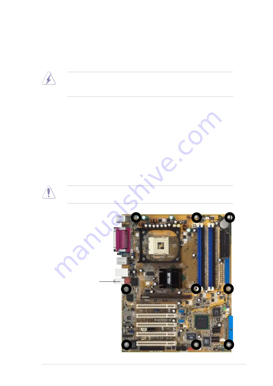
2.1.2 Screw holes

Place nine (9) screws into the holes indicated by circles to secure the
motherboard to the chassis.

Make sure to unplug the power cord before installing or removing the
motherboard. Failure to do so may cause you physical injury and
damage motherboard components.

Place this side towards
the rear of the chassis

Содержание P4C800-E Deluxe

Страница 1: ...Motherboard P4C800 E Deluxe User Guide ...

Страница 2: ...A PARTICULAR PURPOSE IN NO EVENT SHALL ASUS ITS DIRECTORS OFFICERS EMPLOYEES OR AGENTS BE LIABLE FOR ANY INDIRECT SPECIAL INCIDENTAL OR CONSEQUENTIAL DAMAGES INCLUDING DAMAGES FOR LOSS OF PROFITS LOSS OF BUSINESS LOSS OF USE OR DATA INTERRUPTION OF BUSINESS AND THE LIKE EVEN IF ASUS HAS BEEN ADVISED OF THE POSSIBILITY OF SUCH DAMAGES ARISING FROM ANY DEFECT OR ERROR IN THIS MANUAL OR PRODUCT SPECI...

Страница 3: ...rmation 2 1 Motherboard installation 2 1 2 1 1 Placement direction 2 1 2 1 2 Screw holes 2 1 2 2 Motherboard layout 2 2 2 3 Before you proceed 2 3 2 4 Central Processing Unit CPU 2 4 2 4 1 Overview 2 4 2 4 2 Installing the CPU 2 5 2 4 3 Installing the heatsink and fan 2 7 2 4 4 Connecting the CPU fan cable 2 9 2 5 System memory 2 10 2 5 1 Overview 2 10 2 5 2 Memory configurations 2 10 2 5 3 Instal...

Страница 4: ... menu screen 4 7 4 2 2 Menu bar 4 7 4 2 3 Navigation keys 4 7 4 2 4 Menu items 4 8 4 2 5 Sub menu items 4 8 4 2 6 Configuration fields 4 8 4 2 7 Pop up window 4 8 4 2 8 Scroll bar 4 8 4 2 9 General help 4 8 4 3 Main menu 4 9 4 3 1 System Time xx xx xxxx 4 9 4 3 2 System Date Day xx xx xxxx 4 9 4 3 3 Legacy Diskette A 1 44M 3 5 in 4 9 4 3 4 Language English 4 9 4 3 5 Primary and Secondary IDE Maste...

Страница 5: ...ot Settings Configuration 4 33 4 6 3 Security 4 35 4 7 Exit menu 4 38 Chapter 5 Software support 5 1 Install an operating system 5 1 5 2 Support CD information 5 1 5 2 1 Running the support CD 5 1 5 2 2 Drivers menu 5 2 5 2 3 Utilities menu 5 3 5 2 4 ASUS Contact Information 5 4 5 2 5 Other information 5 5 5 3 Software information 5 7 5 3 1 ASUS Update 5 7 5 3 2 ASUS MyLogo2 5 8 5 3 3 ASUS PC Prob...

Страница 6: ... harmful interference to radio or television reception which can be determined by turning the equipment off and on the user is encouraged to try to correct the interference by one or more of the following measures Reorient or relocate the receiving antenna Increase the separation between the equipment and receiver Connect the equipment to an outlet on a circuit different from that to which the rec...

Страница 7: ...your area If you are not sure about the voltage of the electrical outlet you are using contact your local power company If the power supply is broken do not try to fix it by yourself Contact a qualified service technician or your retailer Operation safety Before installing the motherboard and adding devices on it carefully read all the manuals that came with the package Before using the product ma...

Страница 8: ...r 2 Hardware information This chapter lists the hardware setup procedures that you have to perform when installing system components It includes description of the switches jumpers and connectors on the motherboard Chapter 3 Powering up This chapter describes the power up sequence and gives information on the BIOS beep codes Chapter 4 BIOS setup This chapter tells how to change system settings thr...

Страница 9: ...are products The ASUS websites are listed in the ASUS Contact Information on page x 2 Optional Documentation Your product package may include optional documentation such as warranty flyers that may have been added by your dealer These documents are not part of the standard package WARNING Information to prevent injury to yourself when trying to complete a task CAUTION Information to prevent damage...

Страница 10: ... 44370 Nobel Drive Fremont CA 94538 USA General Fax 1 502 933 8713 General Email tmd1 asus com Technical Support Support Fax 1 502 933 8713 General Support 1 502 995 0883 Notebook Support 1 510 739 3777 x5110 Web Site usa asus com Support Email tsd asus com ASUS COMPUTER GmbH Germany and Austria Address Harkortstr 25 40880 Ratingen BRD Germany General Email sales asuscom de for marketing requests ...

Страница 11: ...rts PC3200 2700 2100 unbuffered ECC or non ECC DDR DIMMs 1 x AGP Pro 8X 5 x PCI 1 x Wi Fi Supported by South Bridge ICH5R 2 x UltraDMA100 connectors 2 x Serial ATA connectors supports RAID0 configuration under Windows XP Supported by Promise PDC20378 controller optional 1 x UltraDMA 133 connector 2 x Serial ATA connectors RAID0 RAID1 RAID0 1 Multi RAID configurations VIA 6307 IEEE 1394 controller ...

Страница 12: ...onnectors for 4 additional USB ports CPU Power Chassis fan connectors 20 pin 4 pin ATX 12V power connectors IDE LED Power LED connectors Chassis intrusion connector 1 x IEEE 1394 connector on 1394 models only GAME MIDI connector S PDIF Out connector CD AUX Modem audio connectors Front panel audio connector Serial port 2 COM2 connector 4Mb Flash ROM AMI BIOS PnP DMI2 0 WfM2 0 SM BIOS2 3 Multi langu...

Страница 13: ...er 1 This chapter describes the features of the P4C800 E Deluxe motherboard It includes brief explanations of the special attributes of the motherboard and the new technology it supports Product introduction ...

Страница 14: ...ASUS P4C800 E Deluxe motherboard Chapter summary 1 1 Welcome 1 1 1 2 Package contents 1 1 1 3 Special features 1 2 1 4 Motherboard overview 1 6 ...

Страница 15: ...s your perfect vehicle to get ahead in the world of power computing Before you start installing the motherboard and hardware devices on it check the items in your package with the list below 1 2 Package contents Check your P4C800 E Deluxe package for the following items If any of the above items is damaged or missing contact your retailer ASUS P4C800 E Deluxe motherboard ASUS support CD InterVideo...

Страница 16: ...eliver up to 6 4GB s data transfer rate for the latest 3D graphics multimedia and Internet applications See page 2 10 Intel Performance Acceleration Technology PAT Incorporating the Intel PAT which is a turbo mode enabled in the Intel 875P to work with DDR 400 memory and boost system performance the motherboard delivers a new level of performance to beat Serial ATA technology The motherboard suppo...

Страница 17: ... variable Sample Rate Conversion SRC professional quality 103 dB out put with 94 dB SNR and analog enumeration capability The SoundMAX 4 XL software features the AudioESP Audio Enumeration and Sensing Process that allows intelligent detection of the peripherals plugged into the audio ports and identifies the incompatible devices if any AI Overclocking This feature allows convenient overclocking up...

Страница 18: ...idth asynchronous real time data interfacing between computers peripherals and consumer electronic devices such as camcorders VCRs printers TVs and digital cameras See page 2 31 USB 2 0 technology The motherboard implements the Universal Serial Bus USB 2 0 specification dramatically increasing the connection speed from the 12 Mbps bandwidth on USB 1 1 to a fast 480 Mbps on USB 2 0 USB 2 0 is backw...

Страница 19: ...bond ASIC A chassis intrusion event is retained in CMOS for more protection ASUS Update This utility allows you to update the motherboard BIOS through a user friendly interface Connect to the Internet then to the ASUS FTP site nearest you to obtain the latest BIOS version for your motherboard ASUS Multi language BIOS The multi language BIOS allows you to select the language of your choice from the...

Страница 20: ...nnector 4 DDR DIMM sockets 5 Floppy disk connector 6 IDE connectors 7 ATX power connector 8 AGP Pro 8X slot 9 Standby power LED 10 Flash ROM 11 Speech controller 12 RAID Ultra ATA133 connector 13 SATA connectors 14 SATA RAID connectors 15 RAID SATA IDE controller 16 South Bridge controller 17 IEEE 1394 controller optional 18 Wi Fi slot 19 Super I O controller 20 PCI slots 21 Audio CODEC 22 Gigabit...

Страница 21: ...ASUS P4C800 E Deluxe motherboard user guide 1 7 4 2 8 22 1 17 3 5 9 19 20 1615 12 7 6 11 21 10 14 18 13 23 34 27 28 29 30 24 26 32 33 25 31 ...

Страница 22: ...R DIMM sockets These four 184 pin DIMM sockets support up to 4GB system memory using unbuffered ECC or non ECC PC3200 PC2700 PC2100 DDR DIMMs Floppy disk connector This connector accommodates the provided ribbon cable for the floppy disk drive One side of the connector is slotted to prevent incorrect insertion of the floppy disk cable IDE connectors These dual channel bus master IDE connectors sup...

Страница 23: ...ler The fifth generation Intel I O Controller Hub ICH5R is a subsystem that integrates various I O functions including 2 channel ATA 100 bus master IDE controller SATA RAID controller up to eight USB 2 0 1 1 ports I O APIC LPC interface AC 97 2 3 interface and PCI 2 2 2 3 interface The ICH5 also contains the necessary arbitration and buffering for efficient utilization of these interfaces IEEE 139...

Страница 24: ...es IEEE 1394 port This port connects IEEE 1394 compliant devices like camcorders VCRs printers or digital cameras on 1394 models only RJ 45 port This port allows connection to a Local Area Network LAN through a network hub Line In jack This Line In light blue jack connects a tape player or other audio sources In 6 channel mode the function of this jack becomes Rear Speaker Out Line Out jack This L...

Страница 25: ... Hardware information This chapter describes the hardware setup procedures that you have to perform when installing system components It includes details on the switches jumpers and connectors on the motherboard ...

Страница 26: ...oard Chapter summary 2 1 Motherboard installation 2 1 2 2 Motherboard layouts 2 2 2 3 Before you proceed 2 3 2 4 Central Processing Unit CPU 2 4 2 5 System memory 2 10 2 6 Expansion slots 2 14 2 7 Jumpers 2 19 2 8 Connectors 2 21 ...

Страница 27: ...d 2 1 1 Placement direction When installing the motherboard make sure that you place it into the chassis in the correct orientation The edge with external ports goes to the rear part of the chassis as indicated in the image below 2 1 2 Screw holes Place nine 9 screws into the holes indicated by circles to secure the motherboard to the chassis Make sure to unplug the power cord before installing or...

Страница 28: ...X12V CHASSIS DDR DIMM_B1 64 72 bit 184 pin module PCI2 PCI3 PCI4 PCI5 IE1394_2 CLRTC FLOPPY PRI_IDE SEC_IDE PARALLEL PORT SPDIF_O SPDIF_OUT ATX Power Connector DDR DIMM_A1 64 72 bit 184 pin module DDR DIMM_A2 64 72 bit 184 pin module DDR DIMM_B2 64 72 bit 184 pin module PWR_FAN KBPWR CHA_FAN SB_PWR Intel ICH5R Intel 875P Memory Controller Hub MCH Intel 82547EI Gigabit LAN Speech Controller SATA1 S...

Страница 29: ...o avoid touching the ICs on them 4 Whenever you uninstall any component place it on a grounded antistatic pad or in the bag that came with the component 5 Before you install or remove any component ensure that the ATX power supply is switched off or the power cord is detached from the power supply Failure to do so may cause severe damage to the motherboard peripherals and or components When lit th...

Страница 30: ...rner This mark indicates the processor Pin 1 that should match a specific corner of the CPU socket Incorrect installation of the CPU into the socket may bend the pins and severely damage the CPU Gold Mark Notes on Intel Hyper Threading Technology 1 This motherboard supports Intel Pentium 4 CPUs with Hyper Threading Technology 2 Hyper Threading Technology is supported under Windows XP and Linux 2 4...

Страница 31: ...y Install the CPU 2 Power up the system and enter BIOS Setup see Chapter 4 Under the Advanced Menu make sure that the item Hyper Threading Technology is set to Enabled The item appears only if you installed a CPU that supports Hyper Threading Techonology 3 Reboot the computer 2 Unlock the socket by pressing the lever sideways then lift it up to a 90 100 angle Make sure that the socket lever is lif...

Страница 32: ...Carefully insert the CPU into the socket until it fits in place The CPU fits only in one correct orientation DO NOT force the CPU into the socket to prevent bending the pins and damaging the CPU 5 When the CPU is in place push down the socket lever to secure the CPU The lever clicks on the side tab to indicate that it is locked Gold Mark ...

Страница 33: ...hese steps to install the CPU heatsink and fan 1 Place the heatsink on top of the installed CPU making sure that the heatsink fits properly on the retention module base When you buy a boxed Intel Pentium 4 Processor the package includes the heatsink fan and retention mechanism In case you buy a CPU separately make sure that you use only Intel certified heatsink and fan Your boxed Intel Pentium 4 P...

Страница 34: ... the holes on each corner of the module base Keep the retention locks lifted upward while fitting the retention mechanism to the module base Make sure that the fan and retention mechanism assembly perfectly fits the heatsink and module base otherwise you cannot snap the hooks into the holes Retention Hole Retention Hook Snapped to the Retention Hole Retention Lock ...

Страница 35: ...cable to the connector on the motherboard labeled CPU_FAN 3 Push down the locks on the retention mechanism to secure the heatsink and fan to the module base When secure the retention locks should point to opposite directions Don t forget to connect the CPU fan connector Hardware monitoring errors may occur if you fail to plug this connector CPU Fan Connector CPU_FAN ...

Страница 36: ... recommended configurations may cause memory sizing error or system boot failure Use any of the recommended configurations in Table 1 2 In dual channel configurations install only identical the same type and size DDR DIMM pairs for each channel 3 Always install DIMMs with the same CAS latency For optimum compatibility it is recommended that you obtain memory modules from the same vendor 4 Make sur...

Страница 37: ...Mode DIMM_A1 DIMM_A2 DIMM_B1 DIMM_B2 blue black blue black Single channel 1 Populated 2 Populated 3 Populated 4 Populated Dual channel 1 Populated Populated 2 Populated Populated 3 Populated Populated Populated Populated Table 2 Memory frequency CPU FSB synchronization CPU FSB DDR DIMM Type Memory Frequency 800 MHz PC3200 PC2700 PC2100 400 333 266 MHz 533 MHz PC2700 PC2100 333 266 MHz 400 MHz PC21...

Страница 38: ...ECC 4 512MB Samsung M381L6423ETM CCC Samsung K4H560838E TCCC ECC 4 128MB Micron MT8VDDT1664AG 403B2 Micron MT46V16M8 5ESB 1 256MB Micron MT16VDDT3264AG 403B2 Micron MT46V16M8 5ESB 1 256MB Micron MT16VDDT3264AG 403B5 Micron MT46V16M8 5TESB 2 256MB Hynix HYMD232646B8J D43 AA Hynix HY5DU56822BT D43 4 512MB Hynix HYMD264646B8J D43 AA Hynix HY5DU56822BT D43 4 256MB TwinMos M2G9I08AFATT9F081AA4T TwinMos...

Страница 39: ...eak on the socket 2 5 4 Removing a DIMM Follow these steps to remove a DIMM 3 Firmly insert the DIMM into the socket until the retaining clips snap back in place and the DIMM is properly seated Locked Retaining Clip 1 Simultaneously press the retaining clips outward to unlock the DIMM 2 Remove the DIMM from the socket Unlocked Retaining Clip DDR DIMM notch A DDR DIMM is keyed with a notch so that ...

Страница 40: ...emove the bracket opposite the slot that you intend to use Keep the screw for later use 4 Align the card connector with the slot and press firmly until the card is completely seated on the slot 5 Secure the card to the chassis with the screw you removed earlier 6 Replace the system cover Make sure to unplug the power cord before adding or removing expansion cards Failure to do so may cause you phy...

Страница 41: ...10 Secondary IDE Channel These IRQs are usually available for ISA or PCI devices When using PCI cards on shared slots ensure that the drivers support Share IRQ or that the cards do not need IRQ assignments Otherwise conflicts will arise between the two PCI groups making the system unstable and the card inoperable IRQ assignments for this motherboard A B C D E F G H PCI slot 1 shared PCI slot 2 sha...

Страница 42: ... a LAN card SCSI card USB card and other cards that comply with PCI specifications 1 The PCI 5 slot and the Wi Fi slot may not be used at the same time 2 When installing long PCI cards it is recommended that you install them in PCI slots 1 2 or 5 Long PCI cards installed in PCI slots 3 and 4 may interfere with the SATA and GAME connectors ...

Страница 43: ...e with 0 8V or 1 5V specification Note the notches on the card golden fingers to ensure that they fit the AGP slot on your motherboard Install only 0 8V or 1 5V AGP cards This motherboard does not support 3 3V AGP cards If installing the ATi 9500 or 9700 Pro Series VGA cards use only the card version PN xxx xxxxx 30 or later for optimum performance and overclocking stability P4C800 E P4C800 E Acce...

Страница 44: ...read spectrum and infrared Devices that comply with the 802 11b standard operate at data rates of up to 11 Mbps for direct sequence spread spectrum The IEEE 802 11b specification allocates the 2 4 GHz frequency band into 14 overlapping operating channels Each Channel corresponds to a different set of frequencies If operating multiple 802 11b wireless PCI cards in the same vicinity the distance bet...

Страница 45: ...he CMOS memory of date time and system setup parameters by erasing the CMOS RTC RAM data The RAM data in CMOS that include system setup information such as system passwords is powered by the onboard button cell battery To erase the RTC RAM 1 Turn OFF the computer and unplug the power cord 2 Move the jumper cap from pins 1 2 default to pins 2 3 Keep the cap on pins 2 3 for about 5 10 seconds then m...

Страница 46: ... condition or in sleep mode 3 USB device wake up 3 pin USBPW12 USBPW34 USBPW56 USBPW78 Set these jumpers to 5V to wake up the computer from S1 sleep mode CPU stopped DRAM refreshed system running in low power mode using the connected USB devices Set to 5VSB to wake up from S3 and S4 sleep modes no power to CPU DRAM in slow refresh power supply in reduced power mode The USBPWR12 and USBPWR34 jumper...

Страница 47: ...ne end to the motherboard connect the other end to the floppy drive Pin 5 is removed to prevent incorrect insertion when using ribbon cables with pin 5 plug 4 SMB2 0 two 3 pin SMB20 These jumpers allow you to enable or disable the SMBus 2 0 feature supported on the motherboard By default pins 2 3 are shorted jumper caps on to disable the feature If you wish to install PCI devices that comply with ...

Страница 48: ...tation for the jumper settings BIOS supports specific device bootup You may configure two hard disks to be both master devices with two ribbon cables one for the primary IDE connector and another for the secondary IDE connector 1 Pin 20 on each IDE connector is removed to match the covered hole on the UltraDMA cable connector This prevents incorrect orientation when you connect the cables 2 The ho...

Страница 49: ...ng the RAID feature of the Intel ICH5R chipset See section 5 4 Intel RAID for Serial ATA for information on creating a RAID P4C800 E P4C800 E SATA Connectors SATA1 SATA2 GND RSATA_TXP1 RSATA_TXN1 GND RSATA_RXN1 RSATA_RXP1 GND GND RSATA_TXP2 RSATA_TXN2 GND RSATA_RXN2 RSATA_RXP2 GND Important notes on Serial ATA 1 In a legacy operating system DOS Windows 98 Windows Me Windows NT environment using th...

Страница 50: ...ing System Primary Secondary Port 0 Port 1 2 devices 2 devices 1 device 1 device 1 Windows 2000 XP 2 Windows 98 Me NT4 0 Configuration A Configuration B Configuration C Required IDE Configuration settings in BIOS Refer to the following table for the appropriate BIOS settings of the above P ATA and S ATA device configurations See section 4 3 6 IDE Configuration for details on the related BIOS items...

Страница 51: ...3 connector See Chapter 5 for details on RAID configuration 1 If you wish to create a RAID set make sure that you have connected the SATA cable and installed Serial ATA devices You cannot enter the SATARaid utility and SATA BIOS setup during POST if there are no connected Serial ATA devices 2 The Promise PDC20376 RAID controller does not support ATAPI devices such as CD ROMs DVD ROMs etc P4C800 E ...

Страница 52: ...5 for details on RAID configuration 1 If you wish to create a RAID set using UltraATA hard disks make sure that you have connected the UltraATA cable and installed UltraATA 133 hard disks 2 The Promise PDC20376 RAID controller does not support ATAPI devices such as CD ROMs DVD ROMs etc 6 SMBus connector 6 1 pin SMB This connector allows you to connect SMBus System Management Bus devices Devices co...

Страница 53: ...jumper caps on the fan connectors 7 Chassis intrusion connector 4 1 pin CHASSIS This lead is for a chassis designed with intrusion detection feature This requires an external detection mechanism such as a chassis intrusion sensor or microswitch When you remove any chassis component the sensor triggers and sends a high level signal to this lead to record a chassis intrusion event By default the pin...

Страница 54: ...Otherwise the system does not boot up 2 Make sure that your ATX 12V power supply can provide 8A on the 12V lead and at least 1A on the 5 volt standby lead 5VSB The minimum recommended wattage is 230W or 300W for a fully configured system The system may become unstable or may not boot up if the power is inadequate 10 Power supply thermal connector 2 pin TRPWR If your power supply has a thermal moni...

Страница 55: ...module 12 GAME MIDI connector 16 1 pin GAME This connector supports an optional GAME MIDI module Connect the GAME MIDI cable to this connector The GAME MIDI port on the module connects a joystick or a game pad for playing games and MIDI devices for playing or editing audio files The S PDIF module is purchased separately P4C800 E P4C800 E Digital Audio Connector 5V SPDIFOUT GND SPDIF_OUT P4C800 E P...

Страница 56: ...faster Internet connection interactive gaming and simultaneous running of high speed peripherals Connect an optional USB 2 0 GAME module to this header The module has two USB 2 0 ports that support the next generation USB peripherals such as high resolution cameras scanners and printers NEVER connect a 1394 cable to the either USB56 or USB78 connector Doing so will damage the motherboard P4C800 E ...

Страница 57: ...card 15 IEEE 1394 connector 10 1 pin IE1394_2 on 1394 models only This connector is for an optional 1394 module Attach the 10 1 pin 1394 cable plug from the module to this connector You may also connect a 1394 compliant internal hard disk to this connector NEVER connect a USB cable to the IEEE 1394 connector Doing so will damage the motherboard P4C800 E P4C800 E Internal Audio Connectors CD Black ...

Страница 58: ...ps only when you are connecting the front panel audio cable 17 Serial port 2 connector 10 1 pin COM2 This connector accommodates a second serial port using an optional serial port bracket Connect the bracket cable to this connector then install the bracket into a slot opening at the back of the system chassis The serial port bracket COM2 is purchased separately P4C800 E P4C800 E Front Panel Audio ...

Страница 59: ...creased to save power and to expand the life of certain system components Attach the case mounted suspend switch to this 2 pin connector ATX Power Switch Soft Off Switch Lead 2 pin PWRBTN This connector connects a switch that controls the system power Pressing the power switch turns the system between ON and SLEEP or ON and SOFT OFF depending on the BIOS or OS settings Pressing the power switch wh...

Страница 60: ...2 34 Chapter 2 Hardware information ...

Страница 61: ...Chapter 3 Powering up This chapter describes the power up sequence and gives information on the BIOS beep codes ...

Страница 62: ...ASUS P4C800 E Deluxe motherboard Chapter summary 3 1 Starting up for the first time 3 1 3 2 Vocal POST Messages 3 2 3 3 Powering off the computer 3 4 ...

Страница 63: ...plies with green standards or if it has a power standby feature the monitor LED may light up or switch between orange and green after the system LED turns on The system then runs the power on tests While the tests are running the BIOS beeps see BIOS beep codes table below or additional messages appear on the screen If you do not see anything within 30 seconds from the time you turned on the power ...

Страница 64: ...ST Message Action No CPU installed Install an Intel Pentium 4 Processor into the CPU socket System failed CPU test Check the CPU if properly installed Call ASUS technical support for assistance See the ASUS contact information on page x System failed memory test Install 184 pin unbuffered PC3200 2700 2100 DIMMs into the DIMM sockets Check if the DIMMs on the DIMM sockets are properly installed Mak...

Страница 65: ... have connected an IDE hard disk drive to the one of the IDE connectors on the motherboard See section 2 8 Connectors CPU temperature too high Check CPU fan if working properly CPU fan failed Check the CPU fan and make sure it turns on after you applied power to the system Make sure that your CPU fan supports the fan speed detection function CPU voltage out of range Check your power supply and mak...

Страница 66: ...er supply Using the dual function power switch While the system is ON pressing the power switch for less than 4 seconds puts the system to sleep mode or to soft off mode depending on the BIOS setting Pressing the power switch for more than 4 seconds lets the system enter the soft off mode regardless of the BIOS setting See section 4 5 Power Menu in Chapter 4 Using the OS shut down function If you ...

Страница 67: ...Chapter 4 BIOS setup This chapter tells how to change system settings through the BIOS Setup menus Detailed descriptions of the BIOS parameters are also provided ...

Страница 68: ...4C800 E Deluxe motherboard Chapter summary 4 1 Managing and updating your BIOS 4 1 4 2 BIOS Setup program 4 6 4 3 Main menu 4 9 4 4 Advanced menu 4 14 4 5 Power menu 4 27 4 6 Boot menu 4 32 4 7 Exit menu 4 38 ...

Страница 69: ...emove Programs icon from the Control Panel window c Click on the Startup Disk tab then on Create Disk button d Insert a 1 44 MB floppy disk when prompted Follow the suceeding screen instructions to complete the process 2 Copy the original or the latest motherboard BIOS to the bootable floppy disk 4 1 2 Using AFUDOS to update the BIOS Update the BIOS using the AFUDOS EXE utility in DOS environment ...

Страница 70: ...ing flash done Writing flash 0x0008CC00 9 When the BIOS update process is complete the utility returns to the DOS prompt A afudos iP4C800E rom AMI Firmware Update Utility Version 1 10 Copyright C 2002 American Megatrends Inc All rights reserved Reading file done Erasing flash done Writing flash 0x0008CC00 9 Verifying flash done A 5 Reboot the system from the hard disk DO NOT shutdown or reset the ...

Страница 71: ...the system 3 To launch EZ Flash press Alt F2 during POST to display the following 4 Insert the floppy disk that contains the BIOS file If the P4C800ED ROM file is found in the floppy disk EZ Flash performs the BIOS update process and automatically reboots the system when done DO NOT shutdown or reset the system while updating the BIOS Doing so may cause system boot failure User recovery requested ...

Страница 72: ...1 1 Creating a bootable floppy disk To recover the BIOS from a floppy disk 1 Boot the system 2 When a corrupted BIOS is detected the following message appears Bad BIOS checksum Starting BIOS recovery Checking for floppy 3 Insert a floppy disk that contains the original or the latest BIOS file for this motherboard P4C800ED ROM If the BIOS file that you downloaded from the ASUS website has a differe...

Страница 73: ...a corrupted BIOS is detected the following screen message appears Bad BIOS checksum Starting BIOS recovery Checking for floppy 3 Place the support CD in the CD ROM The support CD contains the original BIOS for this motherboard DO NOT shutdown or reset the system while updating the BIOS Doing so may cause system boot failure 4 When the BIOS update process is complete reboot the system Bad BIOS chec...

Страница 74: ...er the system provides you with the opportunity to run this program Press Delete during the Power On Self Test POST to enter the Setup utility Otherwise POST continues with its test routines If you wish to enter Setup after POST restart the system by pressing Ctrl Alt Delete or by pressing the reset button on the system chassis You can also restart by turning the system off and then back on Do thi...

Страница 75: ... item is highlighted 4 2 3 Navigation keys At the bottom right corner of a menu screen are the navigation keys for that particular menu Use the navigation keys to select items in the menu and change the settings System Time 11 10 19 System Date Thu 05 27 2003 Legacy Diskette A 1 44M 3 5 in Language English Primary IDE Master ST320413A Primary IDE Slave ASUS CD S340 Secondary IDE Master Not Detecte...

Страница 76: ... a menu screen when there are items that do not fit on the screen Press Up Down arrow keys or PageUp PageDown keys to display the other items on the screen 4 2 9 General help At the top right corner of the menu screen is a brief description of the selected item Scroll bar Select Screen Select Item Change Option F1 General Help F10 Save and Exit ESC Exit Advanced Chipset settings WARNING Setting wr...

Страница 77: ... Language English This field allows you to choose the BIOS language version from the available options Refer to section 4 2 1 BIOS menu screen for information on the menu screen items and how to navigate through them System Time 11 10 19 System Date Thu 05 27 2003 Legacy Diskette A 1 44M 3 5 in Language English Primary IDE Master ST320413A Primary IDE Slave ASUS CD S340 Secondary IDE Master Not De...

Страница 78: ...Mode Auto Enables or disables the LBA mode Setting to Auto enables the LBA mode if the device supports this mode and if the device was not previously formatted with LBA mode disabled Configuration options Disabled Auto Block Multi sector Transfer Auto Enables or disables data multi sectors transfers When set to Auto the data transfer from and to the device occurs multiple sectors at a time if the ...

Страница 79: ...Item Change Option F1 General Help F10 Save and Exit ESC Exit Onboard IDE Operate Mode Enhanced Mode Enhanced Mode Support On S ATA Configure S ATA as RAID No IDE Detect Time Out Sec 35 4 3 6 IDE Configuration The items in this menu allow you to set or change the configurations for the IDE devices installed in the system Select an item then press Enter if you wish to configure the item Onboard IDE...

Страница 80: ...ting system Set to Primary P ATA S ATA if you wish to use the primary Parallel ATA and Serial ATA ports or set to Secondary P ATA SATA to enable the secondary P ATA port instead Setting to P ATA Ports Only disables the two Serial ATA ports supported by ICH5 Configuration options Primary P ATA S ATA Secondary P ATA S ATA P ATA Ports Only The IDE Port Settings appears only when the item Onboard IDE ...

Страница 81: ...y Size 256MB 4 3 7 System Information This menu gives you an overview of the general system specifications The items in this menu are auto detected by BIOS AMI BIOS This item displays the auto detected BIOS information Processor This item displays the auto detected CPU specification System Memory This item displays the auto detected system memory IDE Detect Time Out 35 Selects the time out value f...

Страница 82: ...em Enter Go to Sub screen F1 General Help F10 Save and Exit ESC Exit 4 4 1 JumperFree Configuration Select Screen Select Item Change Option F1 General Help F10 Save and Exit ESC Exit AI Overclock Tuner Standard CPU Ratio 18 Performance Mode Auto Configure System Frequency Voltage AI Overclock Tuner Standard Allows selection of CPU overclocking options to achieve desired CPU internal frequency Sele...

Страница 83: ...ESC Exit AI Overclock Tuner Manual CPU External Frequency MHz 133 CPU Ratio 18 DRAM Frequency Auto AGP PCI Frequency MHz Auto CPU VCore Voltage Auto DDR Reference Voltage Auto AGP VDDQ Voltage 1 50V Performance Mode Auto Configure System Frequency Voltage When you set the AI Overclocking Tuner item to Manual the related overclocking items appear Setting to Turbo may cause the system to become unst...

Страница 84: ... the CPU VCore voltage A very high Vcore voltage may severely damage the CPU CPU VCore Voltage Auto Allows you to select a specific CPU VCore voltage Configuration options Auto 1 6000V 1 4750V AGP PCI Frequency MHz Auto Allows you to adjust to a higher AGP PCI frequency for better system performance and overclocking capability Configuration options Auto 66 66 33 33 72 73 36 36 80 00 40 00 Selectin...

Страница 85: ...hreading Technology Configuration options Disabled Enabled The item Hyper Threading Technology appears only if you installed an Intel Pentium 4 CPU that supports this feature Select Screen Select Item Change Option F1 General Help F10 Save and Exit ESC Exit Manufacturer Intel R Brand String Intel R Pentium R 4 CPU 2 53GHz Frequency 2400 MHz Ratio Status Locked Ratio Actual Value 18 Hyper Threading...

Страница 86: ...ptions Auto Enabled DRAM Idle Timer Auto Configuration options Infinite 0T 8T 16T 64T Auto DRAM Refresh Mode Auto Configuration options Auto 15 6 uSec 7 8 uSec 64 uSec 64T Select Screen Select Item Change Option F1 General Help F10 Save and Exit ESC Exit Advanced Chipset settings WARNING Setting wrong values in the sections below may cause system to malfunction Configure DRAM Timing by SPD Enabled...

Страница 87: ... Clocks 3 Clocks 2 Clocks DRAM Precharge Delay 8 Clocks Configuration options 8 Clocks 7 Clocks 6 Clocks 5 Clocks DRAM Burst Length 4 Clocks Configuration options 4 Clocks 8 Clocks Graphic Adapter Priority AGP PCI Allows selection of the graphics controller to use as primary boot device Configuration options AGP PCI PCI AGP Graphics Aperture Size 64MB Allows you to select the size of mapped memory...

Страница 88: ... no audio device is detected the controller is disabled Configuration options Disabled Auto OnBoard Promise Controller Enabled Allows you to enable or disable the onboard RAID controller Configuration options Disabled Enabled Operating Mode RAID Allows you to set the Promise RAID controller operating mode This item appears only when the item Onboard Promise Controller is set to Enabled Configurati...

Страница 89: ... Address is set to 3BC the Parallel Port Mode options are only Normal Bi directional and ECP Configuration options Normal Bi directional EPP ECP EPP Version 1 9 Allows selection of the Parallel Port EPP version This item appears only when the Parallel Port Mode is set to EPP Configuration options 1 9 1 7 ECP Mode DMA Channel DMA3 Allows selection of the Parallel Port ECP DMA channel This item appe...

Страница 90: ...S assigns an IRQ to PCI VGA card if the card requests for an IRQ When set to No BIOS does not assign an IRQ to the PCI VGA card even if requested Configuration options No Yes Take caution when changing the settings of the PCI PnP menu items Incorrect field values may cause the system to malfunction Select Screen Select Item Change Option F1 General Help F10 Save and Exit ESC Exit Plug and Play OS ...

Страница 91: ...ces Configuration options Available Reserved 4 4 6 USB Configuration The items in this menu allows you to change the USB related features Select an item then press Enter to display the configuration options Select Screen Select Item Change Option F1 General Help F10 Save and Exit ESC Exit Module Version 2 22 4 5 3 USB Devices Enabled None USB Function 8 USB Ports Legacy USB Support Auto USB 2 0 Co...

Страница 92: ...onfiguration options 10 Sec 20 Sec 30 Sec 40 Sec Emulation Type N A When set to Auto USB devices less than 530MB will be emulated as floppy drive and the remaining drives as hard drives Forced FDD option can be used to force an HDD formatted drive to boot as FDD for example ZIP drive The Device and Emulation Type items appear only when there are installed USB devices Legacy USB Support Auto Allows...

Страница 93: ...Report System Booting Disabled Speech Option Disable Enable Speech Speech POST Reporter Enabled Allows you to enable or disable the ASUS Speech POST Reporter feature Configuration options Disabled Enabled The following items appear only when Speech POST Reporter is set to Enabled Report IDE Error Disabled Configuration options Disabled Enabled Report System Booting Disabled Configuration options D...

Страница 94: ...able the Instant Music feature in BIOS Configuration options Disabled Enabled When Instant Music is enabled the PS 2 keyboard power up feature is automatically disabled Instant Music CD ROM Drive IDE Secondary Master Allows you to select the CD ROM drive that you wish to use for the Instant Music CD playback Configuration options IDE Primary Master IDE Primary Slave IDE Secondary Master IDE Second...

Страница 95: ...select the ACPI state to be used for system suspend Configuration options S1 POS Only S3 Only Auto 4 5 2 Repost Video on S3 Resume No Determines whether to invoke VGA BIOS POST on S3 STR resume Configuration options No Yes 4 5 3 ACPI 2 0 Support No Allows you to add more tables for ACPI 2 0 specifications Configuration options No Yes 4 5 4 ACPI APIC Support Enabled Allows you to enable or disable ...

Страница 96: ...he Advanced Power Management APM feature Configuration options Disbaled Enabled Video Power Down Mode Suspend Allows you to select the video power down mode Configuration options Disabled Standby Suspend Hard Disk Power Down Mode Suspend Allows you to select the hard disk power down mode Configuration options Disabled Standby Suspend Suspend Time Out Disabled Allows you to select the specified tim...

Страница 97: ...ower On By External Modem Disabled This allows either settings of Enabled or Disabled for powering up the computer when the external modem receives a call while the computer is in Soft off mode Configuration options Disabled Enabled The computer cannot receive or transmit data until the computer and applications are fully running Thus connection cannot be made on the first try Turning an external ...

Страница 98: ... monitor automatically detects and displays the motherboard CPU and power supply temperatures Select Disabled if you do not wish to display the detected temperatures Q Fan Control Disabled This item allows you to enable or disable the ASUS Q Fan feature that smartly adjusts the fan speeds for more efficient system operation When this field is set to Enabled the Fan Speed Ratio item appears to allo...

Страница 99: ...lled additional devices and the system requires more ventilation Configuration options 11 16 12 16 13 16 14 16 15 16 The above item appears only when the Q Fan Control item is set to Enabled CPU Fan Speed xxxxRPM or N A Chassis Fan Speed xxxxRPM or N A Power Fan Speed xxxxRPM or N A The onboard hardware monitor automatically detects and displays the CPU chassis and power fan speeds in rotations pe...

Страница 100: ...creen Select Item Change Option F1 General Help F10 Save and Exit ESC Exit 1st Boot Device First Floppy Drive 2nd Boot Device PM ST320413A 3rd Boot Device PS ASUS CD S340 Boot Device Priority Specifies the boot sequence from the available devices A device enclosed in parenthesis has been disabled in the corresponding type menu 1st xxth Boot Device 1st Floppy Drive These items specify the boot devi...

Страница 101: ...bled Enabling this item allows BIOS to skip some power on self tests POST while booting to decrease the time needed to boot the system When set to Disabled BIOS performs all the POST items Configuration options Disabled Enabled Full Screen Logo Enabled Setting to Disabled displays the normal POST messages Setting to Enabled displays the OEM logo instead of the POST messages Configuration options D...

Страница 102: ... Error Enabled When set to Enabled the system waits for F1 key to be pressed when error occurs Configuration options Disabled Enabled Hit DEL Message Display Enabled When set to Enabled the system displays the message Press DEL to run Setup during POST Configuration options Disabled Enabled Interrupt 19 Capture Disabled When set to Enabled this function allows the option ROMs to trap Interrupt 19 ...

Страница 103: ...sword The Supervisor Password item on top of the screen shows the default Not Installed After you have set a password this item shows Installed To set a Supervisor Password 1 Select the Change Supervisor Password item and press Enter 2 On the password box that appears type a password composed of letters and or numbers then press Enter Your password should have at least six characters 3 Confirm the...

Страница 104: ...Supervisor Password Installed User Password Not Installed Change Supervisor Password User Access Level Full Access Change User Password Clear User Password Password Check Setup Boot Sector Virus Protection Disabled Select Screen Select Item Change Option F1 General Help F10 Save and Exit ESC Exit Security Settings Enter to change password Enter again to disable password After you have set a superv...

Страница 105: ...irm the password when prompted The message Password Installed appears after you have successfully set your password The User Password item now shows Installed To change the user password follow the same steps as in setting a user password Clear User Password Select this item if you wish to clear the user password Password Check Setup When set to Setup BIOS checks for user password when accessing t...

Страница 106: ...ved to the CMOS RAM The CMOS RAM is sustained by an onboard backup battery and stays on even when the PC is turned off When you select this option a confirmation window appears Select Yes to save changes and exit Pressing Esc does not immediately exit this menu Select one of the options from this menu or F10 from the legend bar to exit If you attempt to exit the Setup program without saving your c...

Страница 107: ...n appears Select Yes to discard any changes and load the previously saved values Load Setup Defaults This option allows you to load the default values for each of the parameters on the Setup menus When you select this option or if you press F5 a confirmation window appears Select Yes to load default values Select Exit Saving Changes or make other changes before saving the values to the non volatil...

Страница 108: ...4 40 Chapter 4 BIOS Setup ...

Страница 109: ...Chapter 5 Software support This chapter describes the contents of the support CD that comes with the motherboard package ...

Страница 110: ...C800 E Deluxe motherboard Chapter summary 5 1 Install an operating system 5 1 5 2 Support CD information 5 1 5 3 Software information 5 7 5 4 Promise RAID configurations 5 25 5 5 Intel RAID for Serial ATA 5 33 ...

Страница 111: ... support CD that came with the motherboard contains useful software and several utility drivers that enhance the motherboard features 5 2 1 Running the support CD To begin using the support CD simply insert the CD into your CD ROM drive The CD automatically displays the Drivers menu if Autorun is enabled in your computer The contents of the support CD are subject to change at any time without noti...

Страница 112: ...ll this utility in three modes interactive silent and unattended preload The interactive mode requires user input during installation This is not required in the silent and unattended preload modes Refer to the online help or readme file that came with the utility Intel Application Accelerator Driver This item installs the Intel Application Accelerator driver If you are using Windows XP this drive...

Страница 113: ...Update make sure that you have an Internet connection so you can connect to the ASUS website ASUS PC Probe This smart utility monitors the fan speed CPU temperature and system voltages and alerts you on any detected problems This utility helps you keep your computer at a healthy operating condition Install ASUS Update This program allows you to download the latest version of the BIOS from the ASUS...

Страница 114: ...ortable Document Format PDF Promise Array Management Utility This item installs the RAID utility for monitoring or performing maintenance to a FastTrak Mirrored RAID 1 or Striped Mirrored RAID 0 1 disk array Winbond Voice Editor This program is for recording and customizing wave files for the ASUS POST Reporter Use this program if you wish to change the default vocal POST messages See section 3 2 ...

Страница 115: ...of the screen give additional information on the motherboard and the contents of the support CD Click an icon to display the specified information Motherboard Info The window displays the general specifications of the motherboard Browse this CD The window displays the support CD contents in graphical format ...

Страница 116: ...l Support Form The window displays the ASUS Technical Support Request Form that you have to fill up when requesting technical support Filelist The window displays the contents of the support CD and a brief description of each in text format ...

Страница 117: ...ASUS Update The ASUS Update is a utility that allows you to update the motherboard BIOS This utility requires an Internet connection either through a network or an Internet Service Provider ISP Follow these steps to use the ASUS Update 2 Select your desired update method then click Next 1 Launch the utility from your Windows Start menu Programs AsusUpdate Vx xx xx AsusUpdate The ASUS Update initia...

Страница 118: ...atically installed when you install the ASUS Update utility from the support CD See section 5 2 3 Utilities menu 1 Launch the ASUS Update utility See section 5 3 1 ASUS Update 2 When prompted for the BIOS update method select the option Update BIOS from a file 3 Specify the location of the BIOS file such as from a floppy disk Click Next Before using ASUS MyLogo2 feature use the AFUDOS utility to m...

Страница 119: ...ew boot logo Instead of starting from ASUS Update you may also launch ASUS MyLogo2 directly from the Windows Start menu to change your BIOS boot logo After you have modified the BIOS file with the new logo use the ASUS Update utility to upload the new BIOS 5 When you click on an image it displays larger on the MyLogo2 screen If you wish you may create your own boot logo image in GIF JPG or BMP fil...

Страница 120: ...ernal frequencies through the DMI Explorer Starting ASUS PC Probe When ASUS PC Probe starts a splash screen appears allowing you to select whether to show the screen again when you open PC Probe or not To bypass this startup screen clear the Show up in next execution check box The PC Probe icon appears on the taskbar system tray indicating that ASUS PC Probe is running Clicking the icon allows you...

Страница 121: ... temperature for supported processors only Temperature Warning threshold adjustment Move the slider up to increase the threshold level or down to decrease the threshold level Fan Monitor Shows the PC fan rotation Voltage Monitor Shows the PC voltages Fan Warning threshold adjustment Move the slider up to increase the threshold level or down to decrease the threshold level ...

Страница 122: ...ws the used and free space of the PC s hard disk drives and the file allocation table or file system used Fan Control Lets you enable disable Smart Fan Control Smart Fan Control adjusts the fan speed automatically based on the current CPU temperature and predefined threshold CPU Cooling System Setup Lets you select when to enable software CPU cooling When When CPU Overheated is selected the CPU co...

Страница 123: ...nformation pertinent to the PC such as CPU type CPU speed and internal external frequencies and memory size Utility Lets you run programs outside of the ASUS Probe modules To run a program click Execute Program NOTE This feature is currently unavailable Information Memory Shows the PC memory load memory usage and paging file usage ...

Страница 124: ...king the PC Probe icon brings up a menu to open or exit ASUS PC Probe and pause or resume all system monitoring When the ASUS PC Probe senses a problem with your PC portions of the ASUS PC Probe icon change to red the PC speaker beeps and the ASUS PC Probe monitor appears ...

Страница 125: ...ing the program Launch the program either from the Winbond Voice Editor icon on your desktop or from the Windows Start menu Programs Winbond Voice Editor Voice Editor The Winbond Voice Editor screen appears Playing the default wave files To play the default wave files simply click on a POST event on the left side of the screen then click the Play button The default language setting is English To a...

Страница 126: ...pen The event messages for the language you selected appear on the Voice Editor screen For some languages not all events have a corresponding message due to file size constraints 3 Click on the Write button to update the EEPROM 4 Click Yes on the confirmation window that appears The next time you boot your computer the POST messages are announced in the language that you selected ...

Страница 127: ... list of POST events on the leftmost column of the screen 2 Prepare your message for each event The total compressed size for all the wave files must not exceed 1Mbit so make your messages as short as possible 3 Use a recording software such as Windows Recorder to record your messages 4 Save the messages as wave files WAV It is recommended that you save your files in low quality to keep them small...

Страница 128: ... the Edit button The Event Sound Editor window appears 8 Locate and select your wave file for the event then click on the arrow opposite Voice1 The file you selected appears on the space next to it 9 Click OK to return to the Voice Editor screen 10 Do steps 7 to 9 for the other events 11 When done click the Save button A window appears prompting you to save your configuration 12 Type a file name w...

Страница 129: ...stallation wizard to install the AD1985 Audio Driver and Application from the support CD that came with the motherboard package to activate the 6 channel audio feature You must use 4 channel or 6 channel speakers for this setup SoundMAX 4 XL requires Microsoft Windows 98SE ME 2000 XP Make sure that one of these operating systems is installed before installing SoundMAX If the SoundMAX4 XL software ...

Страница 130: ...y launch the setup wizards by clicking the Configuration button when AudioESP detects and verifies a newly connected peripheral or by clicking on the icon from the SoundMAX control panel Speaker wizard Follow the screen instructions to configure the speakers to your desired settings Microphone wizard Follow the screen instructions to configure the microphone to your desired settings ...

Страница 131: ...ferences page of the SoundMAX4 XL allows you to change various audio settings Listening environment options The SoundMAX4 XL support several audio technologies including SoundMAX SPX Animated Audio 3DPA MultiDrive 5 1 EnvironmentFC MacroFX ZoomFX and Virtual Theater Surround ...

Страница 132: ...rk if you installed and enabled an add on sound card 3 Instant Music only supports PS 2 keyboard To enable ASUS Instant Music 1 Connect the analog audio cable from the optical drive CD ROM DVD ROM or CD RW drive to the 4 pin CD In connector labeled CD on the motherboard See section 2 8 Connectors for the location Make sure to connect the CD ROM audio cable Otherwise you cannot control the audio vo...

Страница 133: ...t Music Configuration 4 The Instant Music CD ROM Drive item appears if you enabled Instant Music Highlight the item then press Enter to display the CD ROM options 5 Save your changes and exit BIOS Setup To use ASUS Instant Music 1 Ensure that the power cord is plugged to a grounded power source so that the system has a standby power 2 Use either one of the two sets of special function keys on your...

Страница 134: ...phone to the headphone jack on the CD ROM drive front panel 4 Place an audio CD on the drive 5 Press Esc to turn ON Instant Music 6 Press F1 or the Space Bar to play the first track on the CD If there is no CD on the drive and you press F1 or Space Bar the drive tray ejects 7 Refer to the Instant Music function key definitions on the previous page to select other tracks or control the volume 8 Pre...

Страница 135: ...g copies and maintains an identical image of data from one drive to a second drive If one drive fails the disk array management software directs all applications to the surviving drive as it contains a complete copy of the data in the other drive This RAID configuration provides data protection and increases fault tolerance to the entire system RAID 0 1 is data striping and data mirroring combined...

Страница 136: ... Connect the power cable to the power connector on each drive 5 Boot the system and enter the BIOS Setup Utility 6 Go to the Advanced menu in BIOS and set the appropriate IDE configuration settings 7 Save your changes and Exit Setup 8 Proceed to section 5 4 2 for the next procedure 5 4 1 Install the hard disks The PDC20378 chipset supports Ultra ATA 133 100 66 hard disk drives For optimal performa...

Страница 137: ...lowing 2 Press Ctrl F simultaneously to display the FastBuild utility main menu FastBuild tm Utility 2 00 c 2002 2005 Promise Technology Inc Auto Setup 1 1 View Drive Assignments 2 2 Define Array 3 3 Delete Array 4 4 Rebuild Array 5 5 Press 1 5 to select Option ESC Exit Main Menu Keys Available MBFastTrak378 tm BIOS version 1 00 c 2000 2005 Promise Technology Inc All Rights Reserved No Array defin...

Страница 138: ... are installing you may need to install the RAID driver during or after the OS installation 5 Once the array is created use the FDISK utility to format the array as a single hard drive 6 After you have formatted the arrayed drives install an operating system OS The OS will treat the RAID 0 array as a single drive unit 7 Install the RAID driver from the support CD that came with the motherboard pac...

Страница 139: ...n Array has been created Press any key to reboot Do you want the disk image to be duplicated to another Yes No Y Create and Duplicate N Create Only 2 Use the arrow keys to go to the field Optimize Array for and select Security with the space bar The Mode field displays Mirror 3 Press Ctrl Y to save your selection 4 The following message appears FastBuild tm Utility 2 00 c 2002 2005 Promise Technol...

Страница 140: ... the Create and Duplicate option The next window prompts you to select the source drive to use 6 Use the arrow keys to select the source drive The FastBuild utility will copy all the data from the source drive to the target drive 7 Press Ctrl Y to save the selection and start the duplication The following message appears Do you want the disk image to be duplicated to another Yes No Y Create and Du...

Страница 141: ...ew Array 3 This command allows you to view the drive assignments of hard disks in an array Delete Array 4 This command deletes an array to reconfigure the system Deleting an array does not remove information on the hard disks If an array is deleted by mistake recover it immediately by redefining it as the deleted array Rebuild Array 5 This command restores the array and system data after faults on...

Страница 142: ... Enter FastBuild tm Utility 2 00 c 2002 2005 Promise Technology Inc Keys Available Up Down ESC Exit Enter Select Up Down ESC Exit Enter Select Rebuild Array Menu Array No RAID Mode Total Drv Capacity Status Array 1 Mirror Stripe 4 7999 Critical Array 2 Array 3 Array 4 8 Confirm the command to copy data from the intact source hard disk onto a new replacement hard disk A progress gauge displays the ...

Страница 143: ...pressing Delete during the Power On Self Test POST See section 4 2 BIOS Setup program for more information on entering the Setup utility 2 From the Main menu select IDE Configuration to display the sub menu items 3 Set the IDE Configuration items as follows 4 Press F10 to save your changes and exit the Setup utility Onboard IDE Operate Mode Enhanced Mode Enhanced Mode Support On S ATA Configure S ...

Страница 144: ...A RAID Configuration Utility Copyright C 2003 Intel Corporation All Rights Reserved v3 x x xxxx MAIN MENU 1 Create RAID Volume 2 Delete RAID Volume 3 Reset Disks to Non RAID 4 Exit Select Select ESC Exit ESC Exit Enter Select Menu Enter Select Menu 5 5 2 Installing Serial ATA hard disks 1 A Serial ATA hard disk requires SATA data 4 conductor and power cables Make sure that you have the appropriate...

Страница 145: ...e Change TAB Next TAB Next ESC Previous Menu ESC Previous Menu Enter Select Enter Select 2 Type a name for your RAID volume using 1 to 16 characters letters and or numbers no special characters Press Enter 3 Use the Up and Down arrow keys to select the stripe size for the RAID 0 array Press Enter to make the selection The available values range from 8 KB to 128 KB The default is 64 KB Select a str...

Страница 146: ...e TAB Next TAB Next ESC Previous Menu ESC Previous Menu DEL Delete Volume DEL Delete Volume Name Level Drives Capacity Status Bootable RAID_Volume1 RAID0 Stripe 2 37 2GB Normal Yes To delete a RAID volume 1 Select the option 2 Delete RAID Volume and press Enter to delete the RAID volume 2 When a confirmation message appears press Y to permanently delete the RAID volume Are you sure you want to del...

Страница 147: ...v3 x x xxxx MAIN MENU 1 Create RAID Volume 2 Delete RAID Volume 3 Reset Disks to Non RaID 4 Exit Select Select ESC Exit ESC Exit Enter Select Menu Enter Select Menu Resetting all RAID data will remove any internal RAID structures from all RAID disks including disks with working volumes These structures are used to maintain the RAID volumes By removing these structures the drive will revert back to...

Страница 148: ...5 38 Chapter 5 Software support ...

Страница 149: ...oard 3 6 9 Refer to the Quick Setup Guide when installing components or devices for the items indicated in this reference card Requires an ATX power supply PLED Ground PWR 5V Speaker Speaker Connector Power LED Ground Reset SW SMI Lead ExtSMI Ground Reset Ground Ground ATX Power Switch PLED IDE_LED IDE_LED IDE_LED ...

Отзывы: