background image

3-8

Chapter 3: Motherboard info

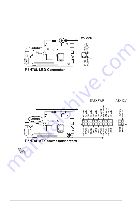
5.  LED connector (6-1 pin LED_CON)

This connector supports the Power and HDD activity LEDs in the system front 

panel.

6.  ATX power connectors (24-pin EATXPWR, 4-pin ATX12V)

These connectors are for ATX power supply plugs. The plugs from the power 

supply are designed to fit these connectors in only one orientation. Find the 

proper orientation and push down firmly until the connectors completely fit.

• 

DO NOT

 forget to connect the 4-pin ATX +12 V power plug; otherwise, the 

system will not boot.

•  We recommend that you use a PSU with a higher power output when 

configuring a system with more power-consuming devices. The system 

may become unstable or may not boot up if the power is inadequate.  

•  Ensure that your power supply unit (PSU) can provide at least the minimum 

power required by your system. 

Содержание P2-P5N9300

Страница 1: ...P2 P5N9300 P4 P5N9300 ASUS PC Desktop Barebone User Manual ...

Страница 2: ...TICULAR PURPOSE IN NO EVENT SHALL ASUS ITS DIRECTORS OFFICERS EMPLOYEES OR AGENTS BE LIABLE FOR ANY INDIRECT SPECIAL INCIDENTAL OR CONSEQUENTIAL DAMAGES INCLUDING DAMAGES FOR LOSS OF PROFITS LOSS OF BUSINESS LOSS OF USE OR DATA INTERRUPTION OF BUSINESS AND THE LIKE EVEN IF ASUS HAS BEEN ADVISED OF THE POSSIBILITY OF SUCH DAMAGES ARISING FROM ANY DEFECT OR ERROR IN THIS MANUAL OR PRODUCT SPECIFICAT...

Страница 3: ...CD information 2 3 2 3 1 Running the Support CD 2 3 2 3 2 Drivers menu 2 4 2 3 3 Utilities menu 2 5 2 3 4 Make Disk menu 2 6 2 3 5 Manual menu 2 7 2 3 6 ASUS Contact information 2 7 2 3 7 Other information 2 8 2 4 ASUS AI Manager 2 10 2 4 1 Installing AI Manager 2 10 2 4 2 Launching AI Manager 2 10 2 4 3 AI Manager Quick Bar 2 10 2 4 4 Main 2 11 2 4 5 My favorites 2 14 2 4 6 Support 2 15 2 4 7 Inf...

Страница 4: ...ms 4 14 4 2 5 Submenu items 4 14 4 2 6 Configuration fields 4 14 4 2 7 Pop up window 4 15 4 2 8 General help 4 15 4 3 Main menu 4 16 4 3 1 System Time 4 16 4 3 2 System Date 4 16 4 3 3 SATA1 2 4 17 4 3 4 ESATA 4 18 4 3 5 HDD SMART Monitoring 4 18 4 4 Advanced menu 4 19 4 4 1 JumperFree Configuration 4 19 4 4 2 CPU Configuration 4 23 4 4 3 Chipset 4 24 4 4 4 PCIPnP 4 25 4 4 5 Onboard Device Configu...

Страница 5: ...f contents 4 6 Boot menu 4 33 4 6 1 Boot Device Priority 4 33 4 6 2 Boot Settings Configuration 4 34 4 6 3 Security 4 35 4 7 Tools menu 4 37 4 7 1 ASUS EZ Flash 2 4 37 4 7 2 Express Gate 4 38 4 8 Exit menu 4 39 ...

Страница 6: ...vice may not cause harmful interference and This device must accept any interference received including interference that may cause undesired operation This equipment has been tested and found to comply with the limits for a Class B digital device pursuant to Part 15 of the FCC Rules These limits are designed to provide reasonable protection against harmful interference in a residential installati...

Страница 7: ...es are not damaged If you detect any damage contact your dealer immediately To avoid short circuits keep paper clips screws and staples away from connectors slots sockets and circuitry Avoid dust humidity and temperature extremes Do not place the product in any area where it may become wet Place the product on a flat and stable surface Do not block the air vents on the chassis Always provide prope...

Страница 8: ...D 3 Chapter 3 Motherboard information This chapter gives information about the motherboard that comes with the system This chapter includes the motherboard layout jumper settings and connector locations 4 Chapter 4 BIOS information This chapter tells how to change system settings through the BIOS Setup menus and describes the BIOS parameters Lithium Ion Battery Warning CAUTION Danger of explosion ...

Страница 9: ...h as warranty flyers that may have been added by your dealer These documents are not part of the standard package Conventions used in this guide To ensure that you perform certain tasks properly take note of the following symbols used throughout this manual WARNING Information to prevent injury to yourself when trying to complete a task CAUTION Information to prevent damage to the components when ...

Страница 10: ...P4 P5N9300 barebone system with ASUS motherboard 3 in 1 storage card reader PCIE raiser card 200W power supply unit 2 Cables Power cable Serial ATA power cable and signal cable 3 CD Support CD 4 Quick Installation Guide Optional items 1 ASUS VGA card 2 Infrared card for P4 P5N9300 only 3 Remote control for P4 P5N9300 only Optional items are not included in the system package They are purchased sep...

Страница 11: ...5N9300 Chapter 1 System introduction This chapter gives a general description of ASUS P2 P5N9300 P4 P5N9300 The chapter lists the system features including introduction on the front and rear panels and internal components ...

Страница 12: ... the Intel Prescott Smithfield Cedarmill Kentsfield Conroe Wolfdale and Yorkfield processors The system supports up to 4GB system memory using unbuffered non ECC DDR2 800 667MHz DIMMs high resolution graphics via integrated graphics controller Serial ATA USB 2 0 and eight channel high definition audio CODEC 1 2 Front panel The illustrations below show the front panels of the P2 P5N9300 and P4 P5N9...

Страница 13: ...RO card 7 USB 2 0 port 9 This Universal Serial Bus 2 0 USB 2 0 port connects to USB 2 0 devices such as a mouse printer scanner camera PDA and others 8 USB eSATA port This port connects to a USB 2 0 device or an external Serial ATA hard disk drive 9 4 pin IEEE 1394 port This port connects to an IEEE 1394 device such as a digital camrecorder 10 USB 2 0 ports 10 and 11 These Universal Serial Bus 2 0...

Страница 14: ... 1 Power connector 2 Voltage selector This switch allows you to adjust the system input voltage according to the voltage supply in your area If the voltage supply in your area is 100 127V set this switch to 115V If the voltage supply in your area is 200 240V set this switch to 230V 1 3 Rear panel The illustration below shows the rear panel of the P2 P5N9300 and P4 P5N9300 Rear panel 1 2 4 5 6 3 10...

Страница 15: ...bwoofer Center Subwoofer Black Rear Speaker Out Rear Speaker Ou Rear Speaker Out Gray Side Speaker Out 9 PS 2 mouse port green This port connects to a PS 2 mouse 10 PS 2 keyboard port purple This port connects to a PS 2 keyboard 11 LAN RJ 45 port This port allows Gigabit connection to a Local Area Network LAN through a network hub Refer to the audio configuration table below for the function of th...

Страница 16: ... the motherboard PCIE slot 5 ASUS motherboard 6 DIMM slots 7 LGA775 socket 1 2 3 4 5 6 7 13 Optical S PDIF_OUT port This port connects to an external audio output device via an optical S PDIF cable 14 VGA port This port connects to a VGA monitor or other VGA compatible devices 15 HDMI port This port is for a High Definition Multimedia Interface HDMI connector and is HDCP compliant allowing playbac...

Страница 17: ...ASUS P2 P5N9300 P4 P5N9300 Chapter 2 Starting up This chapter helps you power up the system and install drivers and utilities from the Support CD ...

Страница 18: ...ates to maximize the features of your hardware 2 2 Powering up your system Press the power button to power up the system To ensure that the OS work properly install the drivers included in the Support CD Motherboard settings and hardware options vary Use the setup procedures presented in this chapter for reference only Refer to your OS documentation for detailed information P2 P5N9300 P4 P5N9300 ...

Страница 19: ...ASSETUP EXE file from the BIN folder Double click the ASSETUP EXE file to run the CD Click an item to install Click an icon to display Support CD motherboard information 2 3 Support CD information The support CD that comes with the system package contains the drivers software applications and utilities that you can install to get all the system features The contents of the Support CD are subject t...

Страница 20: ...IA chipset driver program Realtek Audio Driver Installs the Realtek audio driver NVIDIA HDMI Audio Driver Installs the NVIDIA HDMI audio driver Realtek RTL8111B C LAN Driver Installs the Realtek RTL8111B C LAN driver VIA Card Reader Driver Installs the VIA card reader driver 2 3 2 Drivers menu The Drivers menu shows the available device drivers if the system detects installed devices Install the n...

Страница 21: ...vice Provider ISP ASUS Screen Saver Installs theASUS screensaver ASUS AI Manager Installs the ASUS AI Manager where you can launch AI disk AI Security and AI Probe easily Acrobat Reader 8 Installs the Adobe Acrobat Reader that allows you to open view and print documents in Portable Document Format PDF ASUS Express Gate Installer Installs theASUS Express Gate FarStone Utility Installs the FarStone ...

Страница 22: ...eate an NVIDIA Serial ATA SATA RAID driver disk for 32bit 64bit Windows Vista operating systems NVIDIA 32bit 64bit XP AHCI Driver Allows you to create an NVIDIA AHCI driver disk for 32bit 64bit Windows XP operating systems NVIDIA 32bit 64bit Vista AHCI Driver Allows you to create an NVIDIA AHCI driver disk for 32bit 64bit Windows Vista operating systems 2 3 4 Make Disk menu The Make Disk menu allo...

Страница 23: ...he Contact tab to display the ASUS contact information 2 3 5 Manual menu The Manual menu contains a list of supplementary user manuals The manuals are in Portable Document Format PDF format Install the Adobe Acrobat Reader from the Utilities menu before opening a manual ...

Страница 24: ...of the screen give additional information on the motherboard and the contents of the Support CD Click an icon to display the specified information Browse this CD Displays the Support CD contents in graphical format Motherboard Info Displays the general specifications of the motherboard ...

Страница 25: ...Technical Support Form Displays the ASUS Technical Support Request Form that you have to fill out when requesting technical support Filelist Displays the contents of the Support CD and a brief description of each item in text format ...

Страница 26: ...CD 2 Click the Utilities tab then click ASUS AI Manager 3 Follow the onscreen instructions to complete the installation 2 4 2 Launching AI Manager You can launch AI Manager right after installation or anytime from the Windows desktop To launch AI Manager from the Windows desktop click Start All Programs ASUS AI Manager AI Manager v1 xx xx The AI Manager Quick Bar appears After launching the applic...

Страница 27: ... files list Select the item that you want to clear then click Apply Click to switch between a full screen AI Manager window and the Quick bar Click to keep AI Manager in the taskbar Click to close AI Manager 2 4 4 Main Launch AI Disk AI Security or AI Probe from the Main menu Click the small triangle to open or close the Main menu Click to open close the Main menu ...

Страница 28: ...USB flash disk and CD DVD disk which ensures more security for your data To lock a device 1 If you are using AI Security for the first time key in a password consisting of up to 20 alphanumeric characters 2 Confirm your password 3 Key in your password hint optional 4 Click OK 5 Select the device you want to lock then click Apply ...

Страница 29: ...ock a device 1 Deselect the device you locked then click Apply 2 Key in your password then click OK To change your password click Change Password and follow the onscreen instructions AI Probe AI Probe automatically detects the motherboard and CPU temperatures CPU fan speed and CPU voltage It also allows you to adjust these values manually ...

Страница 30: ...Add and then select from the succeeding screen the application you want to add to the My Favorites menu 2 Click Open The application you selected is added and its icon appears Right click an icon in the My Favorites menu to open delete or rename the corresponding application Double click an icon to open the corresponding application ...

Страница 31: ...lays the general information of your system motherboard CPU BIOS memory and other devices installed 2 4 6 Support The Support menu displays links to the ASUS international website online technical support website online download support website and contact information website ...

Страница 32: ...2 16 Chapter 2 Starting up ...

Страница 33: ...P5N9300 P4 P5N9300 Chapter 3 Motherboard info This chapter gives information about the motherboard that comes with the system This chapter includes the motherboard layout jumper settings and connector locations ...

Страница 34: ...nfo 3 1 Introduction The P2 P5N9300 P4 P5N9300 barebone system comes with an ASUS motherboard This chapter provides technical information about the motherboard for future upgrades or system reconfiguration 3 2 Motherboard layout ...

Страница 35: ...omputer and unplug the power cord 2 Move the jumper cap from pins 1 2 default to pins 2 3 Keep the cap on pins 2 3 for about 5 10 seconds then move the cap back to pins 1 2 3 Plug the power cord and turn ON the computer 6 Hold down the Del key during the boot process to enter the BIOS setup program then reenter data Except when clearing the RTC RAM never remove the cap on CLRTC jumper default posi...

Страница 36: ...cted USB devices Set these jumpers to 5VSB to wake up from S3 and S4 sleep modes no power to CPU DRAM in slow refresh power supply in reduced power mode The USB device wake up feature requires a power supply that can provide 500mA on the 5VSB lead for each USB port Otherwise the system would not power up The total current consumed must NOT exceed the power supply capability 5VSB whether under norm...

Страница 37: ...ng a 3 pin CPU fan 3 Keyboard power 3 pin KBPWR This jumper allows you to enable or disable the keyboard wake up feature Set this jumper to pins 2 3 5VSB to wake up the computer by pressing a key on the keyboard the default is the Space Bar This feature requires an ATX power supply that can supply at least 1A on the 5VSB lead and a corresponding setting in the BIOS ...

Страница 38: ... Windows XP Service Pack 1 before using Serial ATA hard disk drives When using the connectors in IDE mode connect the primary boot hard disk drive to the SATA1 or SATA2 connector 2 COM port connector 10 1pin COM1 This connector is for a serial COM port Connect the serial port module cable to this connector then install the module to a slot opening at the back of the system chassis ...

Страница 39: ... ground pin of the connector DO NOT forget to connect the CPU fan cable to the CPU fan connector Insufficient air flow inside the system may damage the motherboard components It is not a jumper DO NOT place a jumper cap on the CPU fan connector We recommend that you connect a high definition front panel audio module to this connector to get the motherboard s high definition audio capability 4 Back...

Страница 40: ...nnectors in only one orientation Find the proper orientation and push down firmly until the connectors completely fit DO NOT forget to connect the 4 pin ATX 12 V power plug otherwise the system will not boot We recommend that you use a PSU with a higher power output when configuring a system with more power consuming devices The system may become unstable or may not boot up if the power is inadequ...

Страница 41: ...back of the system chassis 8 USB connectors 10 1 pin USB56 USB78 These connectors are for USB 2 0 ports Connect the USB module cable to any of these connectors then install the module to a slot opening at the back of the system chassis These USB connectors comply with USB 2 0 specification that supports up to 480 Mbps connection speed Never connect a 1394 cable to the USB connectors Doing so will ...

Страница 42: ...sor or switch cable to this connector The chassis intrusion sensor or switch sends a high level signal to this connector when a chassis component is removed or replaced The signal is then generated as a chassis intrusion event By default the pin labeled Chassis Signal and Ground are shorted with a jumper cap Remove the jumper caps only when you intend to use the chassis intrusion detection feature...

Страница 43: ...ASUS P2 P5N9300 P4 P5N9300 Chapter 4 This chapter tells how to change the system settings through the BIOS Setup menus Detailed descriptions of the BIOS parameters are also provided BIOS setup ...

Страница 44: ... BIOS file to a bootable floppy disk or USB flash disk in case you need to restore the BIOS in the future Copy the original motherboard BIOS file using the ASUS Update or AwardBIOS Flash utilities All the floppy devices mentioned in this chapter are USB floppy devices The BIOS screens in this chapter are for reference only The actual BIOS screen displays may not be the same as shown 4 1 1 Creating...

Страница 45: ...ile that you can use as backup when the BIOS fails or gets corrupted during the updating process Updating the BIOS To update the BIOS using the AwardBIOS flash utility 1 Download the latest BIOS file for this motherboard from the ASUS website at www asus com Rename the file to P5N78L BIN and save it to a bootable floppy disk USB flash disk or CD ROM in FAT 16 12 format Save only the updated BIOS f...

Страница 46: ...Please input File Name For MCP7A P5N78L 00 DATE 10 16 2008 Flash Type MXIC M25L4005 8Mb SPI File Name to Program P5N78L BIN 7 Press N when the utility prompts you to save the current BIOS file The following screen appears 8 The utility verifies the BIOS file in the floppy disk USB flash disk or CD ROM and starts flashing the BIOS file DO NOT turn off or reset the system during the flashing process...

Страница 47: ...OM is not write protected and has enough free space to save the file 3 Key in a filename for the current BIOS file in the Save current BIOS as field then press Enter 1 Follow steps 1 to 6 in Updating the BIOS 2 Press Y when the utility prompts you to save the current BIOS file The following screen appears AwardBIOS Flash Utility for ASUS V1 32 C Phoenix Technologies Ltd All Rights Reserved Message...

Страница 48: ... floppy disk to P5N78L ROM Recovering the BIOS from a floppy disk To recover the BIOS from a floppy disk 1 Turn on the system 2 Insert the floppy disk with the original or updated BIOS file into the floppy disk drive The utility displays the following message and automatically checks the floppy disk for the original or updated BIOS file Bad BIOS checksum Starting BIOS recovery Checking for floppy ...

Страница 49: ...ptical drive for the original or updated BIOS file The utility then updates the corrupted BIOS file Bad BIOS checksum Starting BIOS recovery Checking for floppy 3 Restart the system after the utility completes the updating process The recovered BIOS may not be the latest BIOS version for this motherboard Visit the ASUS website at www asus com to download the latest BIOS file When the original or u...

Страница 50: ...t Press Alt F2 during POST to display the following ASUSTek EZ Flash 2 BIOS ROM Utility B334 Current ROM Update ROM C Note Enter Select S Save Esc Exit Tab Switch Up Down Home End Move FLASH TYPE MXIC MX25L8005 8Mb SPI PATH C BOARD P5N78L VER 0306 DATE 10 16 2008 BOARD Unknown VER Unknown DATE Unknown Insert the floppy disk USB flash disk that contains the BIOS file to the floppy disk drive or a U...

Страница 51: ...the motherboard BIOS in Windows environment The ASUS Update utility allows you to Save the current BIOS file Download the latest BIOS file from the Internet Update the BIOS from an updated BIOS file Update the BIOS directly from the Internet and View the BIOS version information This utility is available in the Support CD that comes with the motherboard package ASUS Update requires an Internet con...

Страница 52: ... Next Updating the BIOS through the Internet To update the BIOS through the Internet 1 Launch the ASUS Update utility from the Windows desktop by clicking Start Programs ASUS ASUSUpdate ASUSUpdate The ASUS Update main window appears 2 Select Update BIOS from the Internet option from the dropdown menu then click Next ...

Страница 53: ...OS from a file option from the dropdown menu then click Next 4 From the FTP site select the BIOS version that you want to download Click Next 5 Follow the onscreen instructions to complete the update process The ASUS Update utility is capable of updating itself through the Internet Always update the utility to get all its features 3 Locate the BIOS file from the Open window then click Open 4 Follo...

Страница 54: ... can enable the security password feature or change the power management settings This requires you to reconfigure your system using the BIOS Setup program so that the computer can recognize these changes and record them in the CMOS RAM of the SPI chip The firmware chip on the motherboard stores the Setup utility When you start up the computer the system provides you with the opportunity to run th...

Страница 55: ...key on the keyboard until the desired item is highlighted The BIOS setup screens shown in this chapter are for reference only They may not exactly match what you see on your screen Visit the ASUS website at www asus com to download the latest BIOS file Legend bar General help Menu bar Submenu items Configuration fields Menu items Select Menu Item Specific Help Change the internal time Phoenix Awar...

Страница 56: ...nu item to the left or right Up or Down arrow Moves the highlight up or down between fields Page Down or minus Scrolls backward through the values for the highlighted field Page Up or plus Scrolls forward through the values for the highlighted field Enter Brings up a selection menu for the highlighted field F10 Saves changes and exit 4 2 5 Submenu items A solid triangle before each item on each me...

Страница 57: ...Select Menu Item Specific Help Hard Disk A M A R T capability support Phoenix AwardBIOS CMOS Setup Utility Main Advanced Power Boot Tools Exit F1 Help Select Item Change Value F5 Setup Defaults ESC Exit Select Menu Enter Select SubMenu F10 Save and Exit System Time 15 30 36 System Date Thu Oct 30 2008 SATA 1 None SATA 2 None ESATA 3 None HDD SMART Monitoring Disabled Installed Memory 1024MB Usable...

Страница 58: ... to set the system time Select Menu Item Specific Help Hard Disk A M A R T capability support Phoenix AwardBIOS CMOS Setup Utility Main Advanced Power Boot Tools Exit F1 Help Select Item Change Value F5 Setup Defaults ESC Exit Select Menu Enter Select SubMenu F10 Save and Exit System Time 15 30 36 System Date Thu Oct 30 2008 SATA 1 None SATA 2 None ESATA 3 None HDD SMART Monitoring Disabled Instal...

Страница 59: ...A Mode Auto Selects the UDMA mode Configuration options Disabled Auto SATA 1 Auto Allows you to enable or disable SATA 1 Configuration options None Auto Manual Access Mode Auto Sets the sector addressing mode Configuration options CHS LBA Large Auto Before configuring a hard disk drive ensure that you have the correct configuration information supplied by the drive manufacturer Incorrect settings ...

Страница 60: ...y detects the values opposite the dimmed items Capacity Cylinder Head Sector and Transfer Mode These values are not user configurable These items show 0 if no eSATA device is installed in the system ESATA Auto Allows you to enable or disable ESATA Configuration options None Auto Manual Access Mode Auto Sets the sector addressing mode Configuration options CHS LBA Large Auto Before configuring a ha...

Страница 61: ...cific Help System clock mode Auto Set FSB and memory speed automatically Linked Enter FSB speed manually Memory speed changes proportionally Phoenix AwardBIOS CMOS Setup Utility Advanced F1 Help Select Item Change Value F5 Setup Defaults ESC Exit Select Menu Enter Select SubMenu F10 Save and Exit JumperFree Configuration FSB Memory Clock Mode Auto x FSB Memory Ratio Auto x FSB QDR MHz Auto Actual ...

Страница 62: ...e item to Linked The FSB QDR MHz item is also configurable when you set the FSB Memory Clock Mode item to Unlinked Actual FSB QDR MHz This item reflects the actual frequency after the system reboots The following item becomes user configurable when you set FSB Memory Clock Mode to Unlinked MEM DDR MHz 799 Allows you to adjust memory frequency Use the and keys to adjust the frequency You can also t...

Страница 63: ...to x tREF Auto Memory Timing Setting Optimal Allows you to load the optimal timings or enter timings manually Configuration options Optimal Expert tCL CAS Latency Auto Configuration options Auto 1 2 3 4 5 6 7 tRCD Auto Configuration options Auto 1 2 3 4 5 6 7 tRP Auto Configuration options Auto 1 2 3 4 5 6 7 tRAS Auto Configuration options Auto 1 2 3 4 5 6 7 31 Command Per Clock CMD Auto Configura...

Страница 64: ...DR2 voltage Configuration options Auto 1 75V 1 80V 1 85V 1 90V 1 95V 2 00V 2 05V 2 10V MEM Power Features Disabled Allows you to enable or disable the MEM power features Configuration options Disabled Enabled Advance Path Auto Allows you to enable or disable the advance path Configuration options Auto Enable Disable Refer to the CPU documentation before setting the CPU voltage Setting a high volta...

Страница 65: ...led CPU Internal Thermal Control Auto Configuration options Auto Disabled Limit CPUID MaxVal Disabled Setting this item to Enabled allows legacy operating systems to boot even without support for CPUs with extended CPUID functions Configuration options Disabled Enabled Enhanced C1 CIE Disabled Allows you to enable or disable C1E Support Configuration options Enabled Disabled Execute Disable Bit En...

Страница 66: ...lect Menu Enter Select SubMenu F10 Save and Exit Chipset Spread Spectrum Control Primary Display Adapter PCI E Hybrid SLI Disabled x Display Detection Disable Onboard GPU Auto Frame Buffer Size 64M Retrain PCIE dev to Gen2 Auto Spread Spectrum Control Select Menu Item Specific Help Phoenix AwardBIOS CMOS Setup Utility Advanced F1 Help Select Item Change Value F5 Setup Defaults ESC Exit Select Menu...

Страница 67: ...nfiguration options Auto Always Enable Frame Buffer Size 64M Allows you to select the frame buffer size Configuration options 32M 64M 128M 256M 512M Disabled Retrain PCIE dev to Gen2 Auto Configuration options Auto Disabled 4 4 4 PCIPnP Plug Play O S No When set to No the BIOS configures all the devices in the system When set to Yes and if you install a Plug and Play operating system the operating...

Страница 68: ...nabled Onboard LAN Enabled Onboard LAN Boot ROM Disabled Serial Port1 Address 3F8 IRQ4 CIR Port Address 310 CIR Port IRQ 11 Select Menu Item Specific Help Phoenix AwardBIOS CMOS Setup Utility Advanced IDE Function Setup SATA Controller 1 2 Enabled IDE Prefetch Mode Enabled IDE Function Setup SATA Controller 1 2 Enabled Allows you to enable or disable the onboard SATA controllers Configuration opti...

Страница 69: ...nable or disable the onboard LAN boot ROM Configuration options Enabled Disabled Serial Port1 Address 3F8 IRQ4 Allows you to select the Serial Port1 base address Configuration options Disabled 3F8 IRQ4 2F8 IRQ3 3E8 IRQ4 2E8 IRQ3 Auto CIR Port Address 310 Allows you to select the CIR port address Configuration options Disabled 310 320 CIR Port IRQ 11 Allows you to select the CIR port IRQ Configurat...

Страница 70: ...sabled Enabled USB 2 0 Controller Enabled Allows you to enable or disable the USB 2 0 controller Configuration options Disabled Enabled 4 4 6 USB Configuration Select Menu Item Specific Help Enable or Disable USB 1 1 and 2 0 Controller Phoenix AwardBIOS CMOS Setup Utility Advanced F1 Help Select Item Change Value F5 Setup Defaults ESC Exit Select Menu Enter Select SubMenu F10 Save and Exit USB Con...

Страница 71: ...elect Menu Item Specific Help Select the ACPI state used for System Suspend Phoenix AwardBIOS CMOS Setup Utility Main Advanced Power Boot Tools Exit F1 Help Select Item Change Value F5 Setup Defaults ESC Exit Select Menu Enter Select SubMenu F10 Save and Exit ACPI Suspend Type S1 S3 ACPI APIC support Enabled APM Configuration Hardware Monitor 4 5 2 ACPI APIC Support Enabled Allows you to enable or...

Страница 72: ...ws you to set the event after the power button is pressed for more than 4 seconds Configuration options Suspend Instant Off Power On By PCIE Devices Disabled When setting this item to Enabled you can wake the system through a PCI Express card This feature requires an ATX power supply that provides at least 1A on the 5VSB lead Configuration options Disabled Enabled 4 5 3 APM Configuration Select Me...

Страница 73: ...menu for the hour field 2 Key in an hour value Min 0 Max 23 then press Enter 3 Press Tab to move to the minutes field then press Enter 4 Key in a minute value Min 0 Max 59 then press Enter 5 Press Tab to move to the seconds field then press Enter 6 Key in a second value Min 0 Max 59 then press Enter HPET Support Enabled Configuration options Disabled Enabled WDRT Support Enabled Configuration opti...

Страница 74: ...2V 5V Voltage 5 10V 12V Voltage 12 09V CPU Temperature 47ºC M B Temperature 32ºC CPU Fan Speed 2177 RPM CPU Fan Speed Warning 600 RPM Q Fan Controller Enabled Allows you to enable or disable the Q Fan controller Configuration options Disabled Enabled Vcore Voltage 3 3V Voltage 5V Voltage 12V Voltage xxxV or Ignored The onboard hardware monitor automatically detects the voltage output through the o...

Страница 75: ...ice priority sequence from the available devices The number of device items that appears on the screen depends on the number of devices installed in the system Configuration options Removable Hard Disk CDROM Disabled Select Menu Item Specific Help Select Boot Device Priority Phoenix AwardBIOS CMOS Setup Utility Main Advanced Power Boot Tools Exit F1 Help Select Item Change Value F5 Setup Defaults ...

Страница 76: ...nabled Select Menu Item Specific Help Press Enter to enable or disable Phoenix AwardBIOS CMOS Setup Utility Main Extreme Tweaker Boot Tools Exit F1 Help Select Item Change Value F5 Setup Defaults ESC Exit Select Menu Enter Select SubMenu F10 Save and Exit Boot Settings Configuration Case Open Warning Enabled Quick Boot Enabled Bootup Num Lock On Typematic Rate Setting Disabled x Typematic Rate Cha...

Страница 77: ...word 1 Select an item then press Enter 2 From the password box key in a password which consists of up to eight alphanumeric characters then press Enter 3 Confirm your password when prompted then press Enter The password field shows Set Select Menu Item Specific Help Supervisor password controls full access Enter to change password Phoenix AwardBIOS CMOS Setup Utility Main Extreme Tweaker Boot Tool...

Страница 78: ...ing unauthorized use Forgot your password If you forget your password you can clear it by erasing the CMOS Real Time Clock RTC RAM The RAM data containing the password information is powered by the onboard button cell battery If you need to erase the CMOS RAM refer to section 3 3 Jumper for instructions Password Check Selects whether the password is required every time the system boots or only whe...

Страница 79: ...up Defaults ESC Exit Select Menu Enter Select SubMenu F10 Save and Exit ASUS EZ Flash 2 Express Gate 4 7 1 ASUS EZ Flash 2 Allows you to run ASUS EZ Flash 2 When you press Enter a confirmation message appears Use the left right arrow key to select between Yes or No then press Enter to confirm your choice ASUSTek EZ Flash 2 BIOS ROM Utility B334 Current ROM Update ROM C Note Enter Select S Save Esc...

Страница 80: ...ons No Reset When setting this item to Reset ensure to save the setting to the BIOS so that the user data will be cleared the next time you enter the Express Gate User data includes the Express Gate s settings as well as any personal information stored by the web browser bookmarks cookies browsing history etc This is useful in the rare case where corrupt settings prevent the Express Gate environme...

Страница 81: ... a confirmation before exiting Load Setup Default This option allows you to load the default values for each of the parameters on the Setup menus When you select this option or if you press F5 a confirmation window appears Select YES to load the default values Select Exit Save Changes or make other changes before saving the values to the non volatile RAM Discard Changes This option allows you to d...

Страница 82: ... ASUSTek COMPUTER INC Address City No 150 LI TE RD PEITOU TAIPEI 112 TAIWAN R O C Country TAIWAN Authorised representative in Europe ASUS COMPUTER GmbH Address City HARKORT STR 21 23 40880 RATINGEN Country GERMANY ...

Отзывы: